EP0863384A1 - Circuit et procédé d'opération d'un capteur de position utilisant les éléments à effet Hall - Google Patents
Circuit et procédé d'opération d'un capteur de position utilisant les éléments à effet Hall Download PDFInfo
- Publication number
- EP0863384A1 EP0863384A1 EP98103698A EP98103698A EP0863384A1 EP 0863384 A1 EP0863384 A1 EP 0863384A1 EP 98103698 A EP98103698 A EP 98103698A EP 98103698 A EP98103698 A EP 98103698A EP 0863384 A1 EP0863384 A1 EP 0863384A1
- Authority
- EP
- European Patent Office
- Prior art keywords
- hall element
- activated
- hall
- hall elements
- control unit
- Prior art date
- Legal status (The legal status is an assumption and is not a legal conclusion. Google has not performed a legal analysis and makes no representation as to the accuracy of the status listed.)
- Granted
Links
Images


Classifications
-
- G—PHYSICS
- G01—MEASURING; TESTING
- G01D—MEASURING NOT SPECIALLY ADAPTED FOR A SPECIFIC VARIABLE; ARRANGEMENTS FOR MEASURING TWO OR MORE VARIABLES NOT COVERED IN A SINGLE OTHER SUBCLASS; TARIFF METERING APPARATUS; MEASURING OR TESTING NOT OTHERWISE PROVIDED FOR
- G01D5/00—Mechanical means for transferring the output of a sensing member; Means for converting the output of a sensing member to another variable where the form or nature of the sensing member does not constrain the means for converting; Transducers not specially adapted for a specific variable
- G01D5/12—Mechanical means for transferring the output of a sensing member; Means for converting the output of a sensing member to another variable where the form or nature of the sensing member does not constrain the means for converting; Transducers not specially adapted for a specific variable using electric or magnetic means
- G01D5/14—Mechanical means for transferring the output of a sensing member; Means for converting the output of a sensing member to another variable where the form or nature of the sensing member does not constrain the means for converting; Transducers not specially adapted for a specific variable using electric or magnetic means influencing the magnitude of a current or voltage
- G01D5/142—Mechanical means for transferring the output of a sensing member; Means for converting the output of a sensing member to another variable where the form or nature of the sensing member does not constrain the means for converting; Transducers not specially adapted for a specific variable using electric or magnetic means influencing the magnitude of a current or voltage using Hall-effect devices
- G01D5/145—Mechanical means for transferring the output of a sensing member; Means for converting the output of a sensing member to another variable where the form or nature of the sensing member does not constrain the means for converting; Transducers not specially adapted for a specific variable using electric or magnetic means influencing the magnitude of a current or voltage using Hall-effect devices influenced by the relative movement between the Hall device and magnetic fields
-
- G—PHYSICS
- G01—MEASURING; TESTING
- G01D—MEASURING NOT SPECIALLY ADAPTED FOR A SPECIFIC VARIABLE; ARRANGEMENTS FOR MEASURING TWO OR MORE VARIABLES NOT COVERED IN A SINGLE OTHER SUBCLASS; TARIFF METERING APPARATUS; MEASURING OR TESTING NOT OTHERWISE PROVIDED FOR
- G01D5/00—Mechanical means for transferring the output of a sensing member; Means for converting the output of a sensing member to another variable where the form or nature of the sensing member does not constrain the means for converting; Transducers not specially adapted for a specific variable
- G01D5/12—Mechanical means for transferring the output of a sensing member; Means for converting the output of a sensing member to another variable where the form or nature of the sensing member does not constrain the means for converting; Transducers not specially adapted for a specific variable using electric or magnetic means
- G01D5/244—Mechanical means for transferring the output of a sensing member; Means for converting the output of a sensing member to another variable where the form or nature of the sensing member does not constrain the means for converting; Transducers not specially adapted for a specific variable using electric or magnetic means influencing characteristics of pulses or pulse trains; generating pulses or pulse trains
- G01D5/249—Mechanical means for transferring the output of a sensing member; Means for converting the output of a sensing member to another variable where the form or nature of the sensing member does not constrain the means for converting; Transducers not specially adapted for a specific variable using electric or magnetic means influencing characteristics of pulses or pulse trains; generating pulses or pulse trains using pulse code
- G01D5/2497—Absolute encoders
Definitions
- the invention relates to a method for operating a position transmitter, preferably a rotary encoder that has Hall elements, according to the preamble of claim 1 and a position sensor according to the preamble of claim 10 for performing the method.
- Encoders have long been known from the prior art have a magnetic division with a code structure. According to the DE 44 42 371 A1 of the applicant are characterized by such divisions multi-track alternating magnetization of a rotationally symmetric Body, which is proportional to that supplied to the encoder Rotary motion rotates. This alternating magnetization is with a Rotational movement detected by static Hall elements for each track of the division and output as an absolute position signal.
- a multi-turn transmitter is known from EP 0 331 828 A1, which in principle composed of two measuring systems. It is incremental optical measuring system the exact position in the range of a 360 ° rotation the optical division and also the number of revolutions the optical division with the help of a magnetic detector. From this, a control unit can also determine the absolute position several revolutions of the encoder. Becomes the multiturn encoder the stored number is connected to the supply voltage Revolutions and the stored incremental value. To the Reducing electrical power consumption will be magnetoresistive Elements with a few hundred kiloohms internal resistance are used and additional ones Resistors connected in series. Furthermore, digital assemblies, which were manufactured in CMOS technology.
- An incremental rotary encoder is known from EP 0 158 781 A1, in which the position or the angle of rotation is determined using an optical measuring system becomes.
- the optical measuring system has a light source, a static one and a rotating division and photosensitive assemblies with associated Evaluation electronics. To save energy, the light source and the evaluation electronics are only connected to the supply voltage for as long as as for determining the position within the smallest division period is needed. In the rest of the time, these modules are used by Separate energy supply.
- the disadvantage here is that when using a magnetic detector system due to the much larger currents required for this in the entire circuit arrangement with a short-term connection the light source and the evaluation electronics with the supply voltage Disturbances occur.
- the invention is therefore based on the object of having a position sensor Magnetic measuring system to design and a method for it Operation indicate that the need for electrical power is essential is reduced, it must be ensured that no interference caused.
- the method according to the invention for operating a position transmitter has the advantage that the Hall elements provided for the detection of a position not at the same time, but in a certain order one after the other switched on, queried and switched off again. Since the maximum current consumption of the entire circuit arrangement essentially determined by the current requirements of the Hall elements can be determined by the sequential query of the individual Hall elements of the maximum power requirement be significantly reduced.
- the position transmitter according to the invention has the advantage that individual Hall elements over an individual Control line can be activated and deactivated by a control unit can. Furthermore, each memory module can be separate from the control unit can be controlled.
- the rotary movement to be measured is based on an optical one Transfer the encoder encoder, which has multiple graduation tracks has, which are designed according to a code. This will make the least significant Bits of the encoder output signal are generated.
- the Optical division is thus a single-turn encoder, for example six bit resolution realized.
- the rotary movement of the optical graduation is then reduced by a factor of 1: 2 6 by a gear and fed to a magnetic graduation T, which is shown in FIG. 2.
- the reduction ratio corresponds to the resolution of the optical division, so that the most significant bit of the optical division has half the value of the least significant bit of the magnetic division T.
- the magnetic division T is basically identical to the optical division, in accordance with a digital code, for example the Gray code.
- Hall elements are arranged statically, which detect what magnetization the graduation track below has.
- the Hall elements output an output signal, which accordingly the magnetization of the graduation track has two states. Because the division periods the division tracks TS1 - TS4 are always by a factor of 2 differ, the value of the output signals also differs of the Hall elements, corresponding to the division period, by a factor of 2.
- the Hall elements are above the individual graduation tracks TS1 - TS4 arranged that the output signal of the Hall element HE1 the lowest Has value, since it has the shortest track over the division track TS1 Division period is arranged.
- the Hall elements were numbered chosen so that the value of the output signal of the Hall element is expressed by its number, so that the output signal with the highest value is output by the Hall element HE18.
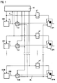
- the output signals of the Hall elements HE1 - HE18 each fed to a switch S1 - S18, through which the output signals D1 - D18 either the input of memory modules SP1 - SP18 can be fed in or directly as output signals from the encoder to be provided. How many switches are to be provided depends on of the maximum speed V of the position change, that is the maximum Speed of the encoder, and the processing speed of the modules used.
- Each Hall element HE1 - HE18 is connected to a control line with a Control unit ST connected, which thereby each individual Hall element HE1 - HE18 can switch on and off. It is obvious that an off or deactivated Hall element has no current consumption and thus the power requirement is reduced by deactivating Hall elements becomes.
- Switches S1 - S18 are also connected to the Control unit ST connected and are switched by this. Farther are the memory modules SP1 - SP18 via one control line each directly connected to the control unit ST, or it becomes the control signal for the memory modules SP1 - SP18 from the control signal of the associated Hall elements HE1 - HE18 by a time delay ⁇ t generated.
- control unit ST of the encoder to the supply voltage was connected, the control unit ST determined by querying each Hall element HE1 - HE18 in a specific, stored order the absolute position of the encoder.
- the control unit ST deactivates via the respective control lines the Hall elements HE2 - HE18 and activates the Hall element HE1. This happens at time t1, as can be seen in FIG. 3a, where the Control signals from the control unit ST for the Hall elements HE1-HE4 via the time are plotted.
- the switches S1 - S18 are first switched by the control unit ST in such a way that that the output signals D1 - D18 of the Hall elements HE1 - HE18 to the memory modules SP1 - SP18.
- control unit ST repeats this process for the next one Hall element HE2. This is done by the control unit ST at time t2 is activated and the assigned memory module SP2 is delayed also activated. Then the output signal D2 of the Hall element HE2 stored in the memory module SP2 and that Hall element HE2 is deactivated by control unit ST at time t3. This process is repeated until the output signals of all Hall elements HE1 - HE18 in the respectively assigned memory module SP1 - SP18 have been saved.
- the memory modules SP1 - SP18 are advantageously carried out as flip-flops, which the stored bit do not change until reactivation and as the output signal of the Provide the encoder in parallel form.
- the absolute Position determination also the number of revolutions of the optical division be counted by the control unit ST.
- Another alternative is to close the next Hall element already to activate a time t2 before the previous Hall element HE1 was deactivated at time t3, as shown in FIG. 3b. Thereby the Hall elements and assigned memory modules are successively activated, it is not waited until the previously activated Hall element was deactivated, so that several Hall elements with associated memory modules activated overlapping in time. This allows any Compromise between processing speed and low Achieve power consumption, depending on how many Hall elements at the same time are activated. This alternative is also for every combination of Hall element and memory module to provide a separate data line.
- control unit ST fed a signal indicating the speed V of the position change, the angular velocity for a rotary encoder, quantified.
- This signal can be, for example, the output signal D1 of the first Hall element Be HE1.
- the control unit ST compares whether the speed V of the position change is greater than a first threshold value Vmax1. If so is, the control unit ST sends a control signal to the switch S1 output, which switches the switch S1, whereby the memory module SP1 is bridged. It then becomes the output signal D1 of the Hall element HE1 is output without intermediate storage. It can be connected to the memory module SP1, which is now not required Control unit ST a signal for their deactivation are output.
- the first threshold value Vmax1 is selected such that at its Exceed the speed V of the position change is so great that intermediate storage is no longer necessary because of the output signal D1 is permanently present.
- the first threshold value Vmax1 has been exceeded, a check is carried out to determine whether a second threshold value Vmax2 is also exceeded. If that is the case the second switch S2 is also switched over, as a result of which the memory module SP2 is bridged. The output signal then also becomes immediate D2 of the Hall element HE2 is output without intermediate storage. It can also be connected to the SP2 memory module, which is now not required the control unit ST outputs a signal to deactivate it will.
- the second threshold Vmax2 becomes similar to the first Threshold value Vmax1 selected so that when it is exceeded, the speed V of the change in position is so large that an intermediate storage is no longer required because the output signal D1 is permanent is present. As a rule, the second threshold value Vmax2 becomes twice as large be like the first threshold Vmax1 because of the change in the magnetic field at the Hall element HE1 has twice the frequency as the change in Magnetic field at the Hall element HE2.
- This process of switching the output signals from Hall elements can be performed for all Hall elements HE1 to HE18 that are due to the maximum speed provided for the encoder is practical permanently output an output signal and therefore no intermediate storage is required.
- the other required threshold values Vmax3, Vmax4, etc. become twice as much according to the example above large as the previous threshold value selected.
- a further advantageous embodiment consists in providing a plurality of magnetic divisions T, as a result of which the resolution and / or value range of the rotary encoder can be expanded by a factor of 2 for each additional division track.
- the rotary movement is reduced by a gear according to the number of graduation tracks present or, if appropriate, also translated if the graduation is arranged accordingly.
- the speed must be passed on to the next graduation T, reduced by a factor of 2, for each graduation track using a digital code. If four division tracks TS1-TS4 are provided on a first division T, the rotational movement of this first division T for a second division T must be reduced by a factor of 2 4 .
- the frequency with which the individual Hall elements HE1 - HE18 are activated output signals are selected depending on the frequency. Since the output signal of the Hall element HE1 has the greatest frequency, it is activated most often and therefore occurs in the order of Hall elements activated essentially sequentially by the control unit ST most often on.
- the output signal of the Hall element HE2 points half the frequency of the output signal of the Hall element HE 1 on and therefore occurs in order only half as often as the Hall element HE1. The same applies to the other Hall elements. With the additional condition, that two activations of the same Hall element HE1 - HE18 should always be at the same time interval from each other the order in which the control unit ST the individual Hall elements HE1 - HE18 activated.
Landscapes
- Physics & Mathematics (AREA)
- General Physics & Mathematics (AREA)
- Transmission And Conversion Of Sensor Element Output (AREA)
- Analogue/Digital Conversion (AREA)
- Measurement Of Length, Angles, Or The Like Using Electric Or Magnetic Means (AREA)
- Arrangements For Transmission Of Measured Signals (AREA)
- Selective Calling Equipment (AREA)
- Radar Systems Or Details Thereof (AREA)
Applications Claiming Priority (2)
| Application Number | Priority Date | Filing Date | Title |
|---|---|---|---|
| DE19709087 | 1997-03-06 | ||
| DE19709087A DE19709087A1 (de) | 1997-03-06 | 1997-03-06 | Schaltungsanordnung und Verfahren zum Betrieb für einen Positionsgeber mit Hall-Elementen |
Publications (2)
| Publication Number | Publication Date |
|---|---|
| EP0863384A1 true EP0863384A1 (fr) | 1998-09-09 |
| EP0863384B1 EP0863384B1 (fr) | 2002-11-06 |
Family
ID=7822390
Family Applications (1)
| Application Number | Title | Priority Date | Filing Date |
|---|---|---|---|
| EP98103698A Expired - Lifetime EP0863384B1 (fr) | 1997-03-06 | 1998-03-03 | Circuit et procédé d'opération d'un capteur de position utilisant des éléments à effet Hall |
Country Status (5)
| Country | Link |
|---|---|
| US (1) | US6320373B1 (fr) |
| EP (1) | EP0863384B1 (fr) |
| JP (1) | JP4111357B2 (fr) |
| AT (1) | ATE227418T1 (fr) |
| DE (2) | DE19709087A1 (fr) |
Cited By (5)
| Publication number | Priority date | Publication date | Assignee | Title |
|---|---|---|---|---|
| WO2001098736A1 (fr) * | 2000-06-23 | 2001-12-27 | Sensirion Ag | Compteur de gaz et procede de determination d'une quantite de gaz consommee |
| CN101443632A (zh) * | 2006-05-12 | 2009-05-27 | 株式会社安川电机 | 磁性编码装置 |
| CN113439198A (zh) * | 2019-02-26 | 2021-09-24 | 大陆汽车有限公司 | 用于授权对具有抗磁干扰性的热力发动机的磁传感器进行更新的方法 |
| DE102011050834B4 (de) | 2011-06-03 | 2022-02-17 | Ic - Haus Gmbh | Integrierte Schaltungsanordnung mit Hallsensoren und Positionsmessvorrichtung |
| CN113439198B (zh) * | 2019-02-26 | 2024-05-28 | 大陆汽车科技有限公司 | 用于授权对具有抗磁干扰性的热力发动机的磁传感器进行更新的方法 |
Families Citing this family (13)
| Publication number | Priority date | Publication date | Assignee | Title |
|---|---|---|---|---|
| DE19849108C2 (de) * | 1998-10-24 | 2001-12-13 | Fritz Kuebler Gmbh Zaehl Und S | Drehgeber |
| DE19915988A1 (de) | 1999-04-09 | 2000-10-12 | Pierburg Ag | Messeinrichtung zur Ermittlung der Stellung eines Stellorgans |
| US7317313B2 (en) * | 2002-11-14 | 2008-01-08 | Measurement Specialties, Inc. | Magnetic encoder apparatus |
| DE10311412B3 (de) * | 2003-03-13 | 2004-05-27 | Lenord, Bauer & Co. Gmbh | Verfahren zur Messung und Bestimmung der absoluten Position einer Geberwelle sowie einer Einrichtung zur Anwendung des Verfahrens |
| JP2005093420A (ja) * | 2003-08-08 | 2005-04-07 | Omron Corp | 入力装置、これを用いた電子機器および携帯電話機 |
| US7948231B2 (en) | 2004-12-14 | 2011-05-24 | Ntn Corporation | Rotation detecting apparatus having magnetic sensor array and bearing provided with same |
| JP4553714B2 (ja) * | 2004-12-14 | 2010-09-29 | Ntn株式会社 | 回転検出装置および回転検出装置付き軸受 |
| US7633177B2 (en) * | 2005-04-14 | 2009-12-15 | Natural Forces, Llc | Reduced friction wind turbine apparatus and method |
| EP2365411A1 (fr) * | 2010-03-10 | 2011-09-14 | Sensirion AG | Agencement de contrôle de débit |
| US20120242320A1 (en) * | 2011-03-22 | 2012-09-27 | Fischer Kevin C | Automatic Generation And Analysis Of Solar Cell IV Curves |
| RU2567090C1 (ru) * | 2014-06-10 | 2015-10-27 | Федеральное государственное бюджетное учреждение "3 Центральный научно-исследовательский институт" Министерства обороны Российской Федерации | Датчик измерения параметров углового перемещения |
| JP6623621B2 (ja) * | 2014-11-26 | 2019-12-25 | サンケン電気株式会社 | モータ駆動装置 |
| EP3118640B1 (fr) * | 2015-07-13 | 2021-06-23 | ams AG | Capteur à effet hall |
Citations (3)
| Publication number | Priority date | Publication date | Assignee | Title |
|---|---|---|---|---|
| US4728950A (en) * | 1984-04-16 | 1988-03-01 | Telemeter Corporation | Magnetic sensor apparatus for remotely monitoring a utility meter or the like |
| EP0331828A1 (fr) * | 1986-09-29 | 1989-09-13 | Kabushiki Kaisha Yaskawa Denki Seisakusho | Codeur absolu de type multirotationnel |
| EP0620647A2 (fr) * | 1993-04-14 | 1994-10-19 | Namco Controls Corporation | Commutateur de proximité magnétique |
Family Cites Families (7)
| Publication number | Priority date | Publication date | Assignee | Title |
|---|---|---|---|---|
| DE3584256D1 (de) | 1984-04-14 | 1991-10-31 | Fanuc Ltd | Schaltungsmittel zur auswertung der bewegung einer inkrementalcodespur. |
| US5258735A (en) * | 1991-10-28 | 1993-11-02 | Allwine Jr Elmer C | Multi-pole composite magnet used in a magnetic encoder |
| US5528218A (en) * | 1992-07-22 | 1996-06-18 | Grote Industries, Inc. | Electronic self-canceling turn signal device |
| EP0590222A1 (fr) * | 1992-09-30 | 1994-04-06 | STMicroelectronics S.r.l. | Capteur de position magnétique |
| DE4442371A1 (de) | 1994-11-29 | 1996-05-30 | Heidenhain Gmbh Dr Johannes | Maßverkörperung |
| FR2760162A1 (fr) * | 1997-02-25 | 1998-08-28 | Philips Electronics Nv | Equipement de telecommunication muni d'un dispositif de reconnaissance magnetique de peripheriques |
| US5969495A (en) * | 1997-12-31 | 1999-10-19 | Daewood Heavy Industries Ltd. | Accelerator device for electromotive vehicles |
-
1997
- 1997-03-06 DE DE19709087A patent/DE19709087A1/de not_active Withdrawn
-
1998
- 1998-03-03 EP EP98103698A patent/EP0863384B1/fr not_active Expired - Lifetime
- 1998-03-03 AT AT98103698T patent/ATE227418T1/de not_active IP Right Cessation
- 1998-03-03 DE DE59806137T patent/DE59806137D1/de not_active Expired - Lifetime
- 1998-03-04 JP JP05242498A patent/JP4111357B2/ja not_active Expired - Fee Related
- 1998-03-06 US US09/036,168 patent/US6320373B1/en not_active Expired - Fee Related
Patent Citations (3)
| Publication number | Priority date | Publication date | Assignee | Title |
|---|---|---|---|---|
| US4728950A (en) * | 1984-04-16 | 1988-03-01 | Telemeter Corporation | Magnetic sensor apparatus for remotely monitoring a utility meter or the like |
| EP0331828A1 (fr) * | 1986-09-29 | 1989-09-13 | Kabushiki Kaisha Yaskawa Denki Seisakusho | Codeur absolu de type multirotationnel |
| EP0620647A2 (fr) * | 1993-04-14 | 1994-10-19 | Namco Controls Corporation | Commutateur de proximité magnétique |
Cited By (6)
| Publication number | Priority date | Publication date | Assignee | Title |
|---|---|---|---|---|
| WO2001098736A1 (fr) * | 2000-06-23 | 2001-12-27 | Sensirion Ag | Compteur de gaz et procede de determination d'une quantite de gaz consommee |
| CN101443632A (zh) * | 2006-05-12 | 2009-05-27 | 株式会社安川电机 | 磁性编码装置 |
| CN101443632B (zh) * | 2006-05-12 | 2010-10-13 | 株式会社安川电机 | 磁性编码装置 |
| DE102011050834B4 (de) | 2011-06-03 | 2022-02-17 | Ic - Haus Gmbh | Integrierte Schaltungsanordnung mit Hallsensoren und Positionsmessvorrichtung |
| CN113439198A (zh) * | 2019-02-26 | 2021-09-24 | 大陆汽车有限公司 | 用于授权对具有抗磁干扰性的热力发动机的磁传感器进行更新的方法 |
| CN113439198B (zh) * | 2019-02-26 | 2024-05-28 | 大陆汽车科技有限公司 | 用于授权对具有抗磁干扰性的热力发动机的磁传感器进行更新的方法 |
Also Published As
| Publication number | Publication date |
|---|---|
| EP0863384B1 (fr) | 2002-11-06 |
| JP4111357B2 (ja) | 2008-07-02 |
| DE59806137D1 (de) | 2002-12-12 |
| ATE227418T1 (de) | 2002-11-15 |
| US6320373B1 (en) | 2001-11-20 |
| JPH10300513A (ja) | 1998-11-13 |
| DE19709087A1 (de) | 1998-09-10 |
Similar Documents
| Publication | Publication Date | Title |
|---|---|---|
| EP0863384B1 (fr) | Circuit et procédé d'opération d'un capteur de position utilisant des éléments à effet Hall | |
| DE4209629B4 (de) | Absolutkodierer | |
| DE19641035C2 (de) | Vorrichtung und Verfahren zur Positionsmessung | |
| DE102008015837A1 (de) | Positionsmessgerät und Verfahren zu dessen Betrieb | |
| EP1193472A2 (fr) | Procédé et appareil pour la détermination de la position absolue des capteurs de déplacements et d'angles | |
| DE102004002722A1 (de) | Absoluter Codierer, der auf einem inkrementalen Codierer beruht | |
| DE3221982A1 (de) | Optisches inkrementalcodiersystem mit adressierbarem index | |
| DE102008057474B4 (de) | Meßumformer | |
| DE102005043489B4 (de) | Automatisierungstechnische Einrichtung | |
| EP0550794B1 (fr) | Codeur de rotation avec détection de valeur absolue de position | |
| EP1853927B1 (fr) | Detecteur de mouvement equipé d'un circuit de surveillance d'un encodeur et procede correspondent de surveillance d'un encodeur | |
| EP1206684B1 (fr) | Dispositif de mesure de position | |
| EP0581932B1 (fr) | Detecteur d'angle de rotation visant a proceder a la mesure absolue de l'angle de rotation sur plusieurs tours | |
| EP0406627B1 (fr) | Dispositif d'identification pour capteurs | |
| EP0943920A2 (fr) | Dispositif à capteur et procédé de transmission de données utilisant un tel dispositif à capteur | |
| EP1914522B1 (fr) | Procédé et dispositif destinés à la détermination de la position d'une unité d'entraînement | |
| DE4228899A1 (de) | Verfahren und Vorrichtung zur Kommutierung | |
| EP1321743B1 (fr) | Système pour mesurer une longueur absolue comprenant une barre de mesure qui se déplace relativement par rapport à des sondes de longueur mutuellement espacées | |
| DE3928027C2 (de) | Absolutkodierer | |
| DE102005043488A1 (de) | Automatisierungstechnische Einrichtung | |
| EP0566923B1 (fr) | Dispositif pour mesurer sans contact la position axiale d'un objet tournant | |
| EP0467196B1 (fr) | Dispositif de décodage | |
| DE4422868C2 (de) | Vorrichtung zum Bestimmen eines Drehwinkels eines Magneten | |
| WO1991012668A1 (fr) | Procede de conversion d'une tension analogique en valeur numerique | |
| DE2722581C3 (de) | Schaltungsanordnung zur Signalaufbereitung von Ausgangssignalen eines Feldplattengebers bei Raddrehzahlgebern von Fahrzeugen |
Legal Events
| Date | Code | Title | Description |
|---|---|---|---|
| PUAI | Public reference made under article 153(3) epc to a published international application that has entered the european phase |
Free format text: ORIGINAL CODE: 0009012 |
|
| 17P | Request for examination filed |
Effective date: 19980701 |
|
| AK | Designated contracting states |
Kind code of ref document: A1 Designated state(s): AT CH DE FR GB IT LI |
|
| AKX | Designation fees paid |
Free format text: AT CH DE FR GB IT LI |
|
| RBV | Designated contracting states (corrected) |
Designated state(s): AT CH DE FR GB IT LI |
|
| GRAG | Despatch of communication of intention to grant |
Free format text: ORIGINAL CODE: EPIDOS AGRA |
|
| GRAG | Despatch of communication of intention to grant |
Free format text: ORIGINAL CODE: EPIDOS AGRA |
|
| GRAH | Despatch of communication of intention to grant a patent |
Free format text: ORIGINAL CODE: EPIDOS IGRA |
|
| 17Q | First examination report despatched |
Effective date: 20020510 |
|
| GRAH | Despatch of communication of intention to grant a patent |
Free format text: ORIGINAL CODE: EPIDOS IGRA |
|
| GRAA | (expected) grant |
Free format text: ORIGINAL CODE: 0009210 |
|
| AK | Designated contracting states |
Kind code of ref document: B1 Designated state(s): AT CH DE FR GB IT LI |
|
| REF | Corresponds to: |
Ref document number: 227418 Country of ref document: AT Date of ref document: 20021115 Kind code of ref document: T |
|
| REG | Reference to a national code |
Ref country code: GB Ref legal event code: FG4D Free format text: NOT ENGLISH |
|
| REG | Reference to a national code |
Ref country code: CH Ref legal event code: NV Representative=s name: TROESCH SCHEIDEGGER WERNER AG Ref country code: CH Ref legal event code: EP |
|
| REF | Corresponds to: |
Ref document number: 59806137 Country of ref document: DE Date of ref document: 20021212 |
|
| GBT | Gb: translation of ep patent filed (gb section 77(6)(a)/1977) |
Effective date: 20030205 |
|
| ET | Fr: translation filed | ||
| PLBE | No opposition filed within time limit |
Free format text: ORIGINAL CODE: 0009261 |
|
| STAA | Information on the status of an ep patent application or granted ep patent |
Free format text: STATUS: NO OPPOSITION FILED WITHIN TIME LIMIT |
|
| 26N | No opposition filed |
Effective date: 20030807 |
|
| PGFP | Annual fee paid to national office [announced via postgrant information from national office to epo] |
Ref country code: AT Payment date: 20090317 Year of fee payment: 12 |
|
| PGFP | Annual fee paid to national office [announced via postgrant information from national office to epo] |
Ref country code: IT Payment date: 20090324 Year of fee payment: 12 |
|
| PGFP | Annual fee paid to national office [announced via postgrant information from national office to epo] |
Ref country code: FR Payment date: 20090312 Year of fee payment: 12 |
|
| PG25 | Lapsed in a contracting state [announced via postgrant information from national office to epo] |
Ref country code: AT Free format text: LAPSE BECAUSE OF NON-PAYMENT OF DUE FEES Effective date: 20100303 |
|
| REG | Reference to a national code |
Ref country code: FR Ref legal event code: ST Effective date: 20101130 |
|
| PG25 | Lapsed in a contracting state [announced via postgrant information from national office to epo] |
Ref country code: FR Free format text: LAPSE BECAUSE OF NON-PAYMENT OF DUE FEES Effective date: 20100331 |
|
| PG25 | Lapsed in a contracting state [announced via postgrant information from national office to epo] |
Ref country code: IT Free format text: LAPSE BECAUSE OF NON-PAYMENT OF DUE FEES Effective date: 20100303 |
|
| PGFP | Annual fee paid to national office [announced via postgrant information from national office to epo] |
Ref country code: DE Payment date: 20140319 Year of fee payment: 17 Ref country code: CH Payment date: 20140319 Year of fee payment: 17 |
|
| PGFP | Annual fee paid to national office [announced via postgrant information from national office to epo] |
Ref country code: GB Payment date: 20140319 Year of fee payment: 17 |
|
| REG | Reference to a national code |
Ref country code: DE Ref legal event code: R119 Ref document number: 59806137 Country of ref document: DE |
|
| REG | Reference to a national code |
Ref country code: CH Ref legal event code: PL |
|
| GBPC | Gb: european patent ceased through non-payment of renewal fee |
Effective date: 20150303 |
|
| PG25 | Lapsed in a contracting state [announced via postgrant information from national office to epo] |
Ref country code: LI Free format text: LAPSE BECAUSE OF NON-PAYMENT OF DUE FEES Effective date: 20150331 Ref country code: GB Free format text: LAPSE BECAUSE OF NON-PAYMENT OF DUE FEES Effective date: 20150303 Ref country code: CH Free format text: LAPSE BECAUSE OF NON-PAYMENT OF DUE FEES Effective date: 20150331 Ref country code: DE Free format text: LAPSE BECAUSE OF NON-PAYMENT OF DUE FEES Effective date: 20151001 |