EP0581932B1 - Detecteur d'angle de rotation visant a proceder a la mesure absolue de l'angle de rotation sur plusieurs tours - Google Patents
Detecteur d'angle de rotation visant a proceder a la mesure absolue de l'angle de rotation sur plusieurs tours Download PDFInfo
- Publication number
- EP0581932B1 EP0581932B1 EP93903906A EP93903906A EP0581932B1 EP 0581932 B1 EP0581932 B1 EP 0581932B1 EP 93903906 A EP93903906 A EP 93903906A EP 93903906 A EP93903906 A EP 93903906A EP 0581932 B1 EP0581932 B1 EP 0581932B1
- Authority
- EP
- European Patent Office
- Prior art keywords
- angle
- rotation
- sensor
- sensor elements
- analog
- Prior art date
- Legal status (The legal status is an assumption and is not a legal conclusion. Google has not performed a legal analysis and makes no representation as to the accuracy of the status listed.)
- Expired - Lifetime
Links
Images


Classifications
-
- H—ELECTRICITY
- H03—ELECTRONIC CIRCUITRY
- H03M—CODING; DECODING; CODE CONVERSION IN GENERAL
- H03M1/00—Analogue/digital conversion; Digital/analogue conversion
- H03M1/06—Continuously compensating for, or preventing, undesired influence of physical parameters
- H03M1/0617—Continuously compensating for, or preventing, undesired influence of physical parameters characterised by the use of methods or means not specific to a particular type of detrimental influence
- H03M1/0619—Continuously compensating for, or preventing, undesired influence of physical parameters characterised by the use of methods or means not specific to a particular type of detrimental influence by dividing out the errors, i.e. using a ratiometric arrangement
-
- G—PHYSICS
- G01—MEASURING; TESTING
- G01D—MEASURING NOT SPECIALLY ADAPTED FOR A SPECIFIC VARIABLE; ARRANGEMENTS FOR MEASURING TWO OR MORE VARIABLES NOT COVERED IN A SINGLE OTHER SUBCLASS; TARIFF METERING APPARATUS; MEASURING OR TESTING NOT OTHERWISE PROVIDED FOR
- G01D5/00—Mechanical means for transferring the output of a sensing member; Means for converting the output of a sensing member to another variable where the form or nature of the sensing member does not constrain the means for converting; Transducers not specially adapted for a specific variable
- G01D5/12—Mechanical means for transferring the output of a sensing member; Means for converting the output of a sensing member to another variable where the form or nature of the sensing member does not constrain the means for converting; Transducers not specially adapted for a specific variable using electric or magnetic means
- G01D5/14—Mechanical means for transferring the output of a sensing member; Means for converting the output of a sensing member to another variable where the form or nature of the sensing member does not constrain the means for converting; Transducers not specially adapted for a specific variable using electric or magnetic means influencing the magnitude of a current or voltage
- G01D5/20—Mechanical means for transferring the output of a sensing member; Means for converting the output of a sensing member to another variable where the form or nature of the sensing member does not constrain the means for converting; Transducers not specially adapted for a specific variable using electric or magnetic means influencing the magnitude of a current or voltage by varying inductance, e.g. by a movable armature
- G01D5/204—Mechanical means for transferring the output of a sensing member; Means for converting the output of a sensing member to another variable where the form or nature of the sensing member does not constrain the means for converting; Transducers not specially adapted for a specific variable using electric or magnetic means influencing the magnitude of a current or voltage by varying inductance, e.g. by a movable armature by influencing the mutual induction between two or more coils
- G01D5/2086—Mechanical means for transferring the output of a sensing member; Means for converting the output of a sensing member to another variable where the form or nature of the sensing member does not constrain the means for converting; Transducers not specially adapted for a specific variable using electric or magnetic means influencing the magnitude of a current or voltage by varying inductance, e.g. by a movable armature by influencing the mutual induction between two or more coils by movement of two or more coils with respect to two or more other coils
-
- H—ELECTRICITY
- H03—ELECTRONIC CIRCUITRY
- H03M—CODING; DECODING; CODE CONVERSION IN GENERAL
- H03M1/00—Analogue/digital conversion; Digital/analogue conversion
- H03M1/12—Analogue/digital converters
- H03M1/64—Analogue/digital converters with intermediate conversion to phase of sinusoidal or similar periodical signals
- H03M1/645—Analogue/digital converters with intermediate conversion to phase of sinusoidal or similar periodical signals for position encoding, e.g. using resolvers or synchros
Definitions
- the invention relates to a rotation angle sensor according to the preamble of claim 1.
- Known sensors are used to determine rotational angle positions of rotating parts e.g. B. to measure a motor shaft absolutely over several revolutions. Their technical function is that, unlike incremental and counting sensors, they operate in any operating state, e.g. B. after switching on or after malfunctions, output the correct angular position.
- a rotation angle sensor of this type is known from the company lettering IMAS (Inductive Modular Absolute Measurement System) EUCRON, Leinfelden-Echterdingen and consists of coarse and fine rotation angle sensor elements, which are successively coupled via gears.
- IMAS Inductive Modular Absolute Measurement System
- EUCRON Inductive Modular Absolute Measurement System
- Leinfelden-Echterdingen consists of coarse and fine rotation angle sensor elements, which are successively coupled via gears.
- the control of the multiplexer and thus the selection of an individual sensor element takes place by means of different DC voltage levels which are superimposed on the sensor element excitation voltage supplied to the multiplexer by the evaluation circuit.
- the multiplexer is implemented with the aid of semiconductor components such as semiconductor switches for switching the sensor signals and comparators for detecting the DC voltage control level.
- the auxiliary energy for multiplexer control is derived from the sensor element excitation voltage with the help of rectifiers.
- the disadvantage of this angle of rotation sensor is the integration of semiconductor components at the measurement location. These make the sensor sensitive to environmental influences such as electrical and magnetic interference fields as well as extreme temperature fluctuations, which are common in applications in the field of drive technology.
- Another angle of rotation sensor is described in DE 37 34 938 A1.
- the arrangement provides for a number of resolvers coupled to one another via gears.
- the gear ratios are defined with 2EXP (N).
- the code is one step.
- the angle information of the individual sensor elements is linked via a redundant bit.
- the disadvantage of this arrangement is the restriction to certain gear ratios of the gearbox due to the evaluation circuit. This makes it difficult to optimize them for advantageous small designs.
- Another disadvantage is the commitment to a one-step code. For processing in control units customary in industry, this must be converted into the natural dual code by means of a code converter.
- a further disadvantage is the restriction to only one bit position due to an evaluation circuit for linking the angle information of the individual sensor elements. This limits the tolerances for the gearless gearboxes to 1/4 turn of the preceding shaft. The mechanical effort for the implementation of the gearbox is therefore higher than necessary.
- Another disadvantage is that of the exclusive Use of resolvers incurred costs.
- Another sensor is known from DE 32 46 959. In it, several sensor elements are coupled in series via differential gears with small reduction ratios. The disadvantage of using differential gears on fast rotating input shafts is the high rotor speed of the sensor elements following one after the other. This demands their storage and requires a complex mechanical design.
- Optical absolute angle sensors and capacitive angle sensors are known from DE 29 38 318 and DE 37 11 062. They use glass panes with optically coded divisions or fixed and rotating capacitor plates for coding angle information.
- the disadvantage of optical and capacitive sensors is their sensitivity to electrical and magnetic interference fields as well as extreme temperature fluctuations due to the integrated signal electronics.
- Another disadvantage of the optical sensors is the sensitivity of the glass panes to shocks and dirt.
- the invention has for its object to provide a rotation angle sensor for measuring rotation angles over several revolutions, which with good resolution compared to electrical, magnetic, electromagnetic, thermal and radioactive interference as well as mechanical shocks is largely unaffected.
- toroidal chokes are used as switching elements of the time-division multiplexing device.
- inductive switching elements to implement the multiplex technology advantageously enables the wiring effort to be saved without impairing the robustness or sensitivity of the sensor.
- the toroidal chokes have a switching winding and a switched winding.
- the magnetic material of the toroidal chokes has a magnetization curve with sections of approximately constant, high differential permeability and approximately constant, low differential permeability. This enables by forming sufficiently high inductive resistors in the switched-off or blocked state and by forming sufficiently low inductive resistors in the resp. switched state to use the chokes as switch elements for AC voltages.
- the magnetic material of the toroidal chokes has a low coercive force. This makes it possible to keep the distortion of the AC voltage to be switched low when the inductor is "on".
- the electronic evaluation circuit connected to the sensor via connecting lines can be arranged remotely from the measuring location. This advantageously enables the evaluation circuit, which is sensitive to environmental influences, in a control cabinet to accommodate.
- the angle of rotation sensor advantageously consists exclusively of inductive components and is therefore particularly robust or stable with regard to its electromagnetic, thermal and mechanical environmental compatibility.
- the digital angle information of resolver and downstream sensor elements is linked by an electronic evaluation circuit. Since the analog / digital conversion of the angle values of the coarse sensor elements is carried out with the same resolution as for the fine sensor elements, there is more than just one redundant information bit available for the link calculation. This enables a greater tolerance due to gearless ( ⁇ 1/2 turn of the gearbox input shaft compared to ⁇ 1/4 turn when only one redundant information bit is used) or a higher reduction ratio for a certain tolerance due to gearless. Furthermore, the increased resolution of the angle information of the coarse sensor elements makes it possible to detect errors, which allows the degree of wear of the transmission to be recognized. Due to the program-controlled evaluation circuit, there is no restriction of the gear ratio to certain or identical gear ratios. This advantageously enables the mechanical size of the transmission to be minimized. All angle sensor elements are evaluated depending on the operating state, e.g. B. when switching on the supply voltage. In normal operation, only the fine-angle sensor element is evaluated and the number of complete revolutions is determined incrementally by carry counting.
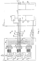
- a resolver 3 serves as the first fine angle sensor element of the rotation angle sensor and is directly coupled to a working shaft 2 whose mechanical angular position is to be measured.
- a plurality of coarse-angle sensor elements 5, 7 are successively coupled to the shaft via reduction gears 4, 6.
- An excitation alternating voltage Ue (i) is supplied to each of the sensor elements 3, 5, 7 via two input lines Le1 (i), Le2 (i).
- Each of the sensor elements 3, 5, 7 outputs an output voltage Usin (i) via two output lines Ls1 (i), Ls2 (i) and an output voltage Ucos (i) via a further two output lines Lc1 (i), Lc2 (i).
- the input and output lines of the sensor elements 3, 5, 7 are connected to a multiplexer 8 which is preferably arranged in the angle of rotation sensor.
- the multiplexer 8 is connected to the electronic evaluation circuit 10 via a cable 9, which preferably has six connecting lines Le1, Le2, Ls1, Ls2, Lc1, Lc2 and a plurality of control lines S (i).
- the evaluation circuit 10 has an oscillator 11 for generating an excitation voltage Ue for the angle sensor elements, an analog-digital converter 12 for demodulation and analog-digital conversion of the sensor signals Usin and Ucos, a control circuit 13 for controlling the switching elements of the multiplexer, a programmable one Computing and control unit or CPU 14 for sequential evaluation of all signals of the angle sensor elements and a memory 15 for intermediate storage of the output signals of the individual sensor elements 3,5,7.
- the excitation alternating voltage supply lines Le1 and Le2 are connected to the oscillator 11, while the output lines which supply the output voltage Usin (i) and Ucos (i) are connected to the A / D converter 12 are.
- 16 denotes a driver circuit which has signal lines 17 on the output side, via which the absolute angle value is transmitted to a higher-level control and / or regulating unit.
- Fig. 1 it can be seen that the output signals of the sensor elements 3, 5, 7 are applied to the evaluation circuit 10 via, for example, six lines interconnected in the multiplexer 8, which processes the output signals of the angle of rotation sensor 1 after evaluation in order to use a control or regulating circuit to control or regulate the motor driving the working shaft 2, not shown in the drawing.
- the A / D converter 12 receives from the multiplexer 8 in the above-described embodiment, analog signals which are converted into digital signals.
- the computing and control unit 14 preferably receives the rotation angle information of the individual sensor elements 3, 5, 7 as binary words and effects an intermediate storage.
- the computing and control unit 14 combines the output signals of the sensor elements 3, 5, 7 in a manner known per se to form an absolute angle information, which preferably takes into account several working shaft revolutions.
- FIG. 3 A preferred embodiment of a switching element for the multiplexer 8 is illustrated in FIG. 3.
- a toroidal core 20 made of soft magnetic material contains a switching winding 21 and a switched winding 22, which are preferably wound opposite one another on the toroidal core 20 according to FIG. 3.
- a switching element S1 to S18 of the type described in connection with FIG. 3 is arranged in the multiplexer 8 of one of the line link nodes K1 to K6 shown there, whereby the output signals on lines Le1 (i) and Le2 (i), ... Lc2 (i) of the sensors 3, 5 and 7 are given to the evaluation circuit 10.
- the multiplexer 8 in the exemplary embodiment shown has six such switching elements per sensor, which depends on the number of input lines which are connected to the sensor elements 3, 5, 7.
- Fig. 4 shows the operation of the switching element based on the magnetization characteristic of the toroid.
- the use of toroidal chokes as a switching element requires large differences in the differential permeability in the individual operating points on the magnetization characteristic curve with at the same time low magnetic reversal losses. This is achieved by using soft magnetic magnetic material with a Z-shaped magnetization characteristic.
- the magnetization curve which indicates the magnetic flux density B as a function of the magnetic field strength H, has an approximately rectilinear, steep section 23 and two approximately rectilinear, flat sections 24, 25.
- the coercive field strength of the toroidal material is low. This means that the magnetic material of the toroidal core is almost free of hysteresis and generates low magnetic loss.
- the switching effect of the switched winding 22 is achieved by changing its inductive resistance. This is achieved by pre-magnetizing the toroid through a control current generated magnetic field of the switching winding 21. With the switching winding deenergized, the operating point 'OFF' 26 of the switched winding 22 lies in the coordinate origin of the magnetization characteristic with a large differential permeability. This results in a high inductive resistance for the switching state 'OFF'. If a sufficiently large direct current flows through the switching winding 21, an operating point 'ON' 27 of the switched winding results on the flat part of the characteristic curve with low differential permeability due to the premagnetization. This results in a correspondingly low inductive resistance for the 'ON' switching state.
- the controlled coil 22 is operated exclusively in the two predefined operating points 'ON' and 'OFF'.
- the voltage drop across the impedance of the switched winding 22 in its switched-on state falsifies the measurement signal voltages. Due to the ratiometric evaluation of the signals Usin (i) and Ucos (i), this as well as the error caused by the resistance of the supply line are eliminated.
- FIG. 5 shows an embodiment of the connection of two sensor elements 28, 29 with the output voltages Usin (1), Ucos (1) and Usin (2), Ucos (2) and the excitation voltages Ue (1) and Ue (2).
- One of the two groups 30, 31, each with six inductive switching elements, is driven by currents via control lines 32, 34 and 33, 34.
- the output voltages of the selected sensor element 28 or 29 selected in this way are switched through to the connecting lines to the evaluation electronics 10 with a low resistance.
- FIG. 5 shows that the respective switching windings 21a, 21b to 21f or 21a 'to 21f' are controlled by corresponding current signals on the control lines 32, 33, 34 and in this way the signals of the associated switched winding 22a , 22b, etc. are switched to pass.
- a switch-on signal on the control lines 32 and 34 thus causes the switching windings 21a, 21b etc. of the upper group of switching elements to be actuated and a switch-on control signal on the control lines 33 and 34 the control of the switching windings 21a ', 21b' etc. of the lower group in FIG. 5, the upper group in the sensor element 28 and the lower group being assigned to the sensor element 29.
- connection nodes of the individual lines are also labeled K1 to K6 in FIG. 5 in accordance with FIG. 1 and connect the output lines of the respective mutually associated switched windings 22 of the sensor elements.
- the voltage Usin is formed proportionately via the connection node K1-K2 from the addition of the voltages Usin (1) and Usin (2) according to the switching ratio SV of the switching elements involved.
- SV must be chosen large enough. This is done by selecting a suitable magnetic material and by dimensioning the windings of the switched toroidal coils (22a to 22f, 22a 'to 22f').
- the coercive field strength is a measure of the hysteresis of the magnetic material. Hysteresis affects the inductive resistance of the controlled coil for the switching state "OFF" of the switching element. Furthermore, through magnetic losses, energy is withdrawn from the measuring branch and the signal amplitude is thus weakened.
- the coercive field strength of the toroidal magnetic material must therefore be chosen small enough that the resulting measurement signal errors are of the order of magnitude of the measurement accuracy of the sensor elements.
- the evaluation circuit 10 is arranged at a distance from the measuring location, i.e. it is not in the immediate vicinity of the motor or the sensor elements.
Landscapes
- Engineering & Computer Science (AREA)
- Theoretical Computer Science (AREA)
- Physics & Mathematics (AREA)
- General Physics & Mathematics (AREA)
- Measurement Of Length, Angles, Or The Like Using Electric Or Magnetic Means (AREA)
- Transmission And Conversion Of Sensor Element Output (AREA)
Abstract
Claims (4)
- Détecteur d'angle de rotation pour la mesure absolue d'un angle de rotation sur plusieurs tours, comportant un résolveur connecté à l'arbre rotatif à contrôler comme élément de détection d'angle fine et plusieurs éléments inducteurs de détection grossière couplés respectivement via un démultiplicateur, un convertisseur analogique/numérique pour démoduler et convertir les signaux de sortie de tensions alternatives analogiques des éléments de détection inductifs en un mot de données binaires, un multiplexeur temporel qui achemine en séquence les signaux analogiques des éléments de détection individuels au convertisseur analogique/numérique, un circuit d'évaluation électronique qui bufférise les informations d'angle de rotation, présentes sous forme de mots binaires, données par les éléments de détection individuels et les combine en informations d'angle absolu sur plusieurs rotations, caractérisé en ce que l'on prévoit comme éléments de commutation du dispositif de multiplexage temporel des bobines toriques (21, 22) et en ce que les bobines toriques présentent un enroulement de commutation (24) et un enroulement commuté (22) par lesquels le signal analogique de l'élément de détection respectif est acheminé.
- Détecteur d'angle de rotation selon la revendication 1, caractérisé en ce que le matériau magnétique des bobines toriques (21, 22) présente une courbe d'aimantation avec des sections de perméabilité différentielle élevée approximativement constante et de perméabilité différentielle basse approximativement constante.
- Détecteur d'angle de rotation selon la revendication 1 ou 2, caractérisé en ce que le matériau magnétique des bobines toriques présente une force coercitive de faible intensité.
- Détecteur d'angle de rotation selon l'une quelconque des revendications précédentes, caractérisé en ce que le circuit d'évaluation (10) est agencé à distance du point de mesure.
Applications Claiming Priority (3)
| Application Number | Priority Date | Filing Date | Title |
|---|---|---|---|
| DE4203236 | 1992-02-05 | ||
| DE4203236 | 1992-02-05 | ||
| PCT/EP1993/000257 WO1993016354A1 (fr) | 1992-02-05 | 1993-02-04 | Detecteur d'angle de rotation visant a proceder a la mesure absolue de l'angle de rotation sur plusieurs tours |
Publications (2)
| Publication Number | Publication Date |
|---|---|
| EP0581932A1 EP0581932A1 (fr) | 1994-02-09 |
| EP0581932B1 true EP0581932B1 (fr) | 1996-02-28 |
Family
ID=6450985
Family Applications (1)
| Application Number | Title | Priority Date | Filing Date |
|---|---|---|---|
| EP93903906A Expired - Lifetime EP0581932B1 (fr) | 1992-02-05 | 1993-02-04 | Detecteur d'angle de rotation visant a proceder a la mesure absolue de l'angle de rotation sur plusieurs tours |
Country Status (5)
| Country | Link |
|---|---|
| US (1) | US5473237A (fr) |
| EP (1) | EP0581932B1 (fr) |
| JP (1) | JP3041645B2 (fr) |
| DE (2) | DE59301713D1 (fr) |
| WO (1) | WO1993016354A1 (fr) |
Families Citing this family (11)
| Publication number | Priority date | Publication date | Assignee | Title |
|---|---|---|---|---|
| US5684719A (en) * | 1995-06-07 | 1997-11-04 | Hughes Electronics | Software-based resolver-to-digital converter |
| DE19601676A1 (de) * | 1996-01-18 | 1997-07-24 | Teves Gmbh Alfred | Lenkwinkelsensor mit Auswertung der Inkrementalspur zur Absolutwertbestimmung |
| DE19601965A1 (de) * | 1996-01-20 | 1997-07-24 | Teves Gmbh Alfred | Lenkwinkelsensor mit Umdrehungszählwerk |
| DE19652935B4 (de) * | 1996-12-19 | 2005-04-21 | Valeo Schalter Und Sensoren Gmbh | Mit einem Resolver versehene Meßeinrichtung zur Messung des Lenkwinkels eines Fahrzeugs |
| GB9716658D0 (en) * | 1997-08-07 | 1997-10-15 | Lucas Ind Plc | Improvements relating to motors |
| DE19816471A1 (de) * | 1998-04-14 | 1999-10-28 | Elmeg | Vorrichtung zum Messen von mechanischen Bewegungen |
| JP2001208503A (ja) * | 2000-01-25 | 2001-08-03 | Harmonic Drive Syst Ind Co Ltd | リニアアクチュエータの絶対位置検出装置 |
| DE10118072B4 (de) * | 2000-05-17 | 2015-08-13 | Heidelberger Druckmaschinen Ag | Verfahren zur Sicherung der Gültigkeit und Verwaltung von motorspezifischen Daten |
| DE10158223B4 (de) * | 2001-11-16 | 2017-10-05 | Dr. Johannes Heidenhain Gmbh | Drehwinkel-Messgerät |
| CZ299293B6 (cs) * | 2004-05-07 | 2008-06-11 | Benda@Milan | Víceotáckový mechanicko-elektronický snímac polohy a/nebo stavu |
| DE102005055951A1 (de) | 2005-11-24 | 2007-05-31 | Robert Bosch Gmbh | Auswerteschaltung zur Verarbeitung von digitalen Signalen, Verfahren und Sensoranordnung |
Family Cites Families (15)
| Publication number | Priority date | Publication date | Assignee | Title |
|---|---|---|---|---|
| US3446982A (en) * | 1966-03-24 | 1969-05-27 | Amp Inc | Signal switching circuit |
| US3806785A (en) * | 1969-06-10 | 1974-04-23 | Anvar | Brushless d. c. electric machine |
| US3835375A (en) * | 1972-01-21 | 1974-09-10 | L Rovner | Apparatus for determining the direction of a magnetic field relative to a reference direction by synchronously scanning the field and a memory |
| US3875372A (en) * | 1974-02-01 | 1975-04-01 | Tappan Co | Control circuit for a self-cleaning oven |
| US4027213A (en) * | 1974-03-28 | 1977-05-31 | Valroger Pierre Albert Marie D | Electronic switching arrangement for energizing electric motors |
| US3950993A (en) * | 1975-04-02 | 1976-04-20 | Illinois Tool Works Inc. | Temperature sensors with improved operating characteristics utilizing magnetic elements |
| US4035805A (en) * | 1975-07-23 | 1977-07-12 | Scientific-Atlanta, Inc. | Satellite tracking antenna system |
| US4208550A (en) * | 1978-03-03 | 1980-06-17 | General Electric Company | Magnetic parallel-to-serial converter for gas turbine engine parameter sensor |
| DE2938318C2 (de) * | 1979-09-21 | 1988-05-26 | Dr. Johannes Heidenhain Gmbh, 8225 Traunreut | Meßeinrichtung |
| US4363999A (en) * | 1980-07-14 | 1982-12-14 | Preikschat F K | Electric propulsion and braking system for automotive vehicles |
| JPS58106691A (ja) * | 1981-12-21 | 1983-06-25 | 株式会社エスジ− | アブソリュート位置検出装置 |
| DE3711062A1 (de) * | 1987-04-02 | 1988-10-20 | Herbert Leypold | Kapazitive absolute positionsmessvorrichtung |
| DE3734938A1 (de) * | 1987-10-15 | 1989-05-03 | Stegmann Uhren Elektro | Sensoreinheit, insbesondere zum betrieb von elektrisch kommutierten synchronelektromotoren in servoregelkreisen |
| CH681655A5 (fr) * | 1989-12-06 | 1993-04-30 | Baumer Electric Ag | |
| US5161311A (en) * | 1990-08-29 | 1992-11-10 | Alps Electric Inc. | Calibration and compensation of an electronic compass system |
-
1993
- 1993-02-04 EP EP93903906A patent/EP0581932B1/fr not_active Expired - Lifetime
- 1993-02-04 US US08/122,589 patent/US5473237A/en not_active Expired - Lifetime
- 1993-02-04 DE DE59301713T patent/DE59301713D1/de not_active Expired - Fee Related
- 1993-02-04 WO PCT/EP1993/000257 patent/WO1993016354A1/fr active IP Right Grant
- 1993-02-04 JP JP5513744A patent/JP3041645B2/ja not_active Expired - Fee Related
- 1993-02-04 DE DE4303235A patent/DE4303235C2/de not_active Expired - Fee Related
Also Published As
| Publication number | Publication date |
|---|---|
| DE4303235A1 (en) | 1993-08-12 |
| JPH06507500A (ja) | 1994-08-25 |
| DE59301713D1 (de) | 1996-04-04 |
| WO1993016354A1 (fr) | 1993-08-19 |
| US5473237A (en) | 1995-12-05 |
| JP3041645B2 (ja) | 2000-05-15 |
| DE4303235C2 (de) | 1996-09-19 |
| EP0581932A1 (fr) | 1994-02-09 |
Similar Documents
| Publication | Publication Date | Title |
|---|---|---|
| AT404300B (de) | Drehgeber | |
| EP1241438B1 (fr) | Dispositif de mesure d'angle | |
| EP1193472B1 (fr) | Procédé et appareil pour la détermination de la position absolue des capteurs de déplacements et d'angles | |
| EP0581932B1 (fr) | Detecteur d'angle de rotation visant a proceder a la mesure absolue de l'angle de rotation sur plusieurs tours | |
| DE102008051083A1 (de) | Multiturn-Drehgeber | |
| DE102018218124A1 (de) | Kompakte pseudozufällige Skala und Lesekopf für einen Absolut-Positionsgeber induktiver Art | |
| EP0863384B1 (fr) | Circuit et procédé d'opération d'un capteur de position utilisant des éléments à effet Hall | |
| CH648120A5 (de) | Digitale elektrische laengen- oder winkelmesseinrichtung. | |
| WO2007025894A2 (fr) | Capteur de position et procede pour faire fonctionner un capteur de position | |
| DE3221982A1 (de) | Optisches inkrementalcodiersystem mit adressierbarem index | |
| DE3509763C2 (fr) | ||
| DE102005043489B4 (de) | Automatisierungstechnische Einrichtung | |
| EP2348326B1 (fr) | Unité de capteur de courant et procédé de transmission de signal et/ou de données | |
| EP1166049A1 (fr) | Composant electrique identifiable, procede d'identification et unite d'interpretation | |
| WO1988007658A1 (fr) | Procede et dispositif pour evaluer une grandeur electrique analogique | |
| DE19502276C2 (de) | Interpolationsverfahren und hochauflösende digitale Interpolationseinrichtung | |
| DE4422868C2 (de) | Vorrichtung zum Bestimmen eines Drehwinkels eines Magneten | |
| EP1399715B1 (fr) | Procede et dispositif permettant de preparer un signal d'un capteur de position en vue de sa transmission a une unite d'evaluation | |
| DE102006049755B4 (de) | Schaltungsanordnung zur Konvertierung von Sensorsignalen | |
| EP0220547A1 (fr) | Circuit pour capteur de mesure tachymétrique | |
| DE19835377A1 (de) | Vorrichtung zur Erfassung der Drehstellung, Drehzahl und/oder Drehrichtung des Rotors eines Elektromotors | |
| CH704584B1 (de) | Herstellungsverfahren für einen Codeträger mit einer absolutcodierten Codespur mit einer optimierten Anzahl von Teilungen. | |
| DE19506276B4 (de) | Verfahren und Schaltungsanordnung zur Interpolation von Sensorsignalen | |
| DE3513343C2 (fr) | ||
| EP2128569A2 (fr) | Capteur inductif et procédé de production d'un tel capteur |
Legal Events
| Date | Code | Title | Description |
|---|---|---|---|
| PUAI | Public reference made under article 153(3) epc to a published international application that has entered the european phase |
Free format text: ORIGINAL CODE: 0009012 |
|
| 17P | Request for examination filed |
Effective date: 19931004 |
|
| AK | Designated contracting states |
Kind code of ref document: A1 Designated state(s): CH DE FR GB IT LI |
|
| 17Q | First examination report despatched |
Effective date: 19950426 |
|
| GRAA | (expected) grant |
Free format text: ORIGINAL CODE: 0009210 |
|
| AK | Designated contracting states |
Kind code of ref document: B1 Designated state(s): CH DE FR GB IT LI |
|
| PG25 | Lapsed in a contracting state [announced via postgrant information from national office to epo] |
Ref country code: IT Free format text: LAPSE BECAUSE OF FAILURE TO SUBMIT A TRANSLATION OF THE DESCRIPTION OR TO PAY THE FEE WITHIN THE PRE;WARNING: LAPSES OF ITALIAN PATENTS WITH EFFECTIVE DATE BEFORE 2007 MAY HAVE OCCURRED AT ANY TIME BEFORE 2007. THE CORRECT EFFECTIVE DATE MAY BE DIFFERENT FROM THE ONE RECORDED.SCRIBED TIME-LIMIT Effective date: 19960228 |
|
| REF | Corresponds to: |
Ref document number: 59301713 Country of ref document: DE Date of ref document: 19960404 |
|
| GBT | Gb: translation of ep patent filed (gb section 77(6)(a)/1977) |
Effective date: 19960307 |
|
| ET | Fr: translation filed | ||
| PLBE | No opposition filed within time limit |
Free format text: ORIGINAL CODE: 0009261 |
|
| STAA | Information on the status of an ep patent application or granted ep patent |
Free format text: STATUS: NO OPPOSITION FILED WITHIN TIME LIMIT |
|
| 26N | No opposition filed | ||
| REG | Reference to a national code |
Ref country code: CH Ref legal event code: PL |
|
| PGFP | Annual fee paid to national office [announced via postgrant information from national office to epo] |
Ref country code: CH Payment date: 19971201 Year of fee payment: 5 |
|
| REG | Reference to a national code |
Ref country code: CH Ref legal event code: AEN Free format text: DAS PATENT IST AUFGRUND DES WEITERBEHANDLUNGSANTRAG VOM 24.10.1997 REAKTIVIERT WORDEN. |
|
| PG25 | Lapsed in a contracting state [announced via postgrant information from national office to epo] |
Ref country code: LI Free format text: LAPSE BECAUSE OF NON-PAYMENT OF DUE FEES Effective date: 19980228 Ref country code: CH Free format text: LAPSE BECAUSE OF NON-PAYMENT OF DUE FEES Effective date: 19980228 |
|
| REG | Reference to a national code |
Ref country code: CH Ref legal event code: PL |
|
| REG | Reference to a national code |
Ref country code: GB Ref legal event code: IF02 |
|
| PGFP | Annual fee paid to national office [announced via postgrant information from national office to epo] |
Ref country code: GB Payment date: 20070221 Year of fee payment: 15 |
|
| PGFP | Annual fee paid to national office [announced via postgrant information from national office to epo] |
Ref country code: DE Payment date: 20070228 Year of fee payment: 15 |
|
| PGFP | Annual fee paid to national office [announced via postgrant information from national office to epo] |
Ref country code: FR Payment date: 20070216 Year of fee payment: 15 |
|
| GBPC | Gb: european patent ceased through non-payment of renewal fee |
Effective date: 20080204 |
|
| REG | Reference to a national code |
Ref country code: FR Ref legal event code: ST Effective date: 20081031 |
|
| PG25 | Lapsed in a contracting state [announced via postgrant information from national office to epo] |
Ref country code: DE Free format text: LAPSE BECAUSE OF NON-PAYMENT OF DUE FEES Effective date: 20080902 |
|
| PG25 | Lapsed in a contracting state [announced via postgrant information from national office to epo] |
Ref country code: FR Free format text: LAPSE BECAUSE OF NON-PAYMENT OF DUE FEES Effective date: 20080229 |
|
| PG25 | Lapsed in a contracting state [announced via postgrant information from national office to epo] |
Ref country code: GB Free format text: LAPSE BECAUSE OF NON-PAYMENT OF DUE FEES Effective date: 20080204 |