EP0863366B1 - Gasbrenner - Google Patents
Gasbrenner Download PDFInfo
- Publication number
- EP0863366B1 EP0863366B1 EP97120543A EP97120543A EP0863366B1 EP 0863366 B1 EP0863366 B1 EP 0863366B1 EP 97120543 A EP97120543 A EP 97120543A EP 97120543 A EP97120543 A EP 97120543A EP 0863366 B1 EP0863366 B1 EP 0863366B1
- Authority
- EP
- European Patent Office
- Prior art keywords
- flow
- combustion chamber
- gas burner
- chamber
- burner according
- Prior art date
- Legal status (The legal status is an assumption and is not a legal conclusion. Google has not performed a legal analysis and makes no representation as to the accuracy of the status listed.)
- Expired - Lifetime
Links
Images

Classifications
-
- F—MECHANICAL ENGINEERING; LIGHTING; HEATING; WEAPONS; BLASTING
- F23—COMBUSTION APPARATUS; COMBUSTION PROCESSES
- F23D—BURNERS
- F23D14/00—Burners for combustion of a gas, e.g. of a gas stored under pressure as a liquid
- F23D14/02—Premix gas burners, i.e. in which gaseous fuel is mixed with combustion air upstream of the combustion zone
- F23D14/04—Premix gas burners, i.e. in which gaseous fuel is mixed with combustion air upstream of the combustion zone induction type, e.g. Bunsen burner
- F23D14/08—Premix gas burners, i.e. in which gaseous fuel is mixed with combustion air upstream of the combustion zone induction type, e.g. Bunsen burner with axial outlets at the burner head
- F23D14/085—Premix gas burners, i.e. in which gaseous fuel is mixed with combustion air upstream of the combustion zone induction type, e.g. Bunsen burner with axial outlets at the burner head with injector axis inclined to the burner head axis
-
- F—MECHANICAL ENGINEERING; LIGHTING; HEATING; WEAPONS; BLASTING
- F23—COMBUSTION APPARATUS; COMBUSTION PROCESSES
- F23D—BURNERS
- F23D14/00—Burners for combustion of a gas, e.g. of a gas stored under pressure as a liquid
- F23D14/02—Premix gas burners, i.e. in which gaseous fuel is mixed with combustion air upstream of the combustion zone
-
- F—MECHANICAL ENGINEERING; LIGHTING; HEATING; WEAPONS; BLASTING
- F23—COMBUSTION APPARATUS; COMBUSTION PROCESSES
- F23D—BURNERS
- F23D14/00—Burners for combustion of a gas, e.g. of a gas stored under pressure as a liquid
- F23D14/46—Details
- F23D14/70—Baffles or like flow-disturbing devices
Definitions
- the invention relates to a gas burner, in particular for use in kitchen technology, according to the preamble of claim 1.
- a mixture is usually used in the area of a deflection device in a gas burner generated from air and a fuel gas, which is then introduced into a combustion chamber becomes.
- the deflection leads one coming from the direction of the air supply duct Gas flow consisting of either air or a mixture of air and fuel gas can, in the direction of the combustion chamber, that the flow velocity of the Air / fuel gas mixture entering the combustion chamber on the outside of the combustion chamber, that is, the side which, in relation to the direction of flow in the air supply duct, is further away from the air supply duct, is larger than on the opposite inside. This leads to an uneven combustion, based on a cross section the combustion chamber perpendicular to the direction of flow therein.
- a flame-retardant atmospheric gas burner is known from US 2,610,675 A. This has a special burner head that allows the burner to operate without going out the main flame in a wide load range. Flows in this burner an air-gas mixture through a tube which has a curved area in which a baffle plate is arranged inside the tube for uniformity, to the burner head. A small part of the air-gas mixture flows in the area of the burner head Passing outside of a ring, ignites there and serves as a pilot flame during the The main part of the air-gas mixture flows through on the inside of the ring and after Mixing with secondary air from the surrounding atmosphere in the form of the main flame is burned.
- a disadvantage of this burner is that through the baffle a swirling of the air gas mixture occurs, but still no uniform speed profile over the cross section of the burner head and beyond the flow resistance is increased.
- a generic gas burner is known from EP 0 132 831 A2, in which a flow compensation device by shaping the inner surface of a tubular premixing chamber with ring ribs to create a flow screw in the premixing chamber is provided.
- a flow compensation device does not lead either perpendicular to a uniform speed profile in the area of the gas burner head to the flow of the air-gas mixture, and in particular through the ring ribs the flow resistance disadvantageously increased in this area of the premixing chamber.
- the generic gas burner in such a way to further develop the disadvantages of the prior art, in particular uniform combustion in the combustion chamber, based on a cross-section perpendicular to the direction of the flow therein, especially by equalization of the speed profile at the burner outlet.
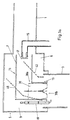
- the illustrated embodiment of the gas burner according to the invention comprises an air supply duct 1 and a tubular one Combustion chamber 3, which are connected via a deflection device. which is generally designated 5.
- the deflection device 5 contains a premixing tube 7 and one surrounding the premixing tube 7 Secondary air duct 9, the pre-mixing tube 7 and the secondary air duct 9 are substantially concentric with each other.
- the premix pipe 7 is substantially rectangular, wherein a leg 11 runs parallel to the air supply duct 1 and with the wall of the air supply duct 1, an inlet opening for the secondary air duct 9 forms.
- the other leg 13 of the premix tube 13 is parallel to the direction of gas flow in the combustion chamber 3, that is parallel to the longitudinal direction of the combustion chamber 3.
- Premix pipe 7 In the Premix pipe 7 is a feed line for fuel gas 15, which via a fuel gas nozzle 17 into the air flow in the premixing tube 7 dispense and mixed with this.
- an ignition electrode 19 At the mouth of the premix pipe 7 in the combustion chamber 3 is an ignition electrode 19 for Ignition of the escaping rich air / fuel gas mixture is provided.
- Ignition of the escaping rich air / fuel gas mixture In addition to the direct combustion of this fuel mixture takes place secondary combustion with that via the secondary air duct 9 supplied secondary air instead.
- a deflection element 30 is inserted in the leg 13, that in the parallel to the air supply duct 1 leg 11 protrudes.
- the deflection element 30 has four cross-shaped in an upper region 30a arranged flat surfaces 31 parallel to the direction of the Leg 13 on, the ends of this cross on the walls of the Leg 13 of the premixing tube rest.
- a lower area 30b the cross-shaped cross section goes into angled flat blade sections 32 over.
- These blade sections form with the corresponding surface in section 30a an obtuse angle and are arranged rotationally symmetrically in the manner of a propeller, so that they each give an angular momentum to the gas stream hitting them or give swirl in the same direction.
- the blade sections 32 do not have to be level, but can also, for example after Kind of a turbine blade, be curved.
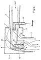
- the deflecting element 30 has a double function. Through the cruciform Part in the area 30a, which in the area of Leg 11 of the premix tube 7 protrudes, the proportion of Gas flow in the pre-mixing tube 7 is limited to the outside the combustion chamber 3 is guided. This proportion is the smaller, ever further the element 30 protrudes into the leg 11. This will compensates for the imbalance, otherwise between the flow exist on the outside and inside of the combustion chamber 3 would.
- the blade-shaped sections 32 give this in each case an angular momentum, each in the same direction, so that a vortex with an axis of rotation in essentially parallel to the flow direction in the combustion chamber 3, i.e. parallel to its longitudinal axis.
- Air guide surfaces 40 and 42 are arranged in the secondary air duct 9, which are shown in Fig. 1a and 1b with dashed lines are. These air baffles are responsible for the main part of the Air flow in the secondary air duct 9 to the mouth of the premix tube 7 to concentrate in the combustion chamber 3, so that the Secondary combustion is optimized. In contrast, the current the air in the secondary air duct 9 to the walls of the combustion chamber minimized.
- the secondary air duct in the secondary air duct additional means for generating a Twists the gas flow with an axis of rotation parallel to that Flow direction provided in the combustion chamber 3.
- swirl is opposite to the swirl caused by the blade-shaped sections 32 of the deflecting element 30 is produced. This results in a particularly good mixing of the secondary air with the emerging fuel mixture.
Landscapes
- Engineering & Computer Science (AREA)
- Chemical & Material Sciences (AREA)
- Combustion & Propulsion (AREA)
- Mechanical Engineering (AREA)
- General Engineering & Computer Science (AREA)
- Gas Burners (AREA)
- Gas Separation By Absorption (AREA)
- Glass Compositions (AREA)
- Air Supply (AREA)
- Pre-Mixing And Non-Premixing Gas Burner (AREA)
Description
- Fig. 1a
- zeigt einen schematischen Querschnitt eines erfindungsgemäßen Gasbrenners.
- Fig. 1b
- zeigt dieselbe Querschnittsansicht wie Fig. 1a, jedoch mit eingezeichneten Strömungspfeilen.
- Fig. 2a
- zeigt eine Draufsicht eines in dem erfindungsgemäßen Gasbrenner angeordneten Ablenkelements.
- Fig. 2b
- zeigt eine Vorderansicht des in Fig. 2a dargestellten Ablenkelements.
- 1
- Luftzuführkanal
- 3
- Brennkammer
- 5
- Umlenkvorrichtung
- 7
- Vormischrohr
- 9
- Sekundärluftkanal
- 11
- erster Schenkel des Vormischrohrs
- 13
- zweiter Schenkel des Vormischrohrs
- 15
- Brenngaszufuhr
- 17
- Brenngasdüse
- 19
- Zündelektrode
- 30
- Ablenkelement
- 30a
- oberer Abschnitt des Ablenkelements
- 30b
- unterer Abschnitt des Ablenkelements
- 31
- kreuzförmige Luftleitflächen des Ablenkelements
- 32
- schaufelförmiger Abschnitt des Ablenkelements
- 40, 42
- Luftleitflächen
Claims (10)
- Gasbrenner, insbesondere zur Verwendung in der Küchentechnik, mit einem Luftzuführkanal (1), einer Brenngaszufuhr (15), einer Umlenkvorrichtung (5) und einer Brennkammer (3), wobei der Luftzuführkanal (1) und die Brennkammer (3) in einem Winkel zueinander angeordnet sind, die Umlenkvorrichtung (5) zwischen dem Luftzuführkanal (1) und der Brennkammer (3) angeordnet ist,
die Umlenkvorrichtung (5) eine Vormischkammer (7) und einen Sekundärluftkanal (9) umfaßt, die Vormischkammer (7) einen ersten Abschnitt (11) parallel der Längsrichtung des Luftzuführkanals (1) und einen zweiten Abschnitt (13) parallel der Längsrichtung die Brennkammer (3) aufweist,
die Brenngaszufuhr (15) in den ersten Abschnitt (11) der Vormischkammer (7) mündet, und
eine Strömungsausgleichseinrichtung (30, 40, 42) zumindest zum Teil innerhalb der Umlenkeinrichtung (5) und stromabwärts der Mündungsöffnung der Brenngaszufuhr (15) angeordnet ist,
dadurch gekennzeichnet, daß
die Strömungsausgleichseinrichtung (30, 40, 42) zum einen ein Aufteilen des Stroms aus einer Luft-Brenngas-Mischung in zumindest zwei Teilströme durch ein Ablenkelement (30), das zumindest ein Ende (30a) quer zur Strömungsrichtung und zu dem Luftzuführkanal (1) weisend mit Leitflächen (31) parallel zur Strömungsrichtung in der Brennkammer (3), sich von dem ersten Abschnitt (11) in den zweiten Abschnitt (13) der Vormischkammer (7) erstreckend, aufweist, und zum anderen stromab davon ein Einprägen einer Impulskomponente parallel und/oder entgegengesetzt zu der Strömungsrichtung in zumindest einen Teil des Stroms aus der Luft-Brenngas-Mischung zur Vergleichmäßigung der Strömung in der Brennkammer (3), senkrecht zur Strömungsrichtung, bewirkt. - Gasbrenner nach Anspruch 1, dadurch gekennzeichnet, daß
die Strömungsausgleichseinrichtung (30, 40, 42) den Strom aus der Luft-Brenngas-Mischung vor der Strömungsumlenkung aufteilt und einen ersten, kleineren Teilstrom zu der Außenseite der Brennkammer (3) und einen zweiten, größeren Teilstrom zu der Innenseite der Brennkammer (3) führt, wobei die Außenseite der Brennkammer weiter von dem Lufzuführkanal (1) weg als die Innenseite der Brennkammer (3) angeordnet ist. - Gasbrenner nach Anspruch 1 oder 2, dadurch gekennzeichnet, daß
die Strömungsausgleichseinrichtung (30, 40, 42) nach der Strömungsumlenkung zumindest ein Prallblech (40, 42) umfaßt, das vorzugsweise zumindest teilweise spiralförmig ausgebildet ist, wobei die Spiralachse parallel zur Strömungsrichtung in der Brennkammer (3) verläuft. - Gasbrenner nach einem der vorangehenden Ansprüche, dadurch gekennzeichnet, daß
die Strömungsausgleichseinrichtung (30, 40, 42) eine Einrichtung (30b, 32) zum Erzeugen einer Rotationsverwirbelung nach der Strömungsumlenkung aufweist, wobei die Achse der so erzeugten Rotation im wesentlichen parallel zu der Richtung der Strömung in der Brennkammer (3) ist. - Gasbrenner nach einem der vorangehenden Ansprüche, dadurch gekennzeichnet, daß
die Leitflächen (31) kreuzförmig angeordnet sind. - Gasbrenner nach Anspruch 5, dadurch gekennzeichnet, daß
die kreuzförmig angeordneten Leitflächen (31) des Ablenkelements (30) an dem anderen, zu der Brennkammer (3) weisenden Ende (30b) abgewinkelt sind, so daß abgewinkelte Abschnitte (32) anstehen, die bezogen auf eine Rotation um die Längsachse des Ablenkelements (30) in die gleiche Richtung weisen. - Gasbrenner nach einem der vorangehenden Ansprüche, dadurch gekennzeichnet, daß
in der Vormischkammer (7) und/oder in dem Sekundärluftkanal (9) Mittel zur Vergleichmäßigung der Strömung in der Brennkammer (3), senkrecht zur Strömungsrichtung in der Brennkammer (3), vorgesehen sind. - Gasbrenner nach einem der vorangehenden Ansprüche, dadurch gekennzeichnet, daß
in der Vormischkammer (7) und in dem Sekundärluftkanal (9) Mittel zur Erzeugung eines Dralls der Strömung mit einer Rotationsachse parallel zu der Strömungsrichtung in der Brennkammer (3) vorgesehen sind, wobei der in der Vormischkammer (7) aufgegebene Drall entgegengesetzt zu dem Drall ist, welcher in dem Sekundärluftkanal (9) aufgegeben wird. - Gasbrenner nach Anspruch 7 oder 8, gekennzeichnet durch
eine Ablenkeinrichtung (40, 42) in dem Sekundärluftkanal (9), welche einen größeren Anteil der Sekundärluft zu dem Bereich der Mündung der Vormischkammer (7) in die Brennkammer (3), und
einen kleineren Anteil der Sekundärluft zu der Außen- beziehungsweise der Innenseite der Brennkammer (3) lenkt. - Gasbrenner nach einem der Ansprüche 7 bis 9, dadurch gekennzeichnet, daß
die Vormischkammer (7) winkelförmig ausgebildet ist und die Mittel zur Vergleichmäßigung des Gasstroms in der Brennkammer (3) in einem Bereich im wesentlichen parallel zu der Strömungsrichtung in der Brennkammer (3) angeordnet sind.
Applications Claiming Priority (2)
| Application Number | Priority Date | Filing Date | Title |
|---|---|---|---|
| DE19708218 | 1997-02-28 | ||
| DE19708218A DE19708218C2 (de) | 1997-02-28 | 1997-02-28 | Gasbrenner |
Publications (3)
| Publication Number | Publication Date |
|---|---|
| EP0863366A2 EP0863366A2 (de) | 1998-09-09 |
| EP0863366A3 EP0863366A3 (de) | 1999-07-07 |
| EP0863366B1 true EP0863366B1 (de) | 2003-02-19 |
Family
ID=7821876
Family Applications (1)
| Application Number | Title | Priority Date | Filing Date |
|---|---|---|---|
| EP97120543A Expired - Lifetime EP0863366B1 (de) | 1997-02-28 | 1997-11-24 | Gasbrenner |
Country Status (5)
| Country | Link |
|---|---|
| US (1) | US5931657A (de) |
| EP (1) | EP0863366B1 (de) |
| JP (1) | JP3657766B2 (de) |
| AT (1) | ATE232950T1 (de) |
| DE (2) | DE19708218C2 (de) |
Families Citing this family (10)
| Publication number | Priority date | Publication date | Assignee | Title |
|---|---|---|---|---|
| US6872070B2 (en) | 2001-05-10 | 2005-03-29 | Hauck Manufacturing Company | U-tube diffusion flame burner assembly having unique flame stabilization |
| SE532693C2 (sv) * | 2007-03-29 | 2010-03-16 | Wo R Ld Consulting Ab | Avvattningsanordning |
| DE102008000050A1 (de) * | 2007-08-07 | 2009-02-12 | Alstom Technology Ltd. | Brenner für eine Brennkammer einer Turbogruppe |
| KR101371100B1 (ko) * | 2013-08-12 | 2014-03-07 | (주)티에스케이에프 | 가스오븐레인지의 연소용 가스와 공기 혼합장치 |
| WO2016024005A1 (en) * | 2014-08-14 | 2016-02-18 | Munster Simms Engineering Limited | Heating apparatus |
| GB2529233B (en) * | 2014-08-14 | 2017-09-27 | Munster Simms Eng Ltd | Burner device for heating apparatus |
| DE202017100629U1 (de) * | 2017-02-07 | 2017-02-20 | Palux Aktiengesellschaft | Gasbrennervorrichtung für einen Wärmetauscher |
| US10253978B2 (en) * | 2017-03-10 | 2019-04-09 | Lennox Industries Inc. | Gas-air mixer assembly |
| CN111033123B (zh) * | 2017-06-19 | 2022-08-23 | 塞拉斯热能技术有限责任公司 | 用于改变不同腔之间的过渡流动效应的挡板组件 |
| IT202100002357A1 (it) | 2021-02-03 | 2022-08-03 | Ali Group S R L | “dispositivo antirisonanza in un forno a gas del tipo per la cottura degli alimenti nella ristorazione collettiva” |
Family Cites Families (12)
| Publication number | Priority date | Publication date | Assignee | Title |
|---|---|---|---|---|
| CH136320A (de) * | 1928-12-10 | 1929-11-15 | Hufschmidt Karl | Brenner für Kohlenstaubfeuerungen. |
| US2244821A (en) * | 1940-05-13 | 1941-06-10 | Frederick S Bloom | Combustion apparatus |
| US2615407A (en) * | 1949-06-28 | 1952-10-28 | Comb Eng Superheater Inc | Distributor means for pulverized fuel burners |
| US2610675A (en) * | 1950-11-16 | 1952-09-16 | C A Olsen Mfg Company | Flame retaining atmospheric gas burner |
| FR1232372A (fr) * | 1959-04-18 | 1960-10-07 | Gaz De France | Brûleur pour gaz à faible vitesse de déflagration |
| US3299940A (en) * | 1963-06-22 | 1967-01-24 | American Smelting Refining | Burner structure |
| GB1345442A (en) * | 1972-06-14 | 1974-01-30 | Imp Metals Ind Kynoch Ltd | Gas-fired water heating applinances |
| DE2319194A1 (de) * | 1973-04-16 | 1974-10-24 | Konstantin Sergeewitsc Pirogow | Gasbrenner |
| US3915625A (en) * | 1974-05-02 | 1975-10-28 | Raytheon Co | Heat injector gas burner |
| US3957421A (en) * | 1974-09-03 | 1976-05-18 | Raytheon Company | Heat injector gas burner |
| DE3327140A1 (de) * | 1983-07-27 | 1985-02-14 | Philipp Kreis GmbH & Co Truma-Gerätebau, 8000 München | Gasbrenner, insbesondere fuer fluessiggas, zum einbau in einen waermetauscher |
| JPH06105516A (ja) * | 1992-09-17 | 1994-04-15 | Aisin Aw Co Ltd | 電気自動車駆動装置 |
-
1997
- 1997-02-28 DE DE19708218A patent/DE19708218C2/de not_active Expired - Fee Related
- 1997-11-24 EP EP97120543A patent/EP0863366B1/de not_active Expired - Lifetime
- 1997-11-24 DE DE59709350T patent/DE59709350D1/de not_active Expired - Lifetime
- 1997-11-24 AT AT97120543T patent/ATE232950T1/de not_active IP Right Cessation
-
1998
- 1998-02-23 JP JP04009198A patent/JP3657766B2/ja not_active Expired - Fee Related
- 1998-02-25 US US09/030,376 patent/US5931657A/en not_active Expired - Lifetime
Also Published As
| Publication number | Publication date |
|---|---|
| JP3657766B2 (ja) | 2005-06-08 |
| EP0863366A2 (de) | 1998-09-09 |
| DE59709350D1 (de) | 2003-03-27 |
| JPH1137422A (ja) | 1999-02-12 |
| ATE232950T1 (de) | 2003-03-15 |
| DE19708218C2 (de) | 2002-01-31 |
| DE19708218A1 (de) | 1998-09-03 |
| EP0863366A3 (de) | 1999-07-07 |
| US5931657A (en) | 1999-08-03 |
Similar Documents
| Publication | Publication Date | Title |
|---|---|---|
| EP0619457B1 (de) | Vormischbrenner | |
| EP0675322B1 (de) | Vormischbrenner | |
| EP0623786B1 (de) | Brennkammer | |
| EP1802915B1 (de) | Brenner für gasturbine | |
| EP0548396B1 (de) | Vorrichtung für die Vermischung zweier gasförmiger Komponenten und Brenner, in welchem diese Vorrichtung eingesetzt wird | |
| DE19708218C2 (de) | Gasbrenner | |
| EP0428174B1 (de) | Drallflammen-Mischvorrichtung für Ölbrenner | |
| EP0864812A2 (de) | Mischeinrichtung für Gas- und Ölbrenner | |
| CH538093A (de) | Brennervorrichtung für ein piezo-elektrisches Gasfeuerzeug | |
| DE3801681C1 (en) | Method for burning gaseous or liquid fuel and burner for carrying out this method | |
| EP0132831A2 (de) | Gasbrenner, insbesondere für Flüssiggas, zum Einbau in einen Wärmetauscher | |
| DE19927013B4 (de) | Gebläsebrenner | |
| EP0115858A1 (de) | Brenner zum Einbau in Heizungs- und Dampferzeugungsanlagen | |
| EP0654637A1 (de) | Gasbrenner | |
| AT398344B (de) | Vormischgasbrenner | |
| DE2713759C2 (de) | Brenner für Heizöl oder Heizgas | |
| DE1007931B (de) | Brenner fuer Industrieoefen | |
| DE102017114570A1 (de) | Brennerkopf und Verbrennungsverfahren | |
| DE102004013434B4 (de) | Verfahren und Heizölbrenner zur Optimierung des Verbrennungsvorgangs | |
| DE19824719A1 (de) | Brenner, insbesondere Ölbrenner | |
| DE4329236C1 (de) | Verfahren zum Betrieb eines Ejektor-Stufenluft-Wirbelbrenners für eine Kohlenstaubfeuerung und Ejektor-Stufenluft-Wirbelbrenner | |
| AT409412B (de) | Gebläsebrenner | |
| DE19542164A1 (de) | Vormischbrenner | |
| DE544867C (de) | Gasduese fuer Bunsenbrenner | |
| DE29520696U1 (de) | Kohlenstaubbrenner |
Legal Events
| Date | Code | Title | Description |
|---|---|---|---|
| PUAI | Public reference made under article 153(3) epc to a published international application that has entered the european phase |
Free format text: ORIGINAL CODE: 0009012 |
|
| AK | Designated contracting states |
Kind code of ref document: A2 Designated state(s): AT BE CH DE DK ES FI FR GB GR IE IT LI LU MC NL PT SE |
|
| AX | Request for extension of the european patent |
Free format text: AL;LT;LV;MK;RO;SI |
|
| PUAL | Search report despatched |
Free format text: ORIGINAL CODE: 0009013 |
|
| AK | Designated contracting states |
Kind code of ref document: A3 Designated state(s): AT BE CH DE DK ES FI FR GB GR IE IT LI LU MC NL PT SE |
|
| AX | Request for extension of the european patent |
Free format text: AL;LT;LV;MK;RO;SI |
|
| 17P | Request for examination filed |
Effective date: 19990804 |
|
| AKX | Designation fees paid |
Free format text: AT BE CH DE DK ES FI FR GB GR IE IT LI LU MC NL PT SE |
|
| RAP1 | Party data changed (applicant data changed or rights of an application transferred) |
Owner name: RATIONAL AG |
|
| 17Q | First examination report despatched |
Effective date: 20010504 |
|
| GRAG | Despatch of communication of intention to grant |
Free format text: ORIGINAL CODE: EPIDOS AGRA |
|
| GRAG | Despatch of communication of intention to grant |
Free format text: ORIGINAL CODE: EPIDOS AGRA |
|
| GRAH | Despatch of communication of intention to grant a patent |
Free format text: ORIGINAL CODE: EPIDOS IGRA |
|
| GRAH | Despatch of communication of intention to grant a patent |
Free format text: ORIGINAL CODE: EPIDOS IGRA |
|
| GRAA | (expected) grant |
Free format text: ORIGINAL CODE: 0009210 |
|
| AK | Designated contracting states |
Designated state(s): AT BE CH DE DK ES FI FR GB GR IE IT LI LU MC NL PT SE |
|
| PG25 | Lapsed in a contracting state [announced via postgrant information from national office to epo] |
Ref country code: NL Free format text: LAPSE BECAUSE OF FAILURE TO SUBMIT A TRANSLATION OF THE DESCRIPTION OR TO PAY THE FEE WITHIN THE PRESCRIBED TIME-LIMIT Effective date: 20030219 Ref country code: IE Free format text: LAPSE BECAUSE OF FAILURE TO SUBMIT A TRANSLATION OF THE DESCRIPTION OR TO PAY THE FEE WITHIN THE PRESCRIBED TIME-LIMIT Effective date: 20030219 Ref country code: GR Free format text: LAPSE BECAUSE OF FAILURE TO SUBMIT A TRANSLATION OF THE DESCRIPTION OR TO PAY THE FEE WITHIN THE PRESCRIBED TIME-LIMIT Effective date: 20030219 Ref country code: FI Free format text: LAPSE BECAUSE OF FAILURE TO SUBMIT A TRANSLATION OF THE DESCRIPTION OR TO PAY THE FEE WITHIN THE PRESCRIBED TIME-LIMIT Effective date: 20030219 |
|
| REG | Reference to a national code |
Ref country code: GB Ref legal event code: FG4D Free format text: NOT ENGLISH |
|
| REG | Reference to a national code |
Ref country code: CH Ref legal event code: EP |
|
| GBT | Gb: translation of ep patent filed (gb section 77(6)(a)/1977) |
Effective date: 20030219 |
|
| REG | Reference to a national code |
Ref country code: IE Ref legal event code: FG4D Free format text: GERMAN |
|
| REF | Corresponds to: |
Ref document number: 59709350 Country of ref document: DE Date of ref document: 20030327 Kind code of ref document: P |
|
| PG25 | Lapsed in a contracting state [announced via postgrant information from national office to epo] |
Ref country code: SE Free format text: LAPSE BECAUSE OF FAILURE TO SUBMIT A TRANSLATION OF THE DESCRIPTION OR TO PAY THE FEE WITHIN THE PRESCRIBED TIME-LIMIT Effective date: 20030519 Ref country code: PT Free format text: LAPSE BECAUSE OF FAILURE TO SUBMIT A TRANSLATION OF THE DESCRIPTION OR TO PAY THE FEE WITHIN THE PRESCRIBED TIME-LIMIT Effective date: 20030519 Ref country code: DK Free format text: LAPSE BECAUSE OF FAILURE TO SUBMIT A TRANSLATION OF THE DESCRIPTION OR TO PAY THE FEE WITHIN THE PRESCRIBED TIME-LIMIT Effective date: 20030519 |
|
| ET | Fr: translation filed | ||
| NLV1 | Nl: lapsed or annulled due to failure to fulfill the requirements of art. 29p and 29m of the patents act | ||
| PG25 | Lapsed in a contracting state [announced via postgrant information from national office to epo] |
Ref country code: ES Free format text: LAPSE BECAUSE OF FAILURE TO SUBMIT A TRANSLATION OF THE DESCRIPTION OR TO PAY THE FEE WITHIN THE PRESCRIBED TIME-LIMIT Effective date: 20030828 |
|
| REG | Reference to a national code |
Ref country code: IE Ref legal event code: FD4D Ref document number: 0863366E Country of ref document: IE |
|
| PG25 | Lapsed in a contracting state [announced via postgrant information from national office to epo] |
Ref country code: LU Free format text: LAPSE BECAUSE OF NON-PAYMENT OF DUE FEES Effective date: 20031124 Ref country code: AT Free format text: LAPSE BECAUSE OF NON-PAYMENT OF DUE FEES Effective date: 20031124 |
|
| PG25 | Lapsed in a contracting state [announced via postgrant information from national office to epo] |
Ref country code: MC Free format text: LAPSE BECAUSE OF NON-PAYMENT OF DUE FEES Effective date: 20031130 Ref country code: LI Free format text: LAPSE BECAUSE OF NON-PAYMENT OF DUE FEES Effective date: 20031130 Ref country code: CH Free format text: LAPSE BECAUSE OF NON-PAYMENT OF DUE FEES Effective date: 20031130 Ref country code: BE Free format text: LAPSE BECAUSE OF NON-PAYMENT OF DUE FEES Effective date: 20031130 |
|
| PLBE | No opposition filed within time limit |
Free format text: ORIGINAL CODE: 0009261 |
|
| STAA | Information on the status of an ep patent application or granted ep patent |
Free format text: STATUS: NO OPPOSITION FILED WITHIN TIME LIMIT |
|
| 26N | No opposition filed |
Effective date: 20031120 |
|
| BERE | Be: lapsed |
Owner name: *RATIONAL A.G. Effective date: 20031130 |
|
| REG | Reference to a national code |
Ref country code: CH Ref legal event code: PL |
|
| PGFP | Annual fee paid to national office [announced via postgrant information from national office to epo] |
Ref country code: GB Payment date: 20051123 Year of fee payment: 9 |
|
| GBPC | Gb: european patent ceased through non-payment of renewal fee |
Effective date: 20061124 |
|
| PG25 | Lapsed in a contracting state [announced via postgrant information from national office to epo] |
Ref country code: GB Free format text: LAPSE BECAUSE OF NON-PAYMENT OF DUE FEES Effective date: 20061124 |
|
| PGFP | Annual fee paid to national office [announced via postgrant information from national office to epo] |
Ref country code: FR Payment date: 20100331 Year of fee payment: 13 |
|
| REG | Reference to a national code |
Ref country code: FR Ref legal event code: ST Effective date: 20110801 |
|
| PG25 | Lapsed in a contracting state [announced via postgrant information from national office to epo] |
Ref country code: FR Free format text: LAPSE BECAUSE OF NON-PAYMENT OF DUE FEES Effective date: 20101130 |
|
| REG | Reference to a national code |
Ref country code: DE Ref legal event code: R084 Ref document number: 59709350 Country of ref document: DE |
|
| REG | Reference to a national code |
Ref country code: DE Ref legal event code: R084 Ref document number: 59709350 Country of ref document: DE Effective date: 20140725 |
|
| PGFP | Annual fee paid to national office [announced via postgrant information from national office to epo] |
Ref country code: DE Payment date: 20141120 Year of fee payment: 18 |
|
| PGFP | Annual fee paid to national office [announced via postgrant information from national office to epo] |
Ref country code: IT Payment date: 20141121 Year of fee payment: 18 |
|
| REG | Reference to a national code |
Ref country code: DE Ref legal event code: R119 Ref document number: 59709350 Country of ref document: DE |
|
| PG25 | Lapsed in a contracting state [announced via postgrant information from national office to epo] |
Ref country code: IT Free format text: LAPSE BECAUSE OF NON-PAYMENT OF DUE FEES Effective date: 20151124 |
|
| PG25 | Lapsed in a contracting state [announced via postgrant information from national office to epo] |
Ref country code: DE Free format text: LAPSE BECAUSE OF NON-PAYMENT OF DUE FEES Effective date: 20160601 |