EP0862837B1 - Procédé et dispositif pour multiplexage statistique de programmes utilisant le niveau de remplissage d'un tampon de décodeur - Google Patents
Procédé et dispositif pour multiplexage statistique de programmes utilisant le niveau de remplissage d'un tampon de décodeur Download PDFInfo
- Publication number
- EP0862837B1 EP0862837B1 EP96940351A EP96940351A EP0862837B1 EP 0862837 B1 EP0862837 B1 EP 0862837B1 EP 96940351 A EP96940351 A EP 96940351A EP 96940351 A EP96940351 A EP 96940351A EP 0862837 B1 EP0862837 B1 EP 0862837B1
- Authority
- EP
- European Patent Office
- Prior art keywords
- buffer
- packet
- decoder
- channel
- decoder buffer
- Prior art date
- Legal status (The legal status is an assumption and is not a legal conclusion. Google has not performed a legal analysis and makes no representation as to the accuracy of the status listed.)
- Expired - Lifetime
Links
Images


Classifications
-
- H—ELECTRICITY
- H04—ELECTRIC COMMUNICATION TECHNIQUE
- H04N—PICTORIAL COMMUNICATION, e.g. TELEVISION
- H04N21/00—Selective content distribution, e.g. interactive television or video on demand [VOD]
- H04N21/40—Client devices specifically adapted for the reception of or interaction with content, e.g. set-top-box [STB]; Operations thereof
- H04N21/43—Processing of content or additional data, e.g. demultiplexing additional data from a digital video stream; Elementary client operations, e.g. monitoring of home network or synchronising decoder's clock; Client middleware
- H04N21/434—Disassembling of a multiplex stream, e.g. demultiplexing audio and video streams, extraction of additional data from a video stream; Remultiplexing of multiplex streams; Extraction or processing of SI; Disassembling of packetised elementary stream
- H04N21/4347—Demultiplexing of several video streams
-
- H—ELECTRICITY
- H04—ELECTRIC COMMUNICATION TECHNIQUE
- H04N—PICTORIAL COMMUNICATION, e.g. TELEVISION
- H04N21/00—Selective content distribution, e.g. interactive television or video on demand [VOD]
- H04N21/20—Servers specifically adapted for the distribution of content, e.g. VOD servers; Operations thereof
- H04N21/23—Processing of content or additional data; Elementary server operations; Server middleware
- H04N21/236—Assembling of a multiplex stream, e.g. transport stream, by combining a video stream with other content or additional data, e.g. inserting a URL [Uniform Resource Locator] into a video stream, multiplexing software data into a video stream; Remultiplexing of multiplex streams; Insertion of stuffing bits into the multiplex stream, e.g. to obtain a constant bit-rate; Assembling of a packetised elementary stream
- H04N21/2365—Multiplexing of several video streams
-
- H—ELECTRICITY
- H04—ELECTRIC COMMUNICATION TECHNIQUE
- H04N—PICTORIAL COMMUNICATION, e.g. TELEVISION
- H04N7/00—Television systems
- H04N7/16—Analogue secrecy systems; Analogue subscription systems
- H04N7/173—Analogue secrecy systems; Analogue subscription systems with two-way working, e.g. subscriber sending a programme selection signal
- H04N7/17309—Transmission or handling of upstream communications
- H04N7/17336—Handling of requests in head-ends
Definitions
- the field of the present invention is video compression.
- the present invention relates to the encoding, formatting, and distribution of compressed video programs. It is particularly, but not necessarily, applicable to a particular video compression technique known as variable bit-rate(VBR) encoding.
- VBR encoding can be used to overcome the well-known problem of most video compression encoders where the image quality tends to vary as a function of image complexity.
- a video program will contain a variety of scenes. Many of these scenes are lacking in motion or detail and are therefore easily compressed, while many other scenes contain complex details which are generally more difficult to compress, particularly when moving in a complex or random manner. Therefore, unless the available bandwidth is very high, the perceived quality of the decompressed and reconstructed images will tend to vary from one scene to the next. This problem becomes more serious as the available bandwidth is reduced until, eventually, the video quality becomes unacceptable, often because of just a few problem scenes.
- VBR encoding overcomes this problem by allocating more bits to those scenes which are difficult to compress and fewer bits to those scenes which are more easily compressed. In this way, the decompressed and reconstructed images can be made to appear consistently uniform, and therefore superior to the reconstructed images derived from the constant bit-rate encoder adjusted for the same average rate of compression. As a result, it is possible to compress a video program more efficiently when using the VBR encoding technique. This not only increases the number and variety of programs or program streams that can be delivered over a fixed-bandwidth communication channel, but also reduces the storage capacity requirements at the head end or other site where the program library is maintained.
- VBR encoding technique presents certain problems when manipulating or editing the compressed bit-streams.
- the possibility of exceeding the capacity of the channel is not only a problem with VBR-encoded data, this is also a problem with non VBR-encoded data.
- the present invention is applicable also to non VBR-encode data.
- One known technique that is used to alleviate this problem is to buffer the compressed bit-stream at the transmission end of the communication channel in order to convert the variable rate stream to a constant rate stream. In such a case, it is also necessary to buffer the signal received at the other end of the channel in order to recover the variable rate stream that is necessary for proper timing of the reconstructed video images.
- the required amount of buffering would be prohibitively expensive and would introduce long delays into the distribution system.
- existing video compression standards such as the MPEG standards, a set of International Organization for Standardization/International Electrotechnical Commission (ISO/IEC) standards, specify limits on the amount of buffering required for conforming decoders. Therefore, it is important that the received bit-streams be decodable without exceeding these limits.
- Another prior art technique that can be used to reduce the inefficiency of transmitting VBR encoded (and non-VBR encoded) programs over a fixed-bandwidth channel combines a plurality of program streams into a single multiplex. Although each additional program stream will increase the overall data rate of the multiplex, the variance of the average per-stream data rate of this multiplex will tend to decrease in approximate proportion to the number of program streams, assuming approximate statistical independence of them. Therefore, if the nominal rate that can be accommodated by the channel is significantly greater than the average rate of a single program stream, then the channel utilization can be significantly improved. This technique is known in the art as statistical multiplexing.
- one prior art method of assuring that buffer overflow does not occur is to add feedback between the encoder buffer and the encoder.
- a buffer fullness signal from the buffer informs the encoder to reduce the bit-rate so that the buffer does not overflow.
- the feedback signal from the buffer to the encoder, enables the encoder to increase the bit-rate in order to maintain image quality.
- Such feedback is particularly effective when combined with statistical multiplexing.
- a single encoder buffer may be at the output of the multiplexer, and feedback from that buffer is to all the encoders of the programs being multiplexed. Because the multiplexing reduces effective per-stream data rate variance, in general, less buffering would be required to convert the multiplex to a fixed bit-rate stream than if each individual encoder included a VBR-to-constant bit-rate buffer.
- encoder buffering with statistical multiplexing with feedback for conveying encoded, particularly VBR encoded program streams over fixed-bandwidth channels can be effective, but generally may not be sufficient when efficient utilization of the entire channel is important.
- one of the factors that limits the efficiency of transmitting the multiplex is the finite overall memory available for buffering at the decoder/demultiplexer. While statistical multiplexing usually provides sufficient benefit due to the small probability that all program streams will have complex scenes at the same time, there is still a finite chance of such peaks occurring. If the peaks are such that no more buffer space is available at the decoder, fill packets are sent, there is a delay, and the channel utilization (channel efficiency) goes down.
- Haskell discloses a method and apparatus to address the problem of buffer overflow and underflow. Haskell also mentions in one embodiment the alleviation of overflow by multiplexing packets from other streams before a stream whose decoder buffer is in danger of overflow, but does not specify any details of such a technique.
- RIEMANN "Der MPEG-2 Standard (Teil 5_2)" FERNSEH UND KINOTECHNIK, vol. 48, no. 10, October 1994 (1994-10), pages 545-553, XP000468290 HEIDELBERG, DE discloses the use of Decoding Time Stamps (DTS) for decoder buffer control.
- DTS Decoding Time Stamps
- Document EP 705 042 (Article 54(3) document) discloses a method of multiplexing streams of audio-visual signals coded according to standard MPEG1.
- An object of the present invention is to provide techniques for efficiently delivering several compressed video programs over a communications channel.
- Another object of the present invention is to provide techniques for multiplexing several encoded video programs, applicable to both real time encoding and remote encoding situations.
- Another object of the invention is to provide techniques reducing the chance that a buffer overflow condition occurs at the decoder.
- Another object of the invention is to provide techniques for reducing the chance that a buffer underflow condition occurs at the decoder.
- Another object of the invention is to provide techniques channel efficiency by not sending fill packets of stuffing bits when possible.
- the above and other objects of the invention are provided for in a multiplexing method according to claim 1, an apparatus according to claim 14 and a server according to claim 19 which achieve high data channel utilization by determining the order of sending data packets of program streams into the data channel.
- the method determines which packet to send next by selecting a next channel that has a decoder buffer that is not approaching a full state.
- the method further includes selecting a channel that substantially balances the decoder buffers of the decoders with which the program streams are decodeable.
- balancing the decoder buffers includes keeping approximately the same time duration stored in each decoder buffer.
- the preferred embodiment of the invention utilizes the presently known technique of variable bit-rate ("VBR") encoding and decoding of video data, including soundtrack or audio data, and uses a compression method to reduce the total amount of data required to represent a video stream.
- VBR variable bit-rate
- the present invention is applicable also to non-VBR encoded data, as would be clear to one in the art.
- the preferred embodiment uses the MPEG coding standard, the invention is applicable to many other coding methods, as also would be apparent to one in the art.
- the invention deals with complete coded streams, including both video and audio.
- the preferred embodiment deals with MPEG streams of a single program. That is, MPEG encoded video, audio, and other data combined together as the MPEG stream of a single program.
- MPEG stream is defined herein as a program stream.
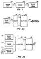
- Program source 101 such as a video tape recorder (VTR) or other program source, is used to supply uncompressed video 103 to an encoder 105.
- Encoder 105 receives uncompressed video 103 and applies a video compression process.
- the video compression is that specified by the MPEG-2 standard.
- the video compression technique provides for a VBR mode that can be used to produce video streams that can be decoded to obtain images of substantially uniformly consistent quality. Many compression methods and standards, including MPEG, have such a VBR mode.
- the compressed output 107 of encoder 105 would be written to a digital storage medium (DSM) such as a disk or tape storage media 109 for playback at a later time, or transmitted directly to a data channel for broadcast or other transfer. That is, in the nomenclature of the MPEG standard, 109 is a DSM or channel.
- DSM digital storage medium
- multiple compressed program streams are combined into a single multiplex as shown in Figures 2(a) and 2(b) .
- the multiplexer 201 combines each of the program streams 203 retrieved from storage 109 or obtained from any other source, such as an encoder 209 and/or satellite receiver 211, into a single multiplex 205 that can either be broadcast immediately over the distribution system or returned to storage for broadcasting at a later time.
- One advantage of using the multiplexing process and apparatus, also called the combining process and apparatus is to reduce the statistical variance in the video as compared to that of the individual VBR program streams 203.
- the multiplexing method has the advantage of providing the viewer with a choice of retrieving or viewing any of the program streams contained in multiplex 205.
- the multiplexing in the preferred embodiment is for a plurality of compressed program streams or for the case of transmitting several segments of a single data steam, such as a VBR or otherwise compressed program.
- a single data steam such as a VBR or otherwise compressed program.
- some or all of program streams 203 combined by the multiplexer 201 could correspond to different segments of the same video program.
- Video-On-Demand Invention One application of Our Video-On-Demand Invention is video-on-demand, where the user may choose to begin watching a program during any of a wide range of time intervals.
- multiplexer 201 is not the multiplexing of packets of elementary streams into packs of an MPEG stream as described in the context of the MPEG standard in the Appendix, in Section D entitled "Audio/Video Synchronization and MPEG Receivers.” It similarly should also be noted that in the case of using MPEG, a program stream in the context of this invention would usually be a complete pack-level MPEG stream.
- compressed program 107 is first split into a number, n, of segments 303 where each segment 305 corresponds to a fixed time interval 307 of length T seconds.
- T the time interval 307
- the compression ratio is allowed to vary over time, and different segments may contain differing amounts of compressed data.
- each of the n different segments 303 becomes an independent program stream, and each of these n independent program streams subsequently are aligned to start at the same time, herein referred to as "stacking up.”
- the stacked-up program streams 203 are multiplexed together using multiplexer 201.
- each of the program streams 203 is partitioned into variable-size packets where each packet contains the compressed data corresponding to a fixed number of pixels. Recalling that each of the program streams 203 is of the same duration and hence represents the same number of pixels, it follows that each of the program streams 203 will contain the same number of packets after partitioning. Hence, a fixed interleaving scheme may be used when multiplexing the packets from each of the n segments.
- each of the program streams 203 is partitioned into fixed-size packets and the number of packets in each stream is allowed to vary.
- Multiplexer 201 orders the packets according to the sequence in which they are to be decoded at the respective decoder.
- the last packet of each stream in set 203 may be padded or truncated.
- the second above-mentioned scheme is used. That is, the original compressed program 107 is first partitioned into fixed-length packets, and, in the segmented stream case, is then split into segments by splitter 207.
- the advantage of this order is that the splitting of the program into segments by splitter 207 can be forced to occur at packet boundaries rather than at pixel boundaries.
- the multiplexing method of the present invention assumes that all receivers that are "tuned" to a particular program stream use the same hypothetical decoder. Each such decoder has a single buffer used to receive data from a single selected stream. Thus, whenever sending data from a particular program stream, the multiplexing method effectively assumes the data will be sent along a particular communications channel including the tuned hypothetical decoder. The method of the present invention uses this assumption, for example, to estimate the fullness of the buffer of the hypothetical decoder corresponding to any stream to which the receiver containing the decoder is tuned.
- the word "receiver” as used herein means a receiving device which includes a decoder. The assumption about such hypothetical decoders does not necessarily restrict the type of decoders or receivers with which the method of the present invention works. Rather, the assumption is used by the multiplexer to make certain decisions.
- One aim of the method of the present invention is to maximize channel efficiency by avoiding, whenever possible, the sending of fill packets of stuffing bits, while at the same time minimizing the chance that one decoder buffer will become full before the others. Avoiding fill packets increases efficiency since stuffing bits are ignored at the receiver. The method also minimizes errors by avoiding, whenever possible, an underflow of any of the decoder buffers.
- Each of the program streams 203 is assumed to have been subdivided into packets prior to multiplexing.
- the multiplexer selects the next packet by using a criterion that includes whether or not any of the decoder buffers corresponding to the n different channels is about to reach a full state. The selection of the next packet determines, if none of these buffers is about to reach a full state, which of the decoder buffers corresponding to the n different channels will become empty first.
- Sending the next packet to such a buffer keeps the decoder buffers balanced.
- the complexity of the determining step depends on how complete a model of decoders is maintained at the multiplexer. The more complete the model, the less computation is involved in determining which channel to send to.
- the multiplexer in one embodiment of the present invention maintains a record of the current level of fullness of the decoder buffers corresponding to each of the n streams being transmitted. All receivers tuned to the same channel or stream are assumed to maintain identical levels of buffer fullness, and n decoder buffers or buffer fullness levels are maintained or estimated at the multiplexer.
- the channel corresponding to the decoder buffer which will be the first to become empty is determined by maintaining a record of the number of blocks in each buffer and then determining the one with the least number of blocks, where a block is a grouping of data corresponding to a fixed time duration of presentation. The size of a block can be selected to correspond to any time duration without deviating from the scope of this invention.
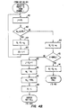
- the method starts at step 401.
- the method determines if all decoder buffers are full or approaching a full state. Normally, this is not the case and the method proceeds to select, at step 405, the next channel from which to send the next packet.
- the channel with the fewest number of blocks in its decoder buffer is selected. This channel corresponds to the channel whose decoder buffer would empty first.
- the method checks, in step 407, if the corresponding decoder buffer is approaching a full state. If it is full or approaching a full state, another channel is selected at step 411.
- the channel whose decoder buffer has the next fewest number of blocks in it is selected in step 411.
- the method checks again, in step 407, if the corresponding decoder buffer is approaching a full state. This loop of steps 407 and 411 is continued until a channel is selected that is not full or approaching a full state.
- the method sends the next packet for the selected channel. That is, the method appends the next packet to the end of the multiplex.
- a selected decoder buffer may indeed be found in step 407 to be too full to accept its next available packet to be sent, even though, according to the method of the present invention, each of the decoder buffers will generally be balanced in the sense that each buffer holds approximately the same amount of data when measured in units of time.
- the reason for this potential overflow might be that the actual quantity of data (vs. units of time) in each buffer may vary depending on the relative complexities of the different underling video streams at that point in time; that is, the quantity of data in the buffers may vary depending on the levels of compression of the corresponding streams at that point in time.
- the channel with the least units of time in its buffer may reach a full state while the other buffers are still relatively empty.
- the method of the present invention avoids sending a packet to any buffer that is too full to accept its next available packet to be sent.
- step 403 it is possible at step 403 that all decoder buffers will be found to be full. In such a case, the method will send an alternate packet.
- the alternate packet is a fill packet of stuffing bits. As has been stated, fill packets are ignored by the receiver.
- step 403 is not carried out explicitly at the beginning. Rather, if after continued repetition of steps 407 and 411, no channel with a decoder buffer that is not approaching a full state is found, an alternate packet, such as a fill packet, is selected as the next packet to send in step 409.
- an alternate packet such as a fill packet
- the determination at step 405 of the decoder buffer that will empty first is done by looking at decoding time stamps of the packets of data in the decoder buffers.
- a decoding time stamp (DTS) is data that may be present in a packet header, indicating the time that the first unit in the packet is to be decoded, where a unit is an audio frame or video picture.
- the system clock reference (SCR) is a time stamp in a pack header that defines when a particular byte is to enter the decoder, and thus can be used to set the reference clock of a decoder from time to time.
- the decoder buffer that will be first to empty is the one with the minimum difference between the values of DTS for the last ( i.e ., most recent) packet in the decoder buffer and the current value of the reference clock of the decoder model. This minimum difference exists for data in the decoder buffer, containing the least amount of time, hence the least number of blocks.
- the decoder buffer that will be the first to empty is the one with the minimum difference between the values of DTS for the last ( i.e ., most recent) packet in the decoder buffer and the first ( i.e ., oldest) packet in that decoder buffer.
- the method shown in the flow chart of Figure 4(b) determines, at step 407 of Figure 4(a) , whether the corresponding decoder buffer is too full.
- the determining method starts either after step 405 or after step 411 of Figure 4(a) , in which a particular channel is selected.
- a temporary index, j is set to the index of the first (i.e., oldest) packet in the decoder buffer for the selected channel i , that index denoted by J0 i .
- Step 423 the decoding time stamp for the packet corresponding to the index j is compared to either SCR i , the system clock reference (SCR) for the next packet to be transmitted for that channel, or, if the SCR does not exist at that point, to the reference clock of the decoder model.
- Step 423 thus determines if the packet in the buffer, based on the DTS, has already been removed, in which case (1) in step 425, B i , the current buffer fullness estimate, is reduced by n ij , the size of the oldest packet, (2) in step 427, J0 i , the index corresponding to the first (oldest) packet is incremented, and (3) the procedure loops back to the beginning step 421.
- the effect of sending the next packet is determined, in step 429, by adding m i , the size of the next packet, to B i , the current buffer fullness estimate, and the resulting B i is compared, in step 431, to BMAX i , the maximum allowed decoder buffer size for the selected channel i.
- the temporary index j is set to be one more than Jl i , the index corresponding to the last (most recent) packet in the decoder buffer for selected channel i ; (2) n ij , the size of the packet corresponding to index j , is set to m i , the size of the next packet; (3) ts ij , the decoding time stamp for the packet corresponding to the index j , is set to be DTS i , the DTS for the next packet from channel i ; Jl i , the index corresponding to the last (most recent) packet in the decoder buffer for selected channel i , is reset to index j, and the method proceeds to step 409 of Figure 4(a) , at which a packet is transmitted for the selected channel i.
- step 431 If at step 431, it is determined that the buffer fullness is greater than the maximum allowed, then at step 441. B i , the current estimate of buffer fullness is decremented by m i , the size of the next packet, and the method proceeds to step 411 of the flow chart of Figure 4(a) in which another channel is selected.
- the steps of incrementing J0 i and J1 i may be carried out modulo K , where K is some sufficiently large constant.
- a method has been disclosed that can be used to multiplex and send encoded video across channels, including fixed-bandwidth channels, while preserving the full quality of the pre-compressed signal.
- On-line storage for compressed programs is provided by individual server modules 503.
- each server module may have a hard disk large enough to contain one program that has been compressed using VBR (or other) encoding techniques.
- Additional off-line storage may be provided by an archive library 505 which may consist of one or more magnetic tape drives and a library of magnetic tapes. The programs stored in this library could also exist in the same compressed format.
- New program material can be included into the system either by adding a new tape to the archive library or by using a program source 507 such as a Video Tape Recorder (VTR) to supply uncompressed video to an encoder 511.
- VTR Video Tape Recorder
- a controller 509 is used to manage the operation of the system.
- the controller is a computer.
- Controller 509 serves as an interface to the operator when entering or modifying programming schedules, controls the transfer of programs between the archive library 505 or encoder 511 and the server modules 503, analyzes programs or maintains files describing the characteristics of each program, and determines how the multiplexes should be formed according to the present invention.
- the controller instructs an individual MUX module 513 to accept compressed program data from one or more selected server modules 503.
- Each MUX module 513 inserts fill data when the output data rate falls below the capacity of the channel. If properly instructed by the host, the MUX module 513 will also introduce pauses, insert messages, or other program material supplied by one of the other server modules 503, according to the present invention.
- a video program typically is organized as an ordered sequence of frames, each frame a scene at a particular point in time.
- frame is also used in the art of audio-compression and in the MPEG standard to refer to a basic unit of compressed audio.
- picture is also used herein to indicate a video frame.
- Each video frame may be thought of as discretized into a two-dimensional array of picture elements (called pixels or pels), and may be split into two or more fields, each field consisting of a subset of the pixels in the picture. Such splitting is called interlacing.
- NTSC U.S.A and Japan
- PAL and SECAM elsewhere
- Each pixel contains information on how to reproduce the color (hue and saturation) and brightness, and this data may be expressed in various ways.
- One way is as red, green, and blue (“RGB") values corresponding to the relative amounts of red, green, and blue primaries needed to reproduce the color and brightness.
- RGB red, green, and blue
- Cathode ray tubes common in television displays have guns that produce red, green, and blue on the screen in response to voltages in the guns.
- the data can also be expresses at each pixel as intensity data (e.g ., luminance) and color data, where the color data is expressed in chrominance coordinates, in hue and saturation coordinates, or some other way. Techniques are known for converting between the various ways of representing pixel information.
- each pixel can be represented digitally.
- a video program can be converted into a digital data stream which consists of an ordered sequence of bits describing the pixel values in each video frame.
- audio associated with the program can be convened into digital data, and can be identified with the video on a picture-by-picture basis.
- the number of bits required to represent each individual pixel may be reduced on a pixel-by-pixel basis. That is, the data of each pixel is processed (reduced) without reference to the data of any other pixel.
- the number of bits required to represent a field or a picture can be reduced by taking advantage of spatial redundancies in the field or picture. For example, regions of uniform, slowly, or smoothly varying color or brightness may be represented by fewer bits (i.e. less data) than regions of many changes and edges.
- the number of bits required to represent a sequence of pictures may be reduced by taking advantage of temporal redundancies—areas in the pictures of a sequence that vary slowly or hardly at all in time.
- image compression also is called image coding.
- the first method above commonly is called color quantization
- the second is called intraframe coding or intra-coding and typically includes color quantization
- the third is called interframe coding or inter-coding and typically, but not necessarily, includes intra-coding.
- the preferred embodiment of the present invention is for video streams which have been compressed in accordance with the MPEG standard. As will be understood to one in the art, the present invention may also be used with video streams that have been compressed using other compression schemes.
- the video part of the MPEG standard uses motion compensated predictive coding, the discrete cosine transform (DCT) and adaptive quantization, each of these operating on images on a block-by-block basis.
- Motion estimation refers to the process of computing the spatial displacement (in the form of motion vectors) from picture to picture, and is usually done by measuring the motion of blocks of pixels from picture to picture.
- Motion compensation uses the resultant motion vectors to compensate for the motion.
- MPEG uses both forward motion estimation (in which the estimation is of the future referenced to the past), and backward motion estimation (in which the estimation is of the past referenced to the future). Forward and backward motion estimation are also combined to produce bidirectional motion estimation.
- Video frames to be compressed typically consist of an array of luminance pixels, where luminance is denoted by Y , and two arrays of chrominance pixels, where the chrominance signals are denoted by C r and C b , respectively.
- video frames are classified into one of three types: I-frames, also called I-pictures and intraframe coded pictures; P-frames or P-picrures, also called predictively coded pictures; and B-frames or B-pictures, also called Bidirectionally coded pictures.
- I-frames also called I-pictures and intraframe coded pictures
- P-frames or P-picrures also called predictively coded pictures
- B-frames or B-pictures also called Bidirectionally coded pictures.
- the three types of video frames differ in their use of motion estimation.
- I-pictures use purely spatial compression and are processed independently of other pictures. Thus, I-pictures are processed entirely by intraframe operations and only a moderate level of compression is achieved. On the other hand, a complete picture can be generated from an I-picture alone.
- P-pictures and B-picrures also use predictive coding, so can be thought of as dependent pictures.
- P-pictures are coded using previous I-pictures or previous P-pictures.
- the compression of P-pictures relies on temporal prediction from previous I- or P-pictures using motion compensation. Only forward motion estimation/compensation is used in the temporal prediction.
- the I- or P-picture from which a P-picture is temporally predicted is called the anchor picture to the P-picture. It is also called the reference picture or reference frame.
- B-pictures are coded by a bidirectional motion compensated predictive encoder using the next "future" I- or P-picture for backwards prediction and the previous I- or P-picture for forward prediction.
- the two adjacent I- or P-pictures from which a B-picture is temporally predicted are thus called anchor pictures of the B-picture.
- the B-picture temporal prediction uses motion compensation in forward and/or backward directions. B-pictures are never used to predict other pictures. Due to the dependence of B-pictures on the two adjacent anchor pictures, B-pictures alone do not contain sufficient data from which to generate a recognizable picture.
- pictures are arranged in ordered groups.
- the standard allows the encoder to choose the frequency and location of I-pictures.
- a group of pictures is intended to assist random access into the sequence, thus the first coded picture in a group is normally an I-picture.
- a typical group then is a series of pictures which might include, as an example, an I-picture as the first picture, P-pictures distributed following every third picture, and a B-picture between every "I and P" and "P and P" sequence.
- a typical display order of picture types consistent with this example might include an I-picture every fifteenth frame, each I-picture followed by two B-picrures, then a sequence of a P-picture followed by two B-pictures, until the next group starts with an I-picture. That is, the display order of I B B P B B P B B P B B P B B P B B I B B P B B P B B ...
- a thirty picture-per-second environment which includes an I-picture every fifteenth frame, corresponds to having an independent picture every one half-second.
- a macroblock is the unit of motion compensation and adaptive quantization.
- a number of macroblocks comprise a picture.
- Each macroblock defines a predetermined spatial region in a picture, and contains luminance and chrominance information.
- the MPEG proposal provides for the arrangement of macroblocks into slices.
- a slice is an integer number of consecutive macroblocks from a raster of macroblocks.
- a slice represents the boundary within which differential coding of macroblock parameters, e.g ., DC coefficients of a DCT, and motion vectors, is performed.
- Each slice has its own header information, can be independent of other slices, and each contains at least one macroblock. Slices do not overlap. The position of slices may change from picture to picture. The first slice starts with the first macroblock in the picture and the last slice ends with the last macroblock in the picture.
- the first macroblock in a slice has its macroblock parameters, e.g ., DC coefficients of a DCT (if intraframe coded) and motion vectors, differentially coded from a constant value.
- Each subsequent macroblock in a slice has its macroblock parameters measured as an offset from the previous macroblock in the slice. Accordingly, the size of the slice is the minimum size for which a piece of data can be recovered and correctly decoded. If part of a slice is lost, it may not be possible to decode the differences in motion vectors or the DC coefficients contained in the remaining part of the slice.
- a macroblock comprises four 8 x 8 luminance blocks ( Y 0 , Y 1 , Y 2 , Y 3 ) and two 8 x 8 color difference blocks (C r and C b ).
- the four luminance blocks (Y 0 , Y 1 , Y 2 , Y 3 ) and two color difference blocks (C r ,C b ), which form a single macroblock, are used to encode a 16 x 16 picture element array covering the same spatial region in a picture.
- a macroblock serves as the smallest unit of motion compensation and adaptive quantization.
- motion-compensated predictive coding is carried out by calculating motion vectors for every macroblock in a P-picture or B-picture.
- MPEG compression usually encodes motion vectors on a macroblock basis, but does not specify the technique for computing them.
- One technique for example, is to compute motion vectors from the picture-to-picture correlation of blocks of pixels in the luminance signal, resulting in a motion vector for the luminance component of the macroblock.
- each macroblock is coded in one of several different modes.
- the intraframe coding mode refers to macroblock coding in which only spatial information is used.
- the interframe coding modes forward motion, backward motion, and bidirectional motion refer to macroblock coding in which information from pictures other than the current picture is used in the coding, typically for temporal prediction in motion-compensated predictive coding. For I-picture macroblocks, only intraframe coding mode is available.
- P-picture macroblocks are first checked to determine if interframe coding without motion compensation is appropriate. This decision is made by computing the luminance energy of a forward prediction residual for the macroblock that results from an interframe coding without motion compensation, and comparing it to a threshold value. If the residual energy is below the threshold, then the macroblock will be coded without motion compensation. Otherwise, the residual macroblock from interframe coding with forward, motion compensation will be derived and used to determine if inter-coding or intra-coding is to be used, the last step in the coding mode selection.
- B-picture macroblocks are similarly processed to determine whether interframe coding is appropriate. Since B-pictures may be bidirectionally coded, interframe coding can be either forward or backward, based on the preceding and following anchor (i.e ., I- or P-) pictures. It may also be based on the average of those macroblocks from the preceding and the following anchor pictures. In interframe coding using motion compensation, there are three possible modes: forward, backward, and bidirectional. The choice of coding mode for B-picture macroblocks may be determined on the basis of luminance prediction residual energy.
- the final step in the coding mode selection for both P- and B-picture macroblocks is to choose between interframe coding and intraframe coding.
- P-pictures and B-pictures are encoded using interframe encoding. This selection could be made by comparing the luminance energy of the original macroblock to the energy of the luminance interframe (with or without motion compensation) prediction residual macroblock. If the original macroblock has less energy than the prediction residual macroblock, the intraframe coding mode is selected.
- each macroblock is transform encoded.
- the macroblocks are transformed from pixel domain to the DCT coefficient domain.
- the picture information in each picture i.e ., pixel values for I-pictures, and residual error after prediction for B- and P-pictures
- a picture a video frame
- the DCT process generates blocks of DCT coefficients in a zigzag-scanned format (i.e ., the low-frequency coefficients are followed by the higher frequency coefficients). This zigzag scan arrangement facilitates the subsequent run-length coding process.
- the DCT coefficient for which the frequency is zero in both dimensions is called the DC coefficient.
- the video compression encoder module produces encoded data in the form of variable length code words, which includes information concerning the selected mode of encoding and any motion vectors needed for decoding.
- Various headers are also included in the encoded bit-stream which provide information such as the picture size in terms of pixels per line and a pixel aspect ratio.
- the video compression encoder module also outputs information that states which picture the encoded data represents and which macroblock and slice the encoded data represents.
- the code words are then further encoded with other MPEG-specific data needed to provide reliable delivery of the variable length encoded compressed video stream.
- MPEG also includes an audio coding standard.
- MPEG-1 audio supports mono, stereo, and a dual-mode with two separate channels, useful, for example, for bilingual programs, and a mode called joint stereo, in which interchannel (left-right) dependencies are also used for bit-rate reduction.
- an audio signal is converted into spectral subband components, then each subband is quantized.
- Psychoacoustic models can be used in the encoding process.
- MPEG-2 adds multichannel support as dual standards: MPEG-1 backwards-compatible coding and nonbackwards-compatible coding.
- MPEG audio bit-streams are broken down into units called frames.
- An MPEG-1 audio stream consists of variable length frames, each frame starting with an MPEG-1 header, followed by the MPEG-1 audio signal, then followed by a variable-length field, which is reserved for ancillary data and ignored by MPEG-1 decoders.
- a backwards compatible MPEG-2 audio stream has frames which include the necessary MPEG-2 multichannel extension signals in the fields of MPEG-1 frames for ancillary data.
- This invention deals with complete MPEG streams including both video and audio. Details are provided herein only for dealing with the video stream, because, for example, it is the determining or limiting part of processing the audio consistent with the method of the present invention which would be straightforward to one in the art.
- a complete MPEG stream consists of the MPEG video stream, the MPEG audio stream, and other data, such as timing information, all combined and multiplexed together to form a single stream suitable for digital transmission or storage.
- the MPEG standard imposes syntactical and semantic rules to enable synchronized playback.
- the standard does not specify the exact architecture or implementation of encoders or decoders, but does specify bit-stream properties and performance requirements that need to be met, such as minimum clock tolerances.
- program stream is used herein to indicate a coded stream, such as an MPEG stream, for a single program, including the video and audio.
- a program stream may consist of the MPEG stream of a digitized motion picture, a digitized terrestrial, cable or satellite television program, or different time segments of the same motion picture or television program.
- the video stream, audio stream, etc. are called elementary streams.
- An MPEG stream thus consists of one or more elementary streams multiplexed together.
- Data from each elementary stream is stored in units called packets, which typically are serialized in that stream.
- a packet consists of a packet header followed by packet data.
- the packet header begins with a start-code, and also identifies the stream to which the packet data belongs.
- the packet header may also include one or more time-stamps to indicate the timing of the event represented by the packet data.
- the packet data contains a variable number of contiguous bytes from one elementary stream, e.g ., audio, video, or other data.
- Packets are organized together into packs. Packs may contain packets from more than one elementary stream, for example, from both the audio and the video stream, and so are used for multiplex-wide operations in decoding. This is in contrast to operations on packet data, called stream-specific operations which reflect the fact that the data in a packet is from one specific elementary stream.
- a pack commences with a pack header, and may be followed by one or more packets.
- the pack header may include a time-stamp called the source clock reference (SCR), which specifies the exact time at which the SCR data byte (and thus each other byte) is to enter the decoder from the digital storage medium (the DSM) or the data channel.
- SCR source clock reference
- This target arrival schedule serves as a reference for clock correction and/or for managing buffers in the decoder.
- the first pack in any stream also may convey information on the maximum data rate and the number of channels in the multiplex.
- multiplex-wide operations performed on packs include the coordination of data retrieval off the DSM or channel, the adjustment of clocks, and the management of buffers.
- the two principal stream-specific operations are demultiplexing and synchronizing the playback of multiple elementary streams.
- Demultiplexing reconstitutes elementary streams from the multiplexed streams using the stream identification codes contained in packet headers.
- Elementary streams in addition to audio and video streams may include private, reserved, and padding streams.
- Synchronization among multiple streams is effected with time-stamps which may be present in packet headers.
- Presentation time-stamps (PTS) and decoding time-stamp (DTS) fields are used in packet headers for synchronization of audio and video.
- the PTS is the time at which the first unit (audio frame or video picture) in the packet data is to be presented to the viewer
- the DTS is the time that the first unit (audio frame or video picture) in the packet data is to be decoded. All time-stamps, including those in pack headers, are adjusted during encoding to a master time base called the system time-clock (STC).
- STC system time-clock
- SCR timing of coded data
- PTS timing of the presentation of data
- DTS fields in packet headers
- SCR, PTS, and, if used, DTS fields are inserted during encoding at internals not necessarily equal, but not to exceed some specified value—0.7 seconds in MPEG-1.
- these time stamps are in units of 90 kHz.
- a decoding system including all of the synchronized decoders and the source of the coded data, must have exactly one independent time-master. This fact is a natural result of the requirement to avoid overflow and underflow in finite size buffers, while maintaining synchronization of the presentation of data. All other synchronized entities must slave the timing of their operation to the time-master. If a decoder attempts to have more than one simultaneous time-master it may experience problems with buffer management or synchronization. Thus, playback of several streams is synchronized by adjusting the playback of all streams to a single master time base rather than by adjusting the playback of one stream to match that of another.
- the master time base may be one of the individual stream's decoders' clocks, for example, the video decoder or the audio decoder, it may be the DSM or channel clock, or it may be a separate. STC such as some external clock.
- the time-master must communicate to the others the correct value of the STC.
- a time slave will typically maintain a local STC which is incremented nominally at 90 kHz (for MPEG-1) between updates or corrections. In this way, each entity has a continuously updated value of the STC which is nominally correct and which it uses to compare with the time-stamps.
- the MPEG stream properties and semantics defined above are set out in the MPEG standard using a hypothetical reference model of decoding in the form of a hypothetical decoder called the system targer decoder (STD).
- STD system targer decoder
- the STD model is used by encoders to create MPEG streams, but real decoders need not be implemented with the same architecture or timing structure as the STD.
- the STD model consists of a demultiplexer followed by, for each elementary stream, a first-in first-out (FIFO) buffer followed by a decoder.
- data present in headers of the packs or packets, but not part of packet data e.g., SCR, DTS, PTS, packet lengths, etc.
- packet data e.g., SCR, DTS, PTS, packet lengths, etc.
- the data output of the buffer is decoded instantaneously, and may be delayed in a reorder buffer before being presented to the viewer at the output of the STD.
- Reorder buffers are used only for video decoding in order to store 1-pictures and P-pictures while the sequence of presentation pictures is reordered before presentation. This is often necessitated in the presence of B-frames.
- a decoder for a video stream which includes an internal clock.
- the buffer at any time includes packets of the stream.
- the output of the buffer is connected to the decoder.
- the decoder needs to know when to decode the next packet. If a packet header has a DTS, then the decoder takes that packet when the DTS is less than or equal to the decoder clock. If a packet does not contain a DTS, then the decoder takes that packet at the next time instant that the decoder expects a packet, based on previous packets decoded.
- MPEG streams are formed containing elementary streams (video and/or audio) multiplexed together.
- the MPEG-2 Standard defines classes of image resolution and sound quality (the " profile ”) and a minimum subset of specifications and features of the MPEG standard (the “ level “).
- main profile covers the common CCIR-601 standards of a resolution of 704 pixels per line for 525 line/60 Hz systems (NTSC) and 625 line/50 Hz systems (PAL and SECAM).
- Low profile covers the SIF resolution which is half of CCIR-601 and iscommonly used in video conferencing, while high profile ( " HR “ ) is usually reserved for high definition television (HDTV).
- a decoder meeting MPEG-2 compliance specifications must meet these minimum specifications and offer at least the subset of MPEG-2 features of that level.
- the most common decoder is the MP@ML compliant decoder. It must have a decoder buffer that is at least 1.8M bits in size.
- An MP@HL compliant decoder must have a larger decoder buffer and must be able to implement many of the scaleable features of MPEG-2.
Claims (23)
- Procédé destiné à multiplexer un jeu de n flux de programmes (200) pour former un multiplex (205), chaque flux de programmes dans ledit jeu ayant un canal correspondant, chaque flux de programmes dans ledit jeu pouvant être décodé par un décodeur correspondant, chaque décodeur correspondant comprenant un tampon de décodeur correspondant, ledit procédé comprenant l'étape consistant à partitionner chaque flux de programmes dans ledit jeu en paquets (303), comprenant les étapes consistant à :(a) déterminer un paquet suivant à annexer au dit multiplex en :(a1) faisant référence à un enregistrement de niveaux estimés de remplissage de tampon de décodeur effectué par un modèle de niveau de remplissage de décodeur maintenu au niveau d'un multiplexeur ;(a2) sélectionner un canal qui a un tampon de décodeur qui n'approche pas d'un état plein (405, 411), ladite sélection étant basée au moins en partie sur ledit enregistrement de niveau estimé de remplissage de tampon de décodeur ; etladite étape de détermination comprenant une boucle (405 - 411), qui se termine lorsqu'un canal ayant un tampon de décodeur, comprenant le plus petit nombre ou le plus petit nombre suivant de blocs, où un bloc est un groupement de données correspondant à une durée fixe de présentation, et n'approchant pas d'un état plein est sélectionné, ladite boucle comprenant :(i) sélectionner un canal suivant avec un tampon comprenant le plus petit nombre de blocs (405) ; et(ii) évaluer si le tampon de décodeur dudit canal suivant approche d'un état plein (407),et lorsqu'un canal est sélectionné :(i') déterminer (423), sur la base de l'horodatage de décodage du plus ancien paquet dans le tampon, si ledit paquet a déjà été supprimé ;(ii') si le paquet dans le tampon a déjà été supprimé, réduire l'estimation actuelle du niveau de remplissage de tampon de la taille du plus ancien paquet (425) ;(iii') si le paquet est toujours dans le tampon de décodeur, déterminer l'effet de l'envoi du paquet suivant en ajoutant la taille du paquet suivant à l'estimation actuelle de niveau de remplissage de tampon de décodeur (429) et comparer le résultat à la taille maximale admise de tampon de décodeur pour le canal sélectionné (431) ;(iii' - 1) si le niveau de remplissage de tampon est inférieur à la taille maximale admise de tampon, transmettre ledit paquet (409) ;(iii' - 2) si le niveau de remplissage de tampon est supérieur au maximum admis, décrémenter l'estimation actuelle du niveau de remplissage de tampon de la taille du paquet suivant (441), sélectionner un autre canal ayant un tampon de décodeur comprenant le plus petit nombre suivant de blocs (411) et revenir au début de l'étape (ii) ;(b) annexer ledit paquet suivant au dit multiplex.
- Procédé selon la revendication 1, dans lequel ladite étape consistant à sélectionner ledit canal suivant équilibre sensiblement les tampons de décodeur.
- Procédé selon la revendication 2, dans lequel ledit état plein est l'état dans lequel il n'y a pas suffisamment de place pour le paquet disponible suivant à envoyer dans le flux de programmes dudit canal suivant.
- Procédé selon la revendication 3, comprenant en outre les étapes consistant à décider si tous les tampons de décodeur approchent d'un état plein (403), et, si tous les tampons approchent d'un état plein, affecter un paquet alternatif au dit paquet suivant.
- Procédé selon la revendication 4, dans lequel ledit paquet alternatif est un paquet de remplissage (413).
- Procédé selon la revendication 4 ou 5, dans lequel ladite étape de décision décide si ladite boucle ne se termine pas après n cycles.
- Procédé selon l'une quelconque des revendications 3 à 6, dans lequel ladite étape d'évaluation comprend l'estimation du niveau de remplissage du tampon de décodeur correspondant au flux de programmes dudit paquet suivant.
- Procédé selon l'une quelconque des revendications 2 à 7, dans lequel l'équilibrage sensible garde sensiblement la même durée mémorisée dans chaque tampon de décodeur.
- Procédé selon l'une quelconque des revendications 1 à 8, dans lequel ladite étape d'évaluation (407) comprend l'utilisation d'un ou plusieurs horodatages dans le flux de programmes dudit paquet suivant.
- Procédé selon la revendication 9, dans lequel ladite étape consistant à sélectionner ledit canal suivant comprend l'utilisation d'un ou plusieurs horodatages dans le flux de programmes dudit canal suivant.
- Procédé selon l'une quelconque des revendications 1 à 8, dans lequel lesdits paquets sont des paquets de longueur fixe (303).
- Procédé selon l'une quelconque des revendications 1 à 9, dans lequel lesdits flux de programmes (203) sont des segments d'un programme compressé.
- Procédé selon l'une quelconque des revendications 1 à 12, dans lequel il n'y a pas de rétroaction entre un tampon de sortie du multiplexeur et des codeurs individuels.
- Dispositif (201) destiné à multiplexer un jeu de n flux de programmes (203) pour former un multiplex (205), chaque flux de programmes dans ledit jeu pouvant être décodé par un décodeur correspondant, chaque flux de programmes dans ledit jeu étant partitionné en paquets (303), chaque décodeur correspondant comprenant un tampon de décodeur correspondant, comprenant des moyens pour :(a) déterminer un paquet suivant desdits paquets à annexer au dit multiplex en :(a1) faisant référence à un enregistrement de niveaux estimés de remplissage de tampon de décodeur effectué par un modèle de niveau de remplissage de décodeur maintenu dans ledit dispositif ;(a2) sélectionnant un canal qui a un tampon de décodeur qui n'approche pas d'un état plein (405, 411), ladite sélection étant basée au moins en partie sur ledit enregistrement de niveau estimé de remplissage de tampon de décodeur ;lesdits moyens effectuant une boucle, qui se termine lorsqu'un canal ayant un tampon de décodeur, comprenant le plus petit nombre ou le plus petit nombre suivant de blocs, où un bloc est un groupement de données correspondant à une durée fixe de présentation, et n'approchant pas d'un état plein est sélectionné, ladite boucle comprenant :(i) sélectionner un canal suivant avec un tampon comprenant le plus petit nombre de blocs (405) ; et(ii) évaluer si le tampon de décodeur dudit canal suivant approche d'un état plein (407),et lorsqu'un canal est sélectionné :(i') déterminer (423), sur la base de l'horodatage de décodage du plus ancien paquet dans le tampon, si ledit paquet a déjà été supprimé ;(ii') si le paquet dans le tampon a déjà été supprimé, réduire l'estimation actuelle du niveau de remplissage de tampon de la taille du plus ancien paquet (425) ;(iii') si le paquet est toujours dans le tampon de décodeur, déterminer l'effet de l'envoi du paquet suivant en ajoutant la taille du paquet suivant à l'estimation actuelle de niveau de remplissage de tampon de décodeur (429) et comparer le résultat à la taille maximale admise de tampon de décodeur pour le canal sélectionné (431) ;(iii' - 1) si le niveau de remplissage de tampon est inférieur à la taille maximale admise de tampon, transmettre ledit paquet (409) ;(iii' - 2) si le niveau de remplissage de tampon est supérieur au maximum admis, décrémenter l'estimation actuelle du niveau de remplissage de tampon de la taille du paquet suivant (441), sélectionner un autre canal ayant un tampon de décodeur comprenant le plus petit nombre suivant de blocs (411) et revenir au début de l'étape (ii) ;(b) annexer ledit paquet suivant au dit multiplex.
- Dispositif selon la revendication 14, dans lequel lesdits moyens de détermination déterminent également si un tampon est sur le point d'être vide.
- Dispositif selon la revendication 14 ou 15, dans lequel lesdits moyens de détermination comprennent également un moyen pour lire des horodatages, ledit moyen de lecture étant couplé aux dits moyens de détermination.
- Dispositif selon l'une quelconque des revendications 14 à 16, dans lequel lesdits moyens de détermination comprennent des moyens pour équilibrer sensiblement les tampons de décodeur.
- Dispositif selon l'une quelconque des revendications 14 à 17, dans lequel il n'y a pas de rétroaction entre un tampon de sortie du dispositif et des codeurs individuels.
- Système serveur pour générer des multiplexes (517) d'un jeu de flux de programmes codés, ledit système serveur comprenant :(a) un contrôleur (509) ;(b) une pluralité de modules de serveur (503), chaque module de serveur dans ladite pluralité étant couplé au dit contrôleur, chaque module de serveur dans ladite pluralité étant capable de stocker les données compressées d'un flux de programmes, lesdites données compressées étant partitionnées en paquets, et chaque module de serveur dans ladite pluralité ayant un port de sortie pour lesdites données compressées ;(c) un jeu d'un ou plusieurs modules MUX (513), chaque module MUX étant couplé au dit contrôleur, chaque module MUX dans ledit jeu étant capable de générer un multiplex, et chaque module MUX dans ledit jeu ayant un port d'entrée pour des données compressées ; et(d) un moyen de transmission de données couplé aux ports de sortie desdits modules de serveur et aux ports d'entrée desdits modules MUX ; dans lequel :lesdits moyens de transmission sous le contrôle dudit contrôleur permettent à un MUX sélectionné de former ledit multiplex des données compressées à partir des ports de sortie d'un sous-ensemble sélectionné d'un ou plusieurs modules de serveur, les données compressées de chaque port de serveur dans ledit sous-ensemble sélectionné pouvant être décodées par un décodeur correspondant au dit chaque port de serveur, chaque décodeur correspondant comprenant un tampon de décodeur correspondant, l'amélioration comprenant :ledit contrôleur détermine un paquet suivant pour ledit module MUX sélectionné à annexer au dit multiplex en faisant référence à un enregistrement de niveaux estimés de remplissage de tampon de décodeur effectué par un modèle de niveau de remplissage de tampon de décodeur et sélectionne un canal qui a un tampon de décodeur qui n'approche pas d'un état plein,ledit contrôleur comprend des moyens pour sélectionner un canal qui a un tampon de décodeur qui n'approche pas d'un état plein, sur la base au moins en partie dudit enregistrement du niveau estimé de remplissage de tampon de décodeur, et pour effectuer une boucle qui se termine lorsqu'il est sélectionné un canal qui a un tampon de décodeur, comprenant le plus petit nombre ou le plus petit nombre suivant de blocs, où un bloc est un groupement de données correspondant à une durée fixe de présentation, et n'approchant pas d'un état plein, ladite boucle comprenant :(i) sélectionner un canal suivant avec un tampon comprenant le plus petit nombre de blocs (405) ; et(ii) évaluer si le tampon de décodeur dudit canal suivant approche d'un état plein (407),et lorsqu'un canal est sélectionné :(i') déterminer (423), sur la base de l'horodatage de décodage si le plus ancien paquet dans le tampon a déjà été supprimé ;(ii') si le paquet dans le tampon a déjà été supprimé, réduire l'estimation actuelle du niveau de remplissage de tampon de la taille du plus ancien paquet (425) ;(iii') si le paquet est toujours dans le tampon de décodeur, déterminer l'effet de l'envoi du paquet suivant en ajoutant la taille du paquet suivant à l'estimation actuelle de niveau de remplissage de tampon de décodeur (429) et comparer le résultat à la taille maximale admise de tampon de décodeur pour le canal sélectionné (431) ;(iii' - 1) si le niveau de remplissage de tampon est inférieur à la taille maximale admise de tampon, transmettre ledit paquet (409) ;(iii' - 2) si le niveau de remplissage de tampon est supérieur au maximum admis, décrémenter l'estimation actuelle du niveau de remplissage de tampon de la taille du paquet suivant (441), sélectionner un autre canal ayant un tampon de décodeur comprenant le plus petit nombre suivant de blocs (411) et revenir au début de l'étape (iï) ;annexer ledit paquet suivant au dit multiplex.
- Système serveur selon la revendication 19, dans lequel ledit contrôleur (509) détermine également ledit paquet suivant en fonction de l'équilibrage sensible du tampon de décodeur.
- Système serveur selon la revendication 19 ou 20, dans lequel ledit contrôleur (509) comprend un ordinateur.
- Système serveur selon l'une quelconque des revendications 19 à 21, dans lequel lesdits moyens de transmission comprennent un bus.
- Système serveur selon l'une quelconque des revendications 19 à 22, dans lequel il n'y a pas de rétroaction entre un tampon de sortie du contrôleur (509) et des codeurs individuels.
Applications Claiming Priority (3)
| Application Number | Priority Date | Filing Date | Title |
|---|---|---|---|
| US560219 | 1995-11-21 | ||
| US08/560,219 US5862140A (en) | 1995-11-21 | 1995-11-21 | Method and apparatus for multiplexing video programs for improved channel utilization |
| PCT/US1996/017990 WO1997019561A1 (fr) | 1995-11-21 | 1996-11-08 | Procede et dispositif pour multiplexer les programmes video |
Related Child Applications (1)
| Application Number | Title | Priority Date | Filing Date |
|---|---|---|---|
| EP06015994 Division | 2006-08-01 |
Publications (2)
| Publication Number | Publication Date |
|---|---|
| EP0862837A1 EP0862837A1 (fr) | 1998-09-09 |
| EP0862837B1 true EP0862837B1 (fr) | 2009-01-14 |
Family
ID=24236862
Family Applications (1)
| Application Number | Title | Priority Date | Filing Date |
|---|---|---|---|
| EP96940351A Expired - Lifetime EP0862837B1 (fr) | 1995-11-21 | 1996-11-08 | Procédé et dispositif pour multiplexage statistique de programmes utilisant le niveau de remplissage d'un tampon de décodeur |
Country Status (7)
| Country | Link |
|---|---|
| US (1) | US5862140A (fr) |
| EP (1) | EP0862837B1 (fr) |
| JP (1) | JP2000500634A (fr) |
| AU (1) | AU7725296A (fr) |
| CA (1) | CA2237689C (fr) |
| DE (1) | DE69637814D1 (fr) |
| WO (1) | WO1997019561A1 (fr) |
Cited By (1)
| Publication number | Priority date | Publication date | Assignee | Title |
|---|---|---|---|---|
| WO2014178984A1 (fr) * | 2013-05-02 | 2014-11-06 | Magnum Semiconductor, Inc. | Procedes et appareils comprenant un multiplexeur statistique ayant une commande de vitesse globale |
Families Citing this family (69)
| Publication number | Priority date | Publication date | Assignee | Title |
|---|---|---|---|---|
| US7917922B1 (en) * | 1995-06-08 | 2011-03-29 | Schwab Barry H | Video input switching and signal processing apparatus |
| US6084910A (en) * | 1997-01-31 | 2000-07-04 | Hughes Electronics Corporation | Statistical multiplexer for video signals |
| US6097435A (en) * | 1997-01-31 | 2000-08-01 | Hughes Electronics Corporation | Video system with selectable bit rate reduction |
| US6005620A (en) * | 1997-01-31 | 1999-12-21 | Hughes Electronics Corporation | Statistical multiplexer for live and pre-compressed video |
| US6188436B1 (en) * | 1997-01-31 | 2001-02-13 | Hughes Electronics Corporation | Video broadcast system with video data shifting |
| US6078958A (en) * | 1997-01-31 | 2000-06-20 | Hughes Electronics Corporation | System for allocating available bandwidth of a concentrated media output |
| JP3765512B2 (ja) * | 1997-03-17 | 2006-04-12 | 富士通株式会社 | 固定長セル伝送装置並びに固定長セル送信装置及び固定長セル受信装置 |
| US6052384A (en) | 1997-03-21 | 2000-04-18 | Scientific-Atlanta, Inc. | Using a receiver model to multiplex variable-rate bit streams having timing constraints |
| US6337715B1 (en) * | 1997-07-04 | 2002-01-08 | Matsushita Electric Industrial Co., Ltd. | Broadcasting reception apparatus and data broadcasting method |
| US6259733B1 (en) * | 1998-06-16 | 2001-07-10 | General Instrument Corporation | Pre-processing of bit rate allocation in a multi-channel video encoder |
| US6289129B1 (en) * | 1998-06-19 | 2001-09-11 | Motorola, Inc. | Video rate buffer for use with push dataflow |
| US7068724B1 (en) * | 1999-10-20 | 2006-06-27 | Prime Research Alliance E., Inc. | Method and apparatus for inserting digital media advertisements into statistical multiplexed streams |
| US7185353B2 (en) | 2000-08-31 | 2007-02-27 | Prime Research Alliance E., Inc. | System and method for delivering statistically scheduled advertisements |
| US8151295B1 (en) | 2000-08-31 | 2012-04-03 | Prime Research Alliance E., Inc. | Queue based advertisement scheduling and sales |
| US20020083441A1 (en) | 2000-08-31 | 2002-06-27 | Flickinger Gregory C. | Advertisement filtering and storage for targeted advertisement systems |
| US20020083445A1 (en) * | 2000-08-31 | 2002-06-27 | Flickinger Gregory C. | Delivering targeted advertisements to the set-top-box |
| US20020087973A1 (en) * | 2000-12-28 | 2002-07-04 | Hamilton Jeffrey S. | Inserting local signals during MPEG channel changes |
| US6122660A (en) * | 1999-02-22 | 2000-09-19 | International Business Machines Corporation | Method for distributing digital TV signal and selection of content |
| US6490298B1 (en) | 1999-02-26 | 2002-12-03 | Harmonic Inc. | Apparatus and methods of multiplexing data to a communication channel |
| US7016337B1 (en) | 1999-03-02 | 2006-03-21 | Cisco Technology, Inc. | System and method for multiple channel statistical re-multiplexing |
| US7593433B1 (en) | 1999-03-02 | 2009-09-22 | Cisco Technology, Inc. | System and method for multiple channel statistical re-multiplexing |
| US6996098B2 (en) * | 1999-03-31 | 2006-02-07 | Sedna Patent Services, Llc | Method and apparatus for injecting information assets into a content stream |
| DE60039861D1 (de) * | 1999-04-20 | 2008-09-25 | Samsung Electronics Co Ltd | Werbeverwaltungssystem für digitale videoströme |
| EP1177674A4 (fr) | 1999-05-10 | 2004-12-08 | Samsung Electronics Co Ltd | Sous-groupes de publicite de flux numeriques |
| US6795506B1 (en) * | 1999-10-05 | 2004-09-21 | Cisco Technology, Inc. | Methods and apparatus for efficient scheduling and multiplexing |
| ES2309073T3 (es) | 2000-01-13 | 2008-12-16 | Broadband Royalty Corporation | Procedimiento y aparato para identificar una ruta de señal para la distribucion de video bajo demanda a un terminal de abonado. |
| WO2001061999A1 (fr) * | 2000-02-15 | 2001-08-23 | 4Nsys Co., Ltd. | Procede et systeme de codage d'images multicanal |
| EP1139665A1 (fr) * | 2000-03-29 | 2001-10-04 | Deutsche Thomson-Brandt Gmbh | Méthode et appareil pour le changement du délai de sortie lors du codage de vidéo ou de son |
| US20040148625A1 (en) | 2000-04-20 | 2004-07-29 | Eldering Charles A | Advertisement management system for digital video streams |
| US6731605B1 (en) | 2000-06-19 | 2004-05-04 | Sharp Laboratories Of America, Inc. | Prioritized optimal server side bandwidth allocation in a multimedia session with push and pull sources |
| US6594316B2 (en) | 2000-12-12 | 2003-07-15 | Scientific-Atlanta, Inc. | Method and apparatus for adaptive bit rate control in an asynchronized encoding system |
| US6987728B2 (en) | 2001-01-23 | 2006-01-17 | Sharp Laboratories Of America, Inc. | Bandwidth allocation system |
| US8091112B1 (en) * | 2001-02-28 | 2012-01-03 | Keen Personal Technologies, Inc. | System and a method for transmitting and receiving a program with improved efficiency |
| US7660328B1 (en) | 2001-04-03 | 2010-02-09 | Bigband Networks Inc. | Method and system for generating, transmitting and utilizing bit rate conversion information |
| US6937619B1 (en) | 2001-05-29 | 2005-08-30 | Bigband Networks, Inc. | Method and system for comparison-based prioritized bit rate conversion |
| US7058087B1 (en) | 2001-05-29 | 2006-06-06 | Bigband Networks, Inc. | Method and system for prioritized bit rate conversion |
| US6959042B1 (en) | 2001-10-01 | 2005-10-25 | Cisco Technology, Inc. | Methods and apparatus for measuring compressed video signals and applications to statistical remultiplexing |
| US7173947B1 (en) | 2001-11-28 | 2007-02-06 | Cisco Technology, Inc. | Methods and apparatus to evaluate statistical remultiplexer performance |
| US7292602B1 (en) | 2001-12-27 | 2007-11-06 | Cisco Techonology, Inc. | Efficient available bandwidth usage in transmission of compressed video data |
| US7313520B2 (en) * | 2002-03-20 | 2007-12-25 | The Directv Group, Inc. | Adaptive variable bit rate audio compression encoding |
| US7170936B2 (en) * | 2002-03-28 | 2007-01-30 | Intel Corporation | Transcoding apparatus, system, and method |
| US7333515B1 (en) | 2002-08-06 | 2008-02-19 | Cisco Technology, Inc. | Methods and apparatus to improve statistical remultiplexer performance by use of predictive techniques |
| US7529276B1 (en) | 2002-09-03 | 2009-05-05 | Cisco Technology, Inc. | Combined jitter and multiplexing systems and methods |
| JP4390710B2 (ja) * | 2002-11-27 | 2009-12-24 | アールジービー・ネットワークス・インコーポレイテッド | 複数のデジタルビデオプログラムの時間多重化処理のための方法及び装置 |
| WO2004051906A2 (fr) * | 2002-11-27 | 2004-06-17 | Rgb Media, Inc. | Dispositif et procede de mise en correspondance dynamique de canaux et d'ordonnancement optimise de paquets de donnees |
| WO2004095825A2 (fr) * | 2003-04-21 | 2004-11-04 | Rgb Networks, Inc. | Systeme de chiffrement de programmes multiples multiplexes dans le temps |
| CA2537294C (fr) * | 2003-08-29 | 2015-05-12 | Rgb Networks, Inc. | Systeme multiplexeur video permettant d'obtenir des effets de type vcr et des changements de programme a faible latence |
| US7649938B2 (en) * | 2004-10-21 | 2010-01-19 | Cisco Technology, Inc. | Method and apparatus of controlling a plurality of video surveillance cameras |
| US7602820B2 (en) * | 2005-02-01 | 2009-10-13 | Time Warner Cable Inc. | Apparatus and methods for multi-stage multiplexing in a network |
| US8238376B2 (en) * | 2005-04-13 | 2012-08-07 | Sony Corporation | Synchronized audio/video decoding for network devices |
| US20070022459A1 (en) * | 2005-07-20 | 2007-01-25 | Gaebel Thomas M Jr | Method and apparatus for boundary-based network operation |
| US20070036177A1 (en) * | 2005-08-12 | 2007-02-15 | Sarnoff Corporation | Method and apparatus for managing delivery of video over a digital subscriber line |
| US7889765B2 (en) * | 2005-11-30 | 2011-02-15 | Time Warner Cable Inc. | Apparatus and methods for utilizing variable rate program streams in a network |
| US7885189B2 (en) * | 2006-09-20 | 2011-02-08 | Rgb Networks, Inc. | Methods and apparatus for rate estimation and predictive rate control |
| US20080098447A1 (en) * | 2006-10-19 | 2008-04-24 | Moshe Yannai | Programming of informational channels for digital video broadcasting |
| US20080144505A1 (en) * | 2006-11-03 | 2008-06-19 | Michael Anthony Isnardi | Method and Apparatus for Bitrate Reduction |
| KR101226178B1 (ko) * | 2007-03-27 | 2013-01-24 | 삼성전자주식회사 | 비디오 데이터 디스플레이 방법 및 장치 |
| US8625607B2 (en) | 2007-07-24 | 2014-01-07 | Time Warner Cable Enterprises Llc | Generation, distribution and use of content metadata in a network |
| JP2009060444A (ja) * | 2007-08-31 | 2009-03-19 | Canon Inc | 画像復号装置、画像復号方法及び記録装置 |
| US8300541B2 (en) * | 2008-02-19 | 2012-10-30 | Time Warner Cable Inc. | Apparatus and methods for utilizing statistical multiplexing to ensure quality of service in a network |
| US20100333149A1 (en) * | 2009-06-24 | 2010-12-30 | Rgb Networks, Inc. | Delivery of pre-statistically multiplexed streams in a vod system |
| US9237381B2 (en) | 2009-08-06 | 2016-01-12 | Time Warner Cable Enterprises Llc | Methods and apparatus for local channel insertion in an all-digital content distribution network |
| US20110053623A1 (en) * | 2009-09-03 | 2011-03-03 | Cisco Technology, Inc. | Hfc banding for a virtual service group |
| US9635421B2 (en) | 2009-11-11 | 2017-04-25 | Time Warner Cable Enterprises Llc | Methods and apparatus for audience data collection and analysis in a content delivery network |
| US8868575B2 (en) * | 2010-01-13 | 2014-10-21 | International Business Machines Corporation | Method and system for transformation of logical data objects for storage |
| US10334288B2 (en) * | 2010-06-15 | 2019-06-25 | Avago Technologies International Sales Pte. Limited | Method and system for zero overhead parallel entropy decoding |
| US8930979B2 (en) | 2010-11-11 | 2015-01-06 | Time Warner Cable Enterprises Llc | Apparatus and methods for identifying and characterizing latency in a content delivery network |
| US10148623B2 (en) | 2010-11-12 | 2018-12-04 | Time Warner Cable Enterprises Llc | Apparatus and methods ensuring data privacy in a content distribution network |
| US8514893B2 (en) * | 2011-01-12 | 2013-08-20 | Videopropulsion Interactive, Inc. | Digital video apparatus for multiplexing single program transport streams into a multiple program transport stream |
Family Cites Families (44)
| Publication number | Priority date | Publication date | Assignee | Title |
|---|---|---|---|---|
| US4477900A (en) * | 1980-04-30 | 1984-10-16 | Broadcom, Incorporated | Successive frame digital multiplexer with increased channel capacity |
| US4494232A (en) * | 1981-12-04 | 1985-01-15 | Racal-Milgo, Inc. | Statistical multiplexer with dynamic bandwidth allocation for asynchronous and synchronous channels |
| US4455649A (en) * | 1982-01-15 | 1984-06-19 | International Business Machines Corporation | Method and apparatus for efficient statistical multiplexing of voice and data signals |
| DE3333775A1 (de) * | 1983-09-19 | 1985-04-18 | Siemens AG, 1000 Berlin und 8000 München | Digitalsignal-kanalverteiler |
| JPS6392140A (ja) * | 1986-10-06 | 1988-04-22 | Nippon Telegr & Teleph Corp <Ntt> | 可変長パケツト通信方式 |
| JPS63222592A (ja) * | 1987-03-12 | 1988-09-16 | Toshiba Corp | 符号化復号化装置 |
| US4975771A (en) * | 1989-02-10 | 1990-12-04 | Kassatly Salim A | Method and apparatus for TV broadcasting |
| US5146564A (en) * | 1989-02-03 | 1992-09-08 | Digital Equipment Corporation | Interface between a system control unit and a service processing unit of a digital computer |
| US4954892A (en) * | 1989-02-14 | 1990-09-04 | Mitsubishi Denki Kabushiki Kaisha | Buffer controlled picture signal encoding and decoding system |
| US5115309A (en) * | 1990-09-10 | 1992-05-19 | At&T Bell Laboratories | Method and apparatus for dynamic channel bandwidth allocation among multiple parallel video coders |
| JP3070110B2 (ja) * | 1991-02-27 | 2000-07-24 | 日本電気株式会社 | 動画像信号の伝送システム |
| US5159447A (en) * | 1991-05-23 | 1992-10-27 | At&T Bell Laboratories | Buffer control for variable bit-rate channel |
| GB2289195B (en) * | 1991-08-19 | 1996-03-06 | Sony Corp | Multiple data separating |
| US5144425A (en) * | 1991-08-26 | 1992-09-01 | General Electric Company | Apparatus for hierarchically dividing video signals |
| JP2861518B2 (ja) * | 1991-09-03 | 1999-02-24 | 日本電気株式会社 | 適応多重化方式 |
| JPH0568243A (ja) * | 1991-09-09 | 1993-03-19 | Hitachi Ltd | 可変長符号化制御方式 |
| JPH0595340A (ja) * | 1991-10-01 | 1993-04-16 | Nec Corp | マルチメデイア多重化システム |
| US5216503A (en) * | 1991-12-24 | 1993-06-01 | General Instrument Corporation | Statistical multiplexer for a multichannel image compression system |
| EP0562221B1 (fr) * | 1992-03-27 | 1997-10-15 | Alcatel | Décodeur vidéo |
| US5241383A (en) * | 1992-05-13 | 1993-08-31 | Bell Communications Research, Inc. | Pseudo-constant bit rate video coding with quantization parameter adjustment |
| US5291281A (en) * | 1992-06-18 | 1994-03-01 | General Instrument Corporation | Adaptive coding level control for video compression systems |
| US5287182A (en) * | 1992-07-02 | 1994-02-15 | At&T Bell Laboratories | Timing recovery for variable bit-rate video on asynchronous transfer mode (ATM) networks |
| US5355372A (en) * | 1992-08-19 | 1994-10-11 | Nec Usa, Inc. | Threshold-based load balancing in ATM switches with parallel switch planes related applications |
| US5289470A (en) * | 1992-12-14 | 1994-02-22 | International Business Machines Corp. | Flexible scheme for buffer space allocation in networking devices |
| JPH06303282A (ja) * | 1993-04-13 | 1994-10-28 | Hitachi Ltd | 情報伝送系における情報処理方式 |
| US5457688A (en) * | 1993-05-07 | 1995-10-10 | The United States Of America As Represented By The Secretary Of The Navy | Signal processor having multiple paralleled data acquisition channels and an arbitration unit for extracting formatted data therefrom for transmission |
| ES2118216T3 (es) * | 1993-05-19 | 1998-09-16 | Alsthom Cge Alcatel | Dispositivo de servicio de video. |
| JP3085024B2 (ja) * | 1993-06-01 | 2000-09-04 | 松下電器産業株式会社 | 画像再圧縮器及び画像記録装置 |
| EP0653885A1 (fr) * | 1993-11-17 | 1995-05-17 | ALCATEL BELL Naamloze Vennootschap | Serveur vidéo |
| EP0661885A1 (fr) * | 1993-12-28 | 1995-07-05 | Canon Kabushiki Kaisha | Méthode de traitement d'images et appareil pour la conversion de données codés selon différents formats |
| US5550590A (en) * | 1994-03-04 | 1996-08-27 | Kokusai Denshin Denwa Kabushiki Kaisha | Bit rate controller for multiplexer of encoded video |
| AU2123995A (en) * | 1994-03-18 | 1995-10-09 | Micropolis Corporation | On-demand video server system |
| US5566174A (en) * | 1994-04-08 | 1996-10-15 | Philips Electronics North America Corporation | MPEG information signal conversion system |
| KR100314329B1 (ko) * | 1994-04-20 | 2001-12-28 | 크리트먼 어윈 엠 | 일정비트율엔코더를이용하는멀티플렉서 |
| US5506844A (en) * | 1994-05-20 | 1996-04-09 | Compression Labs, Inc. | Method for configuring a statistical multiplexer to dynamically allocate communication channel bandwidth |
| EP0690626A2 (fr) * | 1994-06-30 | 1996-01-03 | AT&T Corp. | Système de stockage et de reproduction de données vidéo segmentées |
| US5434848A (en) * | 1994-07-28 | 1995-07-18 | International Business Machines Corporation | Traffic management in packet communications networks |
| US5603058A (en) * | 1994-09-08 | 1997-02-11 | International Business Machines Corporation | Video optimized media streamer having communication nodes received digital data from storage node and transmitted said data to adapters for generating isochronous digital data streams |
| IT1266945B1 (it) * | 1994-09-29 | 1997-01-21 | Cselt Centro Studi Lab Telecom | Procedimento di multiplazione per flussi di segnali audiovisivi codificati secondo lo standard mpeg1. |
| US5568476A (en) * | 1994-10-26 | 1996-10-22 | 3Com Corporation | Method and apparatus for avoiding packet loss on a CSMA/CD-type local area network using receive-sense-based jam signal |
| US5687095A (en) * | 1994-11-01 | 1997-11-11 | Lucent Technologies Inc. | Video transmission rate matching for multimedia communication systems |
| US5541919A (en) * | 1994-12-19 | 1996-07-30 | Motorola, Inc. | Multimedia multiplexing device and method using dynamic packet segmentation |
| US5691986A (en) * | 1995-06-07 | 1997-11-25 | Hitachi America, Ltd. | Methods and apparatus for the editing and insertion of data into an encoded bitstream |
| US5640388A (en) * | 1995-12-21 | 1997-06-17 | Scientific-Atlanta, Inc. | Method and apparatus for removing jitter and correcting timestamps in a packet stream |
-
1995
- 1995-11-21 US US08/560,219 patent/US5862140A/en not_active Expired - Lifetime
-
1996
- 1996-11-08 EP EP96940351A patent/EP0862837B1/fr not_active Expired - Lifetime
- 1996-11-08 AU AU77252/96A patent/AU7725296A/en not_active Abandoned
- 1996-11-08 WO PCT/US1996/017990 patent/WO1997019561A1/fr active Application Filing
- 1996-11-08 CA CA002237689A patent/CA2237689C/fr not_active Expired - Fee Related
- 1996-11-08 JP JP9519766A patent/JP2000500634A/ja not_active Ceased
- 1996-11-08 DE DE69637814T patent/DE69637814D1/de not_active Expired - Lifetime
Cited By (1)
| Publication number | Priority date | Publication date | Assignee | Title |
|---|---|---|---|---|
| WO2014178984A1 (fr) * | 2013-05-02 | 2014-11-06 | Magnum Semiconductor, Inc. | Procedes et appareils comprenant un multiplexeur statistique ayant une commande de vitesse globale |
Also Published As
| Publication number | Publication date |
|---|---|
| CA2237689C (fr) | 2004-01-20 |
| JP2000500634A (ja) | 2000-01-18 |
| CA2237689A1 (fr) | 1997-05-29 |
| WO1997019561A1 (fr) | 1997-05-29 |
| EP0862837A1 (fr) | 1998-09-09 |
| AU7725296A (en) | 1997-06-11 |
| US5862140A (en) | 1999-01-19 |
| DE69637814D1 (de) | 2009-03-05 |
Similar Documents
| Publication | Publication Date | Title |
|---|---|---|
| EP0862837B1 (fr) | Procédé et dispositif pour multiplexage statistique de programmes utilisant le niveau de remplissage d'un tampon de décodeur | |
| US5877812A (en) | Method and apparatus for increasing channel utilization for digital video transmission | |
| EP0862835B1 (fr) | Procédé permettant de modifier des signaux numeriques codés de video pour une utilisation ameliorée des canaux avec réduction de données des images B codées | |
| WO1997019561A9 (fr) | Procede et dispositif pour multiplexer les programmes video | |
| WO1997019562A9 (fr) | Procede et appareil permettant d'augmenter l'utilisation des canaux pour la transmission numerique video | |
| WO1997019559A9 (fr) | Procede et appareil permettant de modifier des signaux numeriques codes de video pour une utilisation amelioree des canaux | |
| EP0817493B1 (fr) | Contrôle du débit pour le codage d'un signa digital vidéo stéréoscopic | |
| US6621979B1 (en) | Trick play signal generation for a digital video recorder using retrieved intra-encoded pictures and generated inter-encoded pictures | |
| KR0134871B1 (ko) | 고능률 부호화 복호화 시스템 | |
| US6654421B2 (en) | Apparatus, method and computer program product for transcoding a coded multiplexed sound and moving picture sequence | |
| EP0893027B1 (fr) | Système de distribution de vidéo comprimé, ayant un multiplexeur statistique avec des transcodeurs | |
| US6658199B1 (en) | Method for temporally smooth, minimal memory MPEG-2 trick play transport stream construction | |
| EP1002424B1 (fr) | Traitement de signaux video codes | |
| US20080019398A1 (en) | Clock recovery in wireless media streaming | |
| JP3469866B2 (ja) | 符号化ビデオピクチャのデータストリームのビットレートを変化させる方法 | |
| JP3709835B2 (ja) | 符号量変換方法及び装置 | |
| US9219930B1 (en) | Method and system for timing media stream modifications | |
| JP4148200B2 (ja) | Mpeg画像データ記録装置及びmpeg画像データ記録方法 | |
| JP3748243B2 (ja) | Mpegデータ記録装置 | |
| JP4192861B2 (ja) | Mpeg画像データ記録装置及びmpeg画像データ記録方法 | |
| JP3748245B2 (ja) | Mpegデータ記録装置 | |
| JP3748244B2 (ja) | Mpegデータ記録装置 | |
| Balakrishnan et al. | Rate and buffer regulation in a video encoder for seamless splicing | |
| JP2006054530A (ja) | Mpeg画像データ記録装置及びmpeg画像データ記録方法 |
Legal Events
| Date | Code | Title | Description |
|---|---|---|---|
| PUAI | Public reference made under article 153(3) epc to a published international application that has entered the european phase |
Free format text: ORIGINAL CODE: 0009012 |
|
| 17P | Request for examination filed |
Effective date: 19980619 |
|
| AK | Designated contracting states |
Kind code of ref document: A1 Designated state(s): BE DE FR GB LU NL |
|
| 17Q | First examination report despatched |
Effective date: 20000308 |
|
| APAF | Appeal reference modified |
Free format text: ORIGINAL CODE: EPIDOSCREFNE |
|
| APBT | Appeal procedure closed |
Free format text: ORIGINAL CODE: EPIDOSNNOA9E |
|
| 17Q | First examination report despatched |
Effective date: 20000308 |
|
| RTI1 | Title (correction) |
Free format text: METHOD AND APPARATUS FOR STATISTICAL -MULTIPLEXING PROGRAMS USING DECODER BUFFER FULLNESS |
|
| RTI1 | Title (correction) |
Free format text: METHOD AND APPARATUS FOR STATISTICAL -MULTIPLEXING PROGRAMS USING DECODER BUFFER FULLNESS |
|
| GRAP | Despatch of communication of intention to grant a patent |
Free format text: ORIGINAL CODE: EPIDOSNIGR1 |
|
| GRAS | Grant fee paid |
Free format text: ORIGINAL CODE: EPIDOSNIGR3 |
|
| GRAA | (expected) grant |
Free format text: ORIGINAL CODE: 0009210 |
|
| AK | Designated contracting states |
Kind code of ref document: B1 Designated state(s): BE DE FR GB LU NL |
|
| REG | Reference to a national code |
Ref country code: GB Ref legal event code: FG4D |
|
| REF | Corresponds to: |
Ref document number: 69637814 Country of ref document: DE Date of ref document: 20090305 Kind code of ref document: P |
|
| PG25 | Lapsed in a contracting state [announced via postgrant information from national office to epo] |
Ref country code: NL Free format text: LAPSE BECAUSE OF FAILURE TO SUBMIT A TRANSLATION OF THE DESCRIPTION OR TO PAY THE FEE WITHIN THE PRESCRIBED TIME-LIMIT Effective date: 20090114 |
|
| NLV1 | Nl: lapsed or annulled due to failure to fulfill the requirements of art. 29p and 29m of the patents act | ||
| PG25 | Lapsed in a contracting state [announced via postgrant information from national office to epo] |
Ref country code: BE Free format text: LAPSE BECAUSE OF FAILURE TO SUBMIT A TRANSLATION OF THE DESCRIPTION OR TO PAY THE FEE WITHIN THE PRESCRIBED TIME-LIMIT Effective date: 20090114 |
|
| PLBE | No opposition filed within time limit |
Free format text: ORIGINAL CODE: 0009261 |
|
| STAA | Information on the status of an ep patent application or granted ep patent |
Free format text: STATUS: NO OPPOSITION FILED WITHIN TIME LIMIT |
|
| 26N | No opposition filed |
Effective date: 20091015 |
|
| PG25 | Lapsed in a contracting state [announced via postgrant information from national office to epo] |
Ref country code: LU Free format text: LAPSE BECAUSE OF NON-PAYMENT OF DUE FEES Effective date: 20091108 |
|
| REG | Reference to a national code |
Ref country code: DE Ref legal event code: R082 Ref document number: 69637814 Country of ref document: DE Representative=s name: PATENTANWAELTE BETTEN & RESCH, DE |
|
| REG | Reference to a national code |
Ref country code: DE Ref legal event code: R082 Ref document number: 69637814 Country of ref document: DE Representative=s name: BETTEN & RESCH PATENT- UND RECHTSANWAELTE PART, DE Effective date: 20130722 Ref country code: DE Ref legal event code: R082 Ref document number: 69637814 Country of ref document: DE Representative=s name: PATENTANWAELTE BETTEN & RESCH, DE Effective date: 20130722 Ref country code: DE Ref legal event code: R081 Ref document number: 69637814 Country of ref document: DE Owner name: MOTOROLA MOBILITY LLC, LIBERTYVILLE, US Free format text: FORMER OWNER: IMEDIA CORP., SAN FRANCISCO, CALIF., US Effective date: 20130722 Ref country code: DE Ref legal event code: R081 Ref document number: 69637814 Country of ref document: DE Owner name: MOTOROLA MOBILITY LLC, US Free format text: FORMER OWNER: IMEDIA CORP., SAN FRANCISCO, US Effective date: 20130722 |
|
| REG | Reference to a national code |
Ref country code: GB Ref legal event code: 732E Free format text: REGISTERED BETWEEN 20130822 AND 20130828 |
|
| REG | Reference to a national code |
Ref country code: FR Ref legal event code: TP Owner name: GENERAL INSTRUMENT CORPORATION, US Effective date: 20130823 |
|
| REG | Reference to a national code |
Ref country code: FR Ref legal event code: TP Owner name: MOTOROLA MOBILITY LLC, US Effective date: 20131230 |
|
| PGFP | Annual fee paid to national office [announced via postgrant information from national office to epo] |
Ref country code: DE Payment date: 20141128 Year of fee payment: 19 Ref country code: FR Payment date: 20141118 Year of fee payment: 19 Ref country code: GB Payment date: 20141127 Year of fee payment: 19 |
|
| REG | Reference to a national code |
Ref country code: DE Ref legal event code: R119 Ref document number: 69637814 Country of ref document: DE |
|
| GBPC | Gb: european patent ceased through non-payment of renewal fee |
Effective date: 20151108 |
|
| REG | Reference to a national code |
Ref country code: FR Ref legal event code: ST Effective date: 20160729 |
|
| PG25 | Lapsed in a contracting state [announced via postgrant information from national office to epo] |
Ref country code: GB Free format text: LAPSE BECAUSE OF NON-PAYMENT OF DUE FEES Effective date: 20151108 Ref country code: DE Free format text: LAPSE BECAUSE OF NON-PAYMENT OF DUE FEES Effective date: 20160601 |
|
| PG25 | Lapsed in a contracting state [announced via postgrant information from national office to epo] |
Ref country code: FR Free format text: LAPSE BECAUSE OF NON-PAYMENT OF DUE FEES Effective date: 20151130 |
|
| P01 | Opt-out of the competence of the unified patent court (upc) registered |
Effective date: 20230520 |