EP0861575B1 - Generateur de plasma a quatre buses pour la formation d'un jet active - Google Patents
Generateur de plasma a quatre buses pour la formation d'un jet active Download PDFInfo
- Publication number
- EP0861575B1 EP0861575B1 EP96934313A EP96934313A EP0861575B1 EP 0861575 B1 EP0861575 B1 EP 0861575B1 EP 96934313 A EP96934313 A EP 96934313A EP 96934313 A EP96934313 A EP 96934313A EP 0861575 B1 EP0861575 B1 EP 0861575B1
- Authority
- EP
- European Patent Office
- Prior art keywords
- plasma
- diaphragm
- electrode chambers
- enclosure
- generator
- Prior art date
- Legal status (The legal status is an assumption and is not a legal conclusion. Google has not performed a legal analysis and makes no representation as to the accuracy of the status listed.)
- Expired - Lifetime
Links
- 239000007789 gas Substances 0.000 claims description 21
- 239000000126 substance Substances 0.000 claims description 8
- 239000000463 material Substances 0.000 claims description 6
- 210000000188 diaphragm Anatomy 0.000 description 29
- 230000004907 flux Effects 0.000 description 20
- 238000009792 diffusion process Methods 0.000 description 9
- 230000005855 radiation Effects 0.000 description 8
- 230000009471 action Effects 0.000 description 6
- 230000015572 biosynthetic process Effects 0.000 description 6
- 239000002245 particle Substances 0.000 description 6
- XLYOFNOQVPJJNP-UHFFFAOYSA-N water Substances O XLYOFNOQVPJJNP-UHFFFAOYSA-N 0.000 description 6
- 230000004048 modification Effects 0.000 description 4
- 238000012986 modification Methods 0.000 description 4
- 230000003213 activating effect Effects 0.000 description 3
- 238000004140 cleaning Methods 0.000 description 3
- 238000010438 heat treatment Methods 0.000 description 3
- 230000002093 peripheral effect Effects 0.000 description 3
- 238000010276 construction Methods 0.000 description 2
- 230000007423 decrease Effects 0.000 description 2
- 238000000151 deposition Methods 0.000 description 2
- 238000010586 diagram Methods 0.000 description 2
- 238000009826 distribution Methods 0.000 description 2
- 238000005554 pickling Methods 0.000 description 2
- 230000001954 sterilising effect Effects 0.000 description 2
- 238000004659 sterilization and disinfection Methods 0.000 description 2
- 238000004381 surface treatment Methods 0.000 description 2
- 241001415961 Gaviidae Species 0.000 description 1
- 230000004913 activation Effects 0.000 description 1
- 230000008901 benefit Effects 0.000 description 1
- 210000004027 cell Anatomy 0.000 description 1
- 230000008021 deposition Effects 0.000 description 1
- 239000003814 drug Substances 0.000 description 1
- 230000000694 effects Effects 0.000 description 1
- 238000004519 manufacturing process Methods 0.000 description 1
- 238000000034 method Methods 0.000 description 1
- 230000007935 neutral effect Effects 0.000 description 1
- 238000004157 plasmatron Methods 0.000 description 1
- 230000008569 process Effects 0.000 description 1
- 238000003672 processing method Methods 0.000 description 1
- 238000011084 recovery Methods 0.000 description 1
- 230000002226 simultaneous effect Effects 0.000 description 1
- 239000007787 solid Substances 0.000 description 1
- 238000009827 uniform distribution Methods 0.000 description 1
Images

Classifications
-
- H—ELECTRICITY
- H05—ELECTRIC TECHNIQUES NOT OTHERWISE PROVIDED FOR
- H05H—PLASMA TECHNIQUE; PRODUCTION OF ACCELERATED ELECTRICALLY-CHARGED PARTICLES OR OF NEUTRONS; PRODUCTION OR ACCELERATION OF NEUTRAL MOLECULAR OR ATOMIC BEAMS
- H05H1/00—Generating plasma; Handling plasma
- H05H1/24—Generating plasma
- H05H1/26—Plasma torches
- H05H1/32—Plasma torches using an arc
- H05H1/44—Plasma torches using an arc using more than one torch
Definitions
- the invention relates to a plasma generator with four nozzles for the formation of an activated jet, according to the preamble of claim 1.
- This generator can be used in particular in surface treatment process (sterilization, cleaning, stripping, modification, deposit of recovery and films), of dispersed materials and monoliths, as well as for obtaining chemicals in electronics, automotive, food, medicine, chemistry, manufacture of machines and tools, etc.
- the object of the invention is to propose a generator for plasma with four nozzles to obtain a gas jet activated of controllable composition, stable form, long resource for continuous work and optimal action on objects to be treated.
- the invention relates to a plasma generator with four nozzles comprising two chambers with anode electrodes and two cathode electrode chambers, connected to sources of direct current and generating four plasma jets, the shape and trajectory are created using a system of external magnetic fields, so that the jets plasma form a single plasma flow with an area lowered temperature control unit in which is introduced the chemical component and / or the materials to treat, the electrode chambers of this generator being arranged in an enclosure into which a gas is introduced, this enclosure being composed of a concave flange to which are fixed the electrode chambers and a first flat diaphragm, water-cooled and provided with an orifice circular central arranged at the junction of the jets of plasma from the electrode chambers and crossed by the current.
- the generator comprises, in downstream of the first diaphragm, a second diaphragm, cooled to water, whose orifice with a variable diameter, less than that of the plasma flow, this diaphragm being fixed to the enclosure through a circular wall, allowing the evacuation of part of the plasma and gases introduced into the enclosure.
- the solution proposed by the present invention consists in modify the four nozzle plasma generator of art anterior, so as to create an activated composition flow controlled and effective action on the treated surface, while increasing the lifetime of the generator. Is equivalent to eliminate the disadvantages of the known four-nozzle generator described above, i.e. to suppress the flows of convection and reduce the radiation flux acting on the electrode chambers, their fasteners and while intensifying the action on the surface treated activated components of the flow created by the generator, reducing the amount of plasma reaching the surface to be treated.
- the four nozzle generators shown in the Figures 1 and 2 include, like the known prototype described above, four electrode chambers 1, a system magnetic for shape and trajectory control plasma jets 7, a tube for the introduction of chemical components and / or products to be activated in the plasma funnel.
- the new element of the construction of the generator is the enclosure, ventilated by a gas introduced by the nozzles 9, to which the chambers are fixed electrodes 1.
- the enclosure consists of a cooled concave flange 2 with water and the water-cooled diaphragm system.
- Figures 1a and 1b illustrate the case where the diaphragm includes a diaphragm in the form of a flange annular cooled 5, whose internal diameter is such that it allows the passage of the plasma flow inside which the products to be activated are introduced via the nozzle 3, and the peripheral flow of gas introduced into the enclosure by the nozzles 9.
- This gas stabilizes the plasma flow and prevents formation of vortices and their contact with the electrodes, their fixing and supply parts.
- the accompanying flow of gas, passing peripherally through the orifice of the diaphragm 5 stabilizes plasma flow, decreases mixing plasma with surrounding gases, decreases the transfer of radical heat of the plasma flow, which lengthens the jet resulting from plasma.
- the diaphragm 5 whose opening 8 is relatively small, greatly reduces radiation from plasma 6 directed towards the electrode chambers.
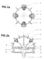
- Figures 2a and 2b illustrate the case where the diaphragms includes, in addition to diaphragm 5 whose functions are exposed above, a diaphragm 10 cooled with water, adjustable hole, the diameter of which is smaller than that of the plasma flow and which only allows the flow of gas activated.
- the diaphragm 10 is fixed to the enclosure by through a circular wall 11.
- the gas from nozzles (9) as well as the activating plasma are evacuated by through orifices 12.
- This diaphragm eliminates peripheral plasma gases and accompanying gases which are an obstacle to the diffusion of activated particles towards the surface to be treated.
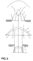
- the diaphragm 10 also makes it possible to obtain a uniform distribution of temperature and composition of the activated stream from the proposed generator.
Landscapes
- Physics & Mathematics (AREA)
- Engineering & Computer Science (AREA)
- Plasma & Fusion (AREA)
- Spectroscopy & Molecular Physics (AREA)
- Apparatus For Disinfection Or Sterilisation (AREA)
- Physical Or Chemical Processes And Apparatus (AREA)
- Plasma Technology (AREA)
- Nozzles (AREA)
- Water Treatment By Electricity Or Magnetism (AREA)
Description
- les figures 1a et 1b illustrent un premier exemple de
générateur selon l'invention, respectivement selon une vue du
côté du diaphragme (le diaphragme étant montré en traitillés)
et en section latérale; les repères relatifs à ces deux
figures sont les suivants:
- 1. Chambres à électrodes
- 2. Bride concave de l'enceinte, refroidie à l'eau
- 3. Buse d'introduction des composantes chimiques et/ou des matériaux à traiter.
- 4. Jets de plasma
- 5. Diaphragme plat refroidi à l'eau
- 6. Flux résultant de plasma
- 7. Système magnétique
- 8. Orifice circulaire du diaphragme
- 9. Tuyères d'introduction du gaz.
- les figures 2a et 2b illustrent un second exemple de
générateur selon l'invention, respectivement selon une vue du
côté des diaphragmes (les diaphragmes étant montrés en
traitillés) et en section latérale; les repères relatifs à ces
deux figures sont les suivants:
- 1. Chambres à électrodes
- 2. Bride concave de l'enceinte, refroidie à l'eau
- 3. Buse d'introduction des composantes chimiques et/ou des matériaux à traiter
- 4. Jets de plasma
- 5. Diaphragme plat refroidi à l'eau
- 6. Flux résultant de plasma
- 7. Système magnétique
- 8. Orifice circulaire du diaphragme
- 9. Tuyères d'introduction du gaz
- 10. Deuxième diaphragme, ajustable, refroidi à l'eau
- 11. Paroi circulaire
- 12. Orifice d'évacuation du plasma et du gaz introduit dans l'enceinte
- 13. Jet résultant de gaz activé
- la figure 3 est un schéma illustrant la fonction des diaphragmes d'après la distribution de la température (T) et de la composition (C) du flux issu du générateur, à différentes distances des chambres à électrodes.
Claims (2)
- Générateur de plasma à quatre buses comportant deux chambres à électrodes anodes (1) et deux chambres à électrodes cathodes (1), connectées à des sources de courant continu et générant quatre jets de plasma (4) dont la forme et la trajectoire sont créés à l'aide d'un système de champs magnétiques extérieurs (7), de telle manière que les jets de plasma forment un flux de plasma (6) unique présentant une zone centrale de température surbaissée dans laquelle est introduite la composante chimique et/ou le matériaux à traiter, caractérisé en ce que les chambres à électrodes sont disposées dans une enceinte dans laquelle on introduit un gaz, cette enceinte étant composée d'une bride concave (2) à laquelle sont fixées les chambres à électrodes et d'un premier diaphragme plat (5), refroidi à l'eau et pourvu d'un orifice central circulaire (8) disposé à l'endroit de la jonction des jets de plasma issus des chambres à électrodes et traversés par le courant.
- Générateur selon la revendication 1, caractérisé en ce qu'il comporte, en aval du premier diaphragme, un second diaphragme (10), refroidi à l'eau, dont l'orifice à un diamètre variable, inférieur à celui du flux de plasma, ce diaphragme étant fixé à l'enceinte par l'intermédiaire d'une paroi circulaire (11), permettant l'évacuation d'une partie du plasma et des gaz introduits dans l'enceinte.
Applications Claiming Priority (4)
| Application Number | Priority Date | Filing Date | Title |
|---|---|---|---|
| CH320895 | 1995-11-13 | ||
| CH3208/95 | 1995-11-13 | ||
| CH320895 | 1995-11-13 | ||
| PCT/CH1996/000401 WO1997018692A1 (fr) | 1995-11-13 | 1996-11-12 | Generateur de plasma a quatre buses pour la formation d'un jet active |
Publications (2)
| Publication Number | Publication Date |
|---|---|
| EP0861575A1 EP0861575A1 (fr) | 1998-09-02 |
| EP0861575B1 true EP0861575B1 (fr) | 2000-07-05 |
Family
ID=4251004
Family Applications (1)
| Application Number | Title | Priority Date | Filing Date |
|---|---|---|---|
| EP96934313A Expired - Lifetime EP0861575B1 (fr) | 1995-11-13 | 1996-11-12 | Generateur de plasma a quatre buses pour la formation d'un jet active |
Country Status (5)
| Country | Link |
|---|---|
| US (1) | US6278241B1 (fr) |
| EP (1) | EP0861575B1 (fr) |
| DE (1) | DE69609191T2 (fr) |
| ES (1) | ES2150693T3 (fr) |
| WO (1) | WO1997018692A1 (fr) |
Families Citing this family (14)
| Publication number | Priority date | Publication date | Assignee | Title |
|---|---|---|---|---|
| US6287687B1 (en) | 1998-05-08 | 2001-09-11 | Asten, Inc. | Structures and components thereof having a desired surface characteristic together with methods and apparatuses for producing the same |
| US6146462A (en) * | 1998-05-08 | 2000-11-14 | Astenjohnson, Inc. | Structures and components thereof having a desired surface characteristic together with methods and apparatuses for producing the same |
| EP1613133B1 (fr) * | 2000-11-10 | 2013-01-16 | Apit Corp. SA | Procédé de traitement par plasma atmosphérique de matériaux conducteurs d'électricité et dispositif pour sa mise en oeuvre |
| KR100464856B1 (ko) * | 2002-11-07 | 2005-01-05 | 삼성전자주식회사 | 표면 식각 방법 및 실리콘 기판 이면 식각 방법. |
| SG114754A1 (en) * | 2004-02-25 | 2005-09-28 | Kulicke & Soffa Investments | Laser cleaning system for a wire bonding machine |
| JP4449645B2 (ja) * | 2004-08-18 | 2010-04-14 | 島津工業有限会社 | プラズマ溶射装置 |
| FR2879933B1 (fr) * | 2004-12-28 | 2007-03-30 | Satelec Soc | Dispositif de sterilisation par plasma gazeux forme a partir d'un melange d'azote et d'hydrogene |
| US20060219754A1 (en) * | 2005-03-31 | 2006-10-05 | Horst Clauberg | Bonding wire cleaning unit and method of wire bonding using same |
| US9472382B2 (en) * | 2007-04-23 | 2016-10-18 | Plasmology4, Inc. | Cold plasma annular array methods and apparatus |
| GB0902784D0 (en) * | 2009-02-19 | 2009-04-08 | Gasplas As | Plasma reactor |
| DE102009045200B4 (de) * | 2009-09-30 | 2021-02-11 | Inter-Consult Gmbh | Verfahren und Vorrichtung zum Bearbeiten von Bauteilen elektrischer Maschinen |
| US8330069B2 (en) | 2010-09-16 | 2012-12-11 | General Electric Company | Apparatus and system for arc elmination and method of assembly |
| US9036309B2 (en) | 2010-09-16 | 2015-05-19 | General Electric Company | Electrode and plasma gun configuration for use with a circuit protection device |
| FR3074048B1 (fr) * | 2017-10-23 | 2024-08-30 | Soc Pour La Conception Des Applications Des Techniques Electroniques | Dispositif de sterilisation d’un objet avec deflecteur de flux |
Family Cites Families (5)
| Publication number | Priority date | Publication date | Assignee | Title |
|---|---|---|---|---|
| US4982067A (en) * | 1988-11-04 | 1991-01-01 | Marantz Daniel Richard | Plasma generating apparatus and method |
| WO1992012610A1 (fr) * | 1990-12-26 | 1992-07-23 | Inzhenerny Tsentr ''plazmodinamika'' | Dispositif de traitement de materiau a l'arc de plasma |
| GB2271124B (en) * | 1990-12-26 | 1995-09-27 | Opa | Method and apparatus for plasma treatment of a material |
| JP3166226B2 (ja) * | 1991-07-10 | 2001-05-14 | 住友電気工業株式会社 | ダイヤモンドの製造法及び製造装置 |
| WO1997046056A1 (fr) * | 1996-05-31 | 1997-12-04 | Ipec Precision, Inc. | Dispositif de production et de deviation d'un jet de plasma |
-
1996
- 1996-11-12 EP EP96934313A patent/EP0861575B1/fr not_active Expired - Lifetime
- 1996-11-12 ES ES96934313T patent/ES2150693T3/es not_active Expired - Lifetime
- 1996-11-12 WO PCT/CH1996/000401 patent/WO1997018692A1/fr not_active Ceased
- 1996-11-12 US US09/068,706 patent/US6278241B1/en not_active Expired - Fee Related
- 1996-11-12 DE DE69609191T patent/DE69609191T2/de not_active Expired - Fee Related
Also Published As
| Publication number | Publication date |
|---|---|
| WO1997018692A1 (fr) | 1997-05-22 |
| EP0861575A1 (fr) | 1998-09-02 |
| US6278241B1 (en) | 2001-08-21 |
| DE69609191T2 (de) | 2001-03-22 |
| ES2150693T3 (es) | 2000-12-01 |
| DE69609191D1 (de) | 2000-08-10 |
Similar Documents
| Publication | Publication Date | Title |
|---|---|---|
| EP0861575A1 (fr) | Generateur de plasma a quatre buses pour la formation d'un jet active | |
| US5622606A (en) | Gas inlet arrangement | |
| EP1420876B1 (fr) | Procede de fabrication de poudre de grains composites et dispositif pour la mise en oeuvre du procede | |
| EP0718552B1 (fr) | Brûleur du type à mélange externe | |
| WO2010110099A1 (fr) | Dispositif de traitement au plasma et procédé de fabrication d'une couche mince de silicium amorphe utilisant celui-ci | |
| JPH0543785B2 (fr) | ||
| FR2604050A1 (fr) | Appareil et procede de creation d'un faisceau monoenergetique de particules et produits obtenus par leur mise en oeuvre | |
| JPH057861B2 (fr) | ||
| JP2005276618A (ja) | マイクロプラズマ生成装置および方法 | |
| EP0815281B1 (fr) | Dispositif a microtete photo-ionique | |
| EP0914241B1 (fr) | Procede de traitement de surface par voie seche et dispositif pour la mise en oeuvre d'un tel procede | |
| US20140102639A1 (en) | Plasma treatment of hollow bodies | |
| FR2575938A1 (fr) | Procede et dispositif d'epuration de fumees soufrees et azotees | |
| Baranov et al. | Miniaturized plasma sources: Can technological solutions help electric micropropulsion? | |
| EP0815936A2 (fr) | Dispositif d'excitation de gaz | |
| FR2639363A1 (fr) | Procede et dispositif de traitement de surface par plasma, pour un substrat porte par une electrode | |
| CA2592618A1 (fr) | Dispositif de sterilisation par plasma gazeux forme a partir d'un melange d'azote et d'hydrogene | |
| FR2631164A3 (fr) | Dispositif d'amenee et de derivation de gaz pour le traitement en phase gazeuse de pieces | |
| EP2586276A1 (fr) | Dispositif pour la generation d'un jet de plasma | |
| FR2672459A1 (fr) | Dispositif de rechargement par plasma a orifice oblique. | |
| FR2573931A1 (fr) | Generateur laser a flux gazeux et procede de fonctionnement de ce generateur | |
| FR2551615A1 (fr) | Source de rayons x mous utilisant un microcanal de plasma obtenu par photo-ionisation d'un gaz | |
| RU2597447C2 (ru) | Лазерный способ получения функциональных покрытий | |
| EP3560299B1 (fr) | Réacteur plasma de dbd | |
| EP0861576B1 (fr) | Generateur de flux de plasma d'arc de configuration fermee |
Legal Events
| Date | Code | Title | Description |
|---|---|---|---|
| PUAI | Public reference made under article 153(3) epc to a published international application that has entered the european phase |
Free format text: ORIGINAL CODE: 0009012 |
|
| 17P | Request for examination filed |
Effective date: 19980515 |
|
| AK | Designated contracting states |
Kind code of ref document: A1 Designated state(s): CH DE ES FR GB IT LI NL |
|
| 17Q | First examination report despatched |
Effective date: 19981021 |
|
| GRAG | Despatch of communication of intention to grant |
Free format text: ORIGINAL CODE: EPIDOS AGRA |
|
| GRAG | Despatch of communication of intention to grant |
Free format text: ORIGINAL CODE: EPIDOS AGRA |
|
| GRAH | Despatch of communication of intention to grant a patent |
Free format text: ORIGINAL CODE: EPIDOS IGRA |
|
| GRAH | Despatch of communication of intention to grant a patent |
Free format text: ORIGINAL CODE: EPIDOS IGRA |
|
| GRAA | (expected) grant |
Free format text: ORIGINAL CODE: 0009210 |
|
| AK | Designated contracting states |
Kind code of ref document: B1 Designated state(s): CH DE ES FR GB IT LI NL |
|
| REG | Reference to a national code |
Ref country code: CH Ref legal event code: EP |
|
| REF | Corresponds to: |
Ref document number: 69609191 Country of ref document: DE Date of ref document: 20000810 |
|
| ITF | It: translation for a ep patent filed | ||
| GBT | Gb: translation of ep patent filed (gb section 77(6)(a)/1977) |
Effective date: 20001004 |
|
| REG | Reference to a national code |
Ref country code: CH Ref legal event code: NV Representative=s name: ABREMA AGENCE BREVETS ET MARQUES GANGUILLET & HUMP |
|
| REG | Reference to a national code |
Ref country code: ES Ref legal event code: FG2A Ref document number: 2150693 Country of ref document: ES Kind code of ref document: T3 |
|
| REG | Reference to a national code |
Ref country code: CH Ref legal event code: PUE Owner name: IST INSTANT SURFACE TECHNOLOGY S.A. TRANSFER- TEPL |
|
| REG | Reference to a national code |
Ref country code: GB Ref legal event code: 732E |
|
| REG | Reference to a national code |
Ref country code: CH Ref legal event code: NV Representative=s name: ABREMA AGENCE BREVETS ET MARQUES GANGUILLET & HUMP |
|
| NLS | Nl: assignments of ep-patents |
Owner name: TEPLA AG |
|
| RAP2 | Party data changed (patent owner data changed or rights of a patent transferred) |
Owner name: TEPLA AG |
|
| REG | Reference to a national code |
Ref country code: FR Ref legal event code: TP |
|
| PLBE | No opposition filed within time limit |
Free format text: ORIGINAL CODE: 0009261 |
|
| STAA | Information on the status of an ep patent application or granted ep patent |
Free format text: STATUS: NO OPPOSITION FILED WITHIN TIME LIMIT |
|
| NLT2 | Nl: modifications (of names), taken from the european patent patent bulletin |
Owner name: TEPLA AG |
|
| 26N | No opposition filed | ||
| PGFP | Annual fee paid to national office [announced via postgrant information from national office to epo] |
Ref country code: ES Payment date: 20011106 Year of fee payment: 6 |
|
| PGFP | Annual fee paid to national office [announced via postgrant information from national office to epo] |
Ref country code: GB Payment date: 20011109 Year of fee payment: 6 |
|
| PGFP | Annual fee paid to national office [announced via postgrant information from national office to epo] |
Ref country code: NL Payment date: 20011129 Year of fee payment: 6 Ref country code: FR Payment date: 20011129 Year of fee payment: 6 Ref country code: CH Payment date: 20011129 Year of fee payment: 6 |
|
| PGFP | Annual fee paid to national office [announced via postgrant information from national office to epo] |
Ref country code: DE Payment date: 20011221 Year of fee payment: 6 |
|
| REG | Reference to a national code |
Ref country code: GB Ref legal event code: IF02 |
|
| PG25 | Lapsed in a contracting state [announced via postgrant information from national office to epo] |
Ref country code: GB Free format text: LAPSE BECAUSE OF NON-PAYMENT OF DUE FEES Effective date: 20021112 |
|
| PG25 | Lapsed in a contracting state [announced via postgrant information from national office to epo] |
Ref country code: ES Free format text: LAPSE BECAUSE OF NON-PAYMENT OF DUE FEES Effective date: 20021113 |
|
| PG25 | Lapsed in a contracting state [announced via postgrant information from national office to epo] |
Ref country code: LI Free format text: LAPSE BECAUSE OF NON-PAYMENT OF DUE FEES Effective date: 20021130 Ref country code: CH Free format text: LAPSE BECAUSE OF NON-PAYMENT OF DUE FEES Effective date: 20021130 |
|
| PG25 | Lapsed in a contracting state [announced via postgrant information from national office to epo] |
Ref country code: NL Free format text: LAPSE BECAUSE OF NON-PAYMENT OF DUE FEES Effective date: 20030601 |
|
| PG25 | Lapsed in a contracting state [announced via postgrant information from national office to epo] |
Ref country code: DE Free format text: LAPSE BECAUSE OF NON-PAYMENT OF DUE FEES Effective date: 20030603 |
|
| GBPC | Gb: european patent ceased through non-payment of renewal fee | ||
| REG | Reference to a national code |
Ref country code: CH Ref legal event code: PL |
|
| PG25 | Lapsed in a contracting state [announced via postgrant information from national office to epo] |
Ref country code: FR Free format text: LAPSE BECAUSE OF NON-PAYMENT OF DUE FEES Effective date: 20030731 |
|
| NLV4 | Nl: lapsed or anulled due to non-payment of the annual fee |
Effective date: 20030601 |
|
| REG | Reference to a national code |
Ref country code: FR Ref legal event code: ST |
|
| REG | Reference to a national code |
Ref country code: ES Ref legal event code: FD2A Effective date: 20031213 |
|
| PG25 | Lapsed in a contracting state [announced via postgrant information from national office to epo] |
Ref country code: IT Free format text: LAPSE BECAUSE OF NON-PAYMENT OF DUE FEES;WARNING: LAPSES OF ITALIAN PATENTS WITH EFFECTIVE DATE BEFORE 2007 MAY HAVE OCCURRED AT ANY TIME BEFORE 2007. THE CORRECT EFFECTIVE DATE MAY BE DIFFERENT FROM THE ONE RECORDED. Effective date: 20051112 |