EP0860663A2 - Cadre d'échange de chaleur pour chauffer et/ou refroidir des locaux - Google Patents
Cadre d'échange de chaleur pour chauffer et/ou refroidir des locaux Download PDFInfo
- Publication number
- EP0860663A2 EP0860663A2 EP98200456A EP98200456A EP0860663A2 EP 0860663 A2 EP0860663 A2 EP 0860663A2 EP 98200456 A EP98200456 A EP 98200456A EP 98200456 A EP98200456 A EP 98200456A EP 0860663 A2 EP0860663 A2 EP 0860663A2
- Authority
- EP
- European Patent Office
- Prior art keywords
- frame according
- radiator
- heat exchanger
- frame
- heating
- Prior art date
- Legal status (The legal status is an assumption and is not a legal conclusion. Google has not performed a legal analysis and makes no representation as to the accuracy of the status listed.)
- Withdrawn
Links
Images


Classifications
-
- F—MECHANICAL ENGINEERING; LIGHTING; HEATING; WEAPONS; BLASTING
- F24—HEATING; RANGES; VENTILATING
- F24D—DOMESTIC- OR SPACE-HEATING SYSTEMS, e.g. CENTRAL HEATING SYSTEMS; DOMESTIC HOT-WATER SUPPLY SYSTEMS; ELEMENTS OR COMPONENTS THEREFOR
- F24D13/00—Electric heating systems
- F24D13/02—Electric heating systems solely using resistance heating, e.g. underfloor heating
- F24D13/022—Electric heating systems solely using resistance heating, e.g. underfloor heating resistances incorporated in construction elements
- F24D13/026—Electric heating systems solely using resistance heating, e.g. underfloor heating resistances incorporated in construction elements in door, windows
-
- Y—GENERAL TAGGING OF NEW TECHNOLOGICAL DEVELOPMENTS; GENERAL TAGGING OF CROSS-SECTIONAL TECHNOLOGIES SPANNING OVER SEVERAL SECTIONS OF THE IPC; TECHNICAL SUBJECTS COVERED BY FORMER USPC CROSS-REFERENCE ART COLLECTIONS [XRACs] AND DIGESTS
- Y02—TECHNOLOGIES OR APPLICATIONS FOR MITIGATION OR ADAPTATION AGAINST CLIMATE CHANGE
- Y02B—CLIMATE CHANGE MITIGATION TECHNOLOGIES RELATED TO BUILDINGS, e.g. HOUSING, HOUSE APPLIANCES OR RELATED END-USER APPLICATIONS
- Y02B30/00—Energy efficient heating, ventilation or air conditioning [HVAC]
Definitions
- This invention concerns a heat exchange frame for heating and/or cooling rooms, especially homes and offices.
- the heat exchangers normally available in the rooms of an apartment or an office may be of two kinds: fixed or mobile.
- the fixed heat exchangers are generally hung on a wall, for example near the window or door frames; the mobile heat exchangers are generally installed in a room by hanging them on a wall or leaving them in a mobile form on the floor, for the length of time their use is demanded by the outside weather conditions.
- a window or door frame for rooms, especially for apartment and offices characterised by comprising a heat exchanger directly built into the frame.
- Said heat exchanger is preferably placed in the lower part of the frame.
- a heat exchanger is set into a room without occupying extra space, thus maintaning heat comfort and enhancing aesthetics.
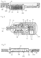
- FIGS 1 - 4 show an outward facing frame consisting of a two-pane door window. The lower part of one of these panes holds a built-in heat exchanger 100.
- This heat exchanger 100 includes a boxy housing 16 equipped with three grids 1, 2 and 3: two grids, 1 and 2, placed inside the room, are such as to allow the room air to enter the heat exchanger 100 to be heated and/or cooled, and one outer grid 3 is such as to draw air from the outside.
- Figure 3 shows a section of the frame of Figure 1, comprising the heat exchanger 100, along a plane III-III parallel to the floor.
- this shows, inside the housing 16, a finned radiator 11 capable of exchanging heat with a crossflow of air and a control panel 15 to adjust the air temperature and flowrate exiting the heat exchanger.
- FIG 4 shows a section of the frame of Figure 1, comprising the heat exchanger 100 along a plane IV-IV, in which the elements composing the heat exchanger are schematically represented.
- the heat exchanger comprises, in addition to the grids 1, 2 and 3, a mobile shutter 5 to allow an exchange with outside air.
- the air coming from the grids 1 and 3 crosses a filter 7 and reaches an electrical fan 6 which adjusts the flowrate.
- the flow then crosses a finned radiator while exchanging heat with the same, and exits across the grid 2, diffusing in the ambient.
- the air When the room air is to be cooled, the air enters the heat exchanger 100 through the grid 1, crosses the filter 7, then the electrical fan 6 and reaches the radiator 11. In contact with the radiator 11 the air condenses on the same and drips off.
- a collection basin is provided for the condensate ( Figure 4), fitted with a discharge hole 17 which is suitably connected to a means for removing the collected condensate.
- the radiator heating and/or cooling can be achieved directly inside the heat exchanger, for instance with the aid of an electrical air conditioning system or by exploiting a centralized heating (or cooling) system common to the entire apartment or office or all the apartments and offices of the same building.
- the pipes originating from the heating and/or cooling system must be connected to the radiator 11 fitted inside the frame, by using the appropriate fittings to be described below.
- connection To allow the opening of the frame the connection must guarantee a hydraulic seal, while at the same time allowing a relative rotation of its connected parts.
- Rotating joints 200 as shown in the cross section of Figure 5 are used for this purpose.
- the rotating joint 200 essentially comprises a first cylindrical body 51 and a second cylindrical body 52.
- the extremity of the first cylindrical body 51 forms a cavity 60 to hold the second internally hollow cylindrical body 52 and a second cavity 61.
- the extremity of this second cavity 61 is fitted with a threaded hole 54 with an axis transversal to the axis 59 of the cylindrical body 51, on which the terminal part of a pipe for connection with the radiator 11 is to be screwed.
- the extremity of the second cylindrical body 52 protruding from the body 51 is fitted with an externally threaded cylindrical section 53, suitable for a threaded connection to a corresponding pipe for connection with the heating and/cooling system.
- the relative rotation between the cylindrical bodies 51 and 52 around the axis 59 is achieved through a pair of roller bearings 58.
- the hydraulic seal is on the other hand guaranteed by the elements 55, 56 and 57.
- the element 55 is an essentially cylindrical and internally hollow front seal slipped inside the cavity 61 formed in the cylindrical body 51. Said element 55 is pushed against the cylindrical body 52 by a spring 57. The surfaces of the two elements 52, 55 in contact with each other are flat and ensure a seal between the cylindrical body 52 and the element 55 by the presence of a thin film of the liquid to be sealed off.
- the seal between the element 55 and the cylindrical body 51 is formed by a gasket 56, generally known as "O-ring gasket", mounted on a cylindrical section of the element 55 inside the cavity 61.
- Figure 3 shows a safety valve 30, fitted in a wall of the room, that shuts off the flow of the heating and/or cooling fluid in case of malfunctions of the heat exchanger 100.
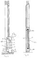
- Figure 6 - 8 show a second embodiment of the invention.
- FIG 6 is a front view of a single-pane frame with a heat exchanger 101 built into its lower part.
- the heat exchanger 101 consists of a radiator 31 of a radiating plate type, visible from the front but closed off in the rear by a protective wall 42 and laterally flanked by two aesthetic grids 21 and 22, which can eventually be extended even in front of the radiator 31, thus allowing the heat exchanging air to enter and exit.
- the radiator 31 is connected to a central heating system by two tubes 33, one coming and one going, and two corresponding rotating joints 200.
- two safety valves 40 are present which adjust the heating fluid flow depending on the requirements, and shut it off in case of any malfunction of the heat exchanger 101.
Landscapes
- Engineering & Computer Science (AREA)
- Physics & Mathematics (AREA)
- Thermal Sciences (AREA)
- Chemical & Material Sciences (AREA)
- Combustion & Propulsion (AREA)
- Mechanical Engineering (AREA)
- General Engineering & Computer Science (AREA)
- Special Wing (AREA)
- Securing Of Glass Panes Or The Like (AREA)
- Domestic Hot-Water Supply Systems And Details Of Heating Systems (AREA)
Applications Claiming Priority (2)
| Application Number | Priority Date | Filing Date | Title |
|---|---|---|---|
| IT97MI000387A IT1290546B1 (it) | 1997-02-24 | 1997-02-24 | Serramento a scambio termico per il riscaldamento e/o la refrigerazione di ambienti |
| ITMI970387 | 1997-02-24 |
Publications (2)
| Publication Number | Publication Date |
|---|---|
| EP0860663A2 true EP0860663A2 (fr) | 1998-08-26 |
| EP0860663A3 EP0860663A3 (fr) | 2000-04-12 |
Family
ID=11376135
Family Applications (1)
| Application Number | Title | Priority Date | Filing Date |
|---|---|---|---|
| EP98200456A Withdrawn EP0860663A3 (fr) | 1997-02-24 | 1998-02-13 | Cadre d'échange de chaleur pour chauffer et/ou refroidir des locaux |
Country Status (2)
| Country | Link |
|---|---|
| EP (1) | EP0860663A3 (fr) |
| IT (1) | IT1290546B1 (fr) |
Cited By (2)
| Publication number | Priority date | Publication date | Assignee | Title |
|---|---|---|---|---|
| NL1036745C2 (nl) * | 2009-03-20 | 2010-09-21 | Whitestone Corp S A | Deur. |
| EP2796797A3 (fr) * | 2013-03-28 | 2015-05-27 | Ribe Jernindustri A/S | Radiateur |
Citations (4)
| Publication number | Priority date | Publication date | Assignee | Title |
|---|---|---|---|---|
| FR2085473A1 (fr) * | 1970-04-24 | 1971-12-24 | Vey Jean | Ensemble d'installation chauffage et climatisation |
| FR2218458A1 (fr) * | 1973-02-16 | 1974-09-13 | Dentzer Noxa Groupe | |
| DE2337230A1 (de) * | 1973-07-21 | 1975-01-30 | Dieter Buehler | Tuer, insbesondere an gebaeuden, z.b. haus- oder zimmertuer, vorzugsweise badezimmertuer |
| FR2462666A1 (fr) * | 1979-07-30 | 1981-02-13 | Bancel Guy | Procede, installation et appareil pour le chauffage d'un local, notamment d'habitation |
-
1997
- 1997-02-24 IT IT97MI000387A patent/IT1290546B1/it active IP Right Grant
-
1998
- 1998-02-13 EP EP98200456A patent/EP0860663A3/fr not_active Withdrawn
Patent Citations (4)
| Publication number | Priority date | Publication date | Assignee | Title |
|---|---|---|---|---|
| FR2085473A1 (fr) * | 1970-04-24 | 1971-12-24 | Vey Jean | Ensemble d'installation chauffage et climatisation |
| FR2218458A1 (fr) * | 1973-02-16 | 1974-09-13 | Dentzer Noxa Groupe | |
| DE2337230A1 (de) * | 1973-07-21 | 1975-01-30 | Dieter Buehler | Tuer, insbesondere an gebaeuden, z.b. haus- oder zimmertuer, vorzugsweise badezimmertuer |
| FR2462666A1 (fr) * | 1979-07-30 | 1981-02-13 | Bancel Guy | Procede, installation et appareil pour le chauffage d'un local, notamment d'habitation |
Cited By (2)
| Publication number | Priority date | Publication date | Assignee | Title |
|---|---|---|---|---|
| NL1036745C2 (nl) * | 2009-03-20 | 2010-09-21 | Whitestone Corp S A | Deur. |
| EP2796797A3 (fr) * | 2013-03-28 | 2015-05-27 | Ribe Jernindustri A/S | Radiateur |
Also Published As
| Publication number | Publication date |
|---|---|
| IT1290546B1 (it) | 1998-12-10 |
| EP0860663A3 (fr) | 2000-04-12 |
| ITMI970387A1 (it) | 1998-08-24 |
Similar Documents
| Publication | Publication Date | Title |
|---|---|---|
| US6038879A (en) | Combined air exchange and air conditioning unit | |
| US5596981A (en) | Solar device and method for assembly | |
| US4126270A (en) | Solar energy collection system | |
| TW201944009A (zh) | 外氣空調機及換氣系統 | |
| CA2155628A1 (fr) | Appareil de renouvellement et de conditionnement d'air | |
| PL216199B1 (pl) | Wielosegmentowy grzejnik wyposażony w co najmniej dwa różne segmenty grzejne | |
| EP0860663A2 (fr) | Cadre d'échange de chaleur pour chauffer et/ou refroidir des locaux | |
| JP7463125B2 (ja) | 換気システム | |
| ITRE980039U1 (it) | Condizionatore d'aria monoblocco ad installazione facilitata. | |
| JPS6214734B2 (fr) | ||
| JP6286375B2 (ja) | ダブルスキンユニットおよびダブルスキンユニットを用いた空調システム | |
| CN206309257U (zh) | 遮阳元件、遮阳装置、窗户以及建筑物 | |
| EP2336472A1 (fr) | Cadre métallique pour portes et fenêtres avec radiateur d'eau comme isolation thermique | |
| CN215523534U (zh) | 一种窗帘盒式对流器 | |
| CN219494947U (zh) | 热管热回收节能风塔捕风器 | |
| CN211316451U (zh) | 一种通风装置 | |
| JP7388944B2 (ja) | 窓 | |
| EP3287713B1 (fr) | Façade ou élément de couverture modulaire avec mise à profit de l'énergie solaire pour le chauffage de l'eau, la climatisation et la ventilation | |
| EP1538402B1 (fr) | Capteur solaire intégré dans une façade | |
| PL215345B1 (pl) | Wielosegmentowy grzejnik wyposazony w co najmniej dwa rózne segmenty grzejne | |
| JPS60122856A (ja) | ソ−ラ−壁ユニツト | |
| KR200267297Y1 (ko) | 공기공급장치 | |
| JPH08320153A (ja) | ウォータウィンドシステム | |
| JPH0125982B2 (fr) | ||
| SE2050408A1 (en) | Heat recovery ventilation system |
Legal Events
| Date | Code | Title | Description |
|---|---|---|---|
| PUAI | Public reference made under article 153(3) epc to a published international application that has entered the european phase |
Free format text: ORIGINAL CODE: 0009012 |
|
| AK | Designated contracting states |
Kind code of ref document: A2 Designated state(s): AT BE CH DE DK ES FI FR GB GR IE IT LI LU MC NL PT SE |
|
| AX | Request for extension of the european patent |
Free format text: AL;LT;LV;MK;RO;SI |
|
| PUAL | Search report despatched |
Free format text: ORIGINAL CODE: 0009013 |
|
| AK | Designated contracting states |
Kind code of ref document: A3 Designated state(s): AT BE CH DE DK ES FI FR GB GR IE IT LI LU MC NL PT SE |
|
| AX | Request for extension of the european patent |
Free format text: AL;LT;LV;MK;RO;SI |
|
| AKX | Designation fees paid | ||
| REG | Reference to a national code |
Ref country code: DE Ref legal event code: 8566 |
|
| STAA | Information on the status of an ep patent application or granted ep patent |
Free format text: STATUS: THE APPLICATION IS DEEMED TO BE WITHDRAWN |
|
| 18D | Application deemed to be withdrawn |
Effective date: 20001013 |