EP0860319B1 - Rücksitzbank in einem Kraftfahrzeug - Google Patents
Rücksitzbank in einem Kraftfahrzeug Download PDFInfo
- Publication number
- EP0860319B1 EP0860319B1 EP98101507A EP98101507A EP0860319B1 EP 0860319 B1 EP0860319 B1 EP 0860319B1 EP 98101507 A EP98101507 A EP 98101507A EP 98101507 A EP98101507 A EP 98101507A EP 0860319 B1 EP0860319 B1 EP 0860319B1
- Authority
- EP
- European Patent Office
- Prior art keywords
- head rest
- operative position
- rest
- headrest
- supporting rods
- Prior art date
- Legal status (The legal status is an assumption and is not a legal conclusion. Google has not performed a legal analysis and makes no representation as to the accuracy of the status listed.)
- Expired - Lifetime
Links
- 230000006835 compression Effects 0.000 description 10
- 238000007906 compression Methods 0.000 description 10
- 238000006073 displacement reaction Methods 0.000 description 3
- 230000000694 effects Effects 0.000 description 3
- 235000013361 beverage Nutrition 0.000 description 2
- 206010027175 memory impairment Diseases 0.000 description 1
- 230000036316 preload Effects 0.000 description 1
- 230000001681 protective effect Effects 0.000 description 1
- 230000002040 relaxant effect Effects 0.000 description 1
Images

Classifications
-
- B—PERFORMING OPERATIONS; TRANSPORTING
- B60—VEHICLES IN GENERAL
- B60N—SEATS SPECIALLY ADAPTED FOR VEHICLES; VEHICLE PASSENGER ACCOMMODATION NOT OTHERWISE PROVIDED FOR
- B60N3/00—Arrangements or adaptations of other passenger fittings, not otherwise provided for
- B60N3/10—Arrangements or adaptations of other passenger fittings, not otherwise provided for of receptacles for food or beverages, e.g. refrigerated
- B60N3/102—Arrangements or adaptations of other passenger fittings, not otherwise provided for of receptacles for food or beverages, e.g. refrigerated storable or foldable in a non-use position
-
- B—PERFORMING OPERATIONS; TRANSPORTING
- B60—VEHICLES IN GENERAL
- B60N—SEATS SPECIALLY ADAPTED FOR VEHICLES; VEHICLE PASSENGER ACCOMMODATION NOT OTHERWISE PROVIDED FOR
- B60N2/00—Seats specially adapted for vehicles; Arrangement or mounting of seats in vehicles
- B60N2/75—Arm-rests
- B60N2/79—Adaptations for additional use of the arm-rests
- B60N2/793—Adaptations for additional use of the arm-rests for use as storage compartments
-
- B—PERFORMING OPERATIONS; TRANSPORTING
- B60—VEHICLES IN GENERAL
- B60N—SEATS SPECIALLY ADAPTED FOR VEHICLES; VEHICLE PASSENGER ACCOMMODATION NOT OTHERWISE PROVIDED FOR
- B60N2/00—Seats specially adapted for vehicles; Arrangement or mounting of seats in vehicles
- B60N2/80—Head-rests
- B60N2/806—Head-rests movable or adjustable
- B60N2/809—Head-rests movable or adjustable vertically slidable
- B60N2/832—Head-rests movable or adjustable vertically slidable movable to an inoperative or stowed position
- B60N2/835—Head-rests movable or adjustable vertically slidable movable to an inoperative or stowed position specially adapted for rear seats
-
- B—PERFORMING OPERATIONS; TRANSPORTING
- B60—VEHICLES IN GENERAL
- B60N—SEATS SPECIALLY ADAPTED FOR VEHICLES; VEHICLE PASSENGER ACCOMMODATION NOT OTHERWISE PROVIDED FOR
- B60N2/00—Seats specially adapted for vehicles; Arrangement or mounting of seats in vehicles
- B60N2/80—Head-rests
- B60N2/879—Head-rests with additional features not related to head-rest positioning, e.g. heating or cooling devices or loudspeakers
Definitions
- the invention relates to a rear seat in a motor vehicle in the Preamble of claim 1 and from DE-A-40 15 872 emerging art.
- the headrest known from this publication is on the two support rods Center armrest provided for longitudinal displacement.
- the headrest is swung up Armrest from one in the middle seat of the back seat manually located vehicle occupants.
- US-A-5,484,189 is on the back of a vehicle seat provided headrest disclosed, the support rod is in a tubular, in the backrest arranged housing is located. On this two are each other facing pads formed on which one is in a longitudinal groove Support rod located and against this in the rest position of the headrest Prestressing compression spring rests, the support rod via a transverse screw on one at the upper end portion of the Housing provided abuts. With a strong vehicle deceleration is achieved by the approximately horizontal displacement of the headrest the screw provided on the support rod in relation to the housing side Stop disengaged, causing the support rod and thus the headrest the effect of the relaxing compression spring from the rest position into one superscript active position is shifted.
- the object of the invention is therefore to provide one on a center armrest Headrest of the type mentioned in the preamble of claim 1 train that in a simple manner but always reliably in the active position brought.
- the support rods are advantageously each one Surround compression spring, which act against the headrest with pre-tension. This lies thereby in their active position on a stop of the support rods.
- the diameter of the mounting holes in the support rods Dimension the headrest so that it is spring-loaded so that it middle armrest in use position on two, diagonally opposite Corner areas of the mounting holes abuts a support rod. If the center armrest is in the swivel position, the headrest is turned around a vehicle transverse axis is pivoted so that the receiving holes about run coaxially to the support rods and thereby the headrest spring-loaded in the action is shifted.
- each support rod Locking element in such a frictional or form-fitting manner (via tangential grooves) Connection that in the event of a vehicle crash caused by this Swiveling the headrest between the locking element and the Support rod existing lock released and thereby the headrest the effect of the prestressed compression springs is shifted into their active position (Features of claims 1 and 2).
- the free end section of the support rods expediently extends in Position of use of the center armrest angled towards the seat part of the rear bench seat (Feature of claim 3).
- the rear seat 1 of a passenger car shown in FIG. 1 consists of a seat part 1 'and a backrest 1 ", in the longitudinal central region of which perpendicular recess 1 "'is provided.
- a Swivel pin 2 a center armrest 3 in the directions of the double arrow c pivoted.
- the center armrest 3 can also be between two individual backrests of the rear seat 1 are located.
- Figure 1 the approximately horizontal position of use a of the center armrest 3 with solid lines shown, while the swivel position b of the center armrest 3 with dash-dotted lines Lines is illustrated; the center armrest is in the central recess 1 "'of the backrest 1".
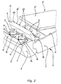
- the center armrest is at the free end region 3 two, spaced apart support rods 4 arranged on the free end portions protruding from the front of the center armrest 3 a headrest 5 is provided for longitudinal displacement.
- Each support rod is 4th surrounded by a compression spring 6, which with its inner end face support the center armrest 3, on the other hand with its free end side with preload act against the headrest 5.
- Compression springs 6 from the rest position d shown in solid lines in the Active position e (FIG. 1) shown with dash-dotted lines can be shifted as is explained below.
- the headrest 5 lies on one of the Support rod 4 on radially projecting stop 7.
- the provided in the headrest 5 Receiving holes each surround a support rod 4 with radial play. So that the headrest 5 can be shifted in a simple and convenient manner can, is the diameter of the mounting holes 4 surrounding the support holes dimensioned in the headrest 5 in this way and this by the compression springs 6 applies that the headrest 5 when in the position of use a center armrest 3 on two diagonally opposite corner areas of the mounting holes abuts on a support rod 4 and thereby held in the rest position d becomes.
- the center armrest 3 is in the swivel position b, the headrest 5 only so far about an axis extending over its longitudinal extent pivoted until the receiving holes run approximately coaxially to the support rods 4. Then the headrest 5 by the action of the compression springs 6 in the Action e shifted.
- a spring-loaded locking element 10 is provided. This is in such a way frictional or positive connection with the support rod 4 that in a crash the existing between the locking element 10 and the support rod 4 Lock is released and thereby the headrest 5 by the action of Compression springs 6 is shifted into their active position e.
- a Storage space 11 is provided for receiving various small parts.
- the headrest 5 is on the rear 5 ' Swivel cover 13 hinged up and down, the one in the closed position runs flush with the upper surface 12 'of the cover 12.
- the center armrest 3 there is a plate-shaped one Swivel part 18 hinged up and down, which in the swivel position g ( Figure 1) runs approximately flush with the surface 12 'of the cover 12 and thereby covering a cavity 19.
- the swivel part 18 can be shifted into the swivel position h, in which it faces the headrest 5 ( Figure 2).
- actuating elements 20 are provided, that can be comfortably operated by the vehicle occupant.
- the actuators 20 can for example be electrical, pneumatic or hydraulic Be switching elements.
Landscapes
- Engineering & Computer Science (AREA)
- Transportation (AREA)
- Mechanical Engineering (AREA)
- Aviation & Aerospace Engineering (AREA)
- Physics & Mathematics (AREA)
- Thermal Sciences (AREA)
- Seats For Vehicles (AREA)
Description
- Figur 1
- einen Vertikalschnitt der Rücksitzbank eines Personenkraftwagens im Bereich einer hoch- und niederschwenkbaren Mittelarmlehne,
- Figur 2
- eine perspektivische Darstellung des freien Endbereichs der Mittelarmlehne in ihrer Gebrauchslage.
Claims (3)
- Rücksitzbank (1) in einem Kraftfahrzeug mit einer zwischen einer Gebrauchslage (a) und einer etwa lotrechten Position verschwenkbaren Mittelarmlehne (3), die an ihrer freien Stirnseite eine von zwei Tragstangen (4) gehaltene Kopfstütze (5) trägt, welche durch die Wirkung wenigstens einer Druckfeder (6) aus einer Ruhelage (d) in eine Wirklage (e) bringbar ist, dadurch gekennzeichnet, dass beide Tragstangen (4) jeweils von einer sich an der Mittelarmlehne abstützenden Druckfeder (6) umgeben sind, die mit Vorspannung gegen die Kopfstütze (5) wirken, wobei der Durchmesser der die Tragstangen (4) umgebenden Aufnahmebohrungen in der Kopfstütze (5) derart bemessen ist, dassbei sich in Gebrauchslage (a) befindender Mittelarmlehne (3) die Aufnahmebohrungen durch die Wirkung der Druckfedem (6) über zwei schräg gegenüberliegende Eckbereiche gegen jeweils eine Tragstange (4) gepresst werden, wobei sich die Kopfstütze (5) in Ruhelage (d) befindet, währendbei sich in Hochschwenklage (b) befindender Mittelarmlehne (3) und einer Verschwenkung der die Kopfstütze (5) um eine über ihre Längserstreckung verlaufende Achse die Aufnahmebohrungen etwa koaxial zu den Tragstangen (4) verlaufen, wodurch schließlich die Kopfstütze (5) durch die Wirkung der Druckfedern (6) in die Wirklage (e) verlagert wird.
- Rücksitzbank nach Anspruch 1,
dadurch gekennzeichnet, dass mit mindestens einer Tragstange (4) ein an der Kopfstütze (5) vorgesehenes, federbelastetes Arretierelement (10) in derart reib- oder formschlüssiger Verbindung steht, dass die Kopfstütze (5) bei einem Crash durch die Wirkung der Druckfedern (6) in ihre Wirklage (e) verlagert wird. - Rücksitzbank nach Anspruch 1,
dadurch gekennzeichnet, dass der freie, von der Druckfeder (6) umgebene Endabschnitt der Tragstangen (4) in Gebrauchslage (a) der Mittelarmlehne (3) zum Sitzteil (1') der Rücksitzbank (1) hin abgewinkelt verläuft.
Applications Claiming Priority (2)
| Application Number | Priority Date | Filing Date | Title |
|---|---|---|---|
| DE19707477A DE19707477A1 (de) | 1997-02-25 | 1997-02-25 | Rücksitzbank in einem Kraftfahrzeug |
| DE19707477 | 1997-02-25 |
Publications (2)
| Publication Number | Publication Date |
|---|---|
| EP0860319A1 EP0860319A1 (de) | 1998-08-26 |
| EP0860319B1 true EP0860319B1 (de) | 2003-06-11 |
Family
ID=7821399
Family Applications (1)
| Application Number | Title | Priority Date | Filing Date |
|---|---|---|---|
| EP98101507A Expired - Lifetime EP0860319B1 (de) | 1997-02-25 | 1998-01-29 | Rücksitzbank in einem Kraftfahrzeug |
Country Status (2)
| Country | Link |
|---|---|
| EP (1) | EP0860319B1 (de) |
| DE (2) | DE19707477A1 (de) |
Families Citing this family (15)
| Publication number | Priority date | Publication date | Assignee | Title |
|---|---|---|---|---|
| DE19808404A1 (de) * | 1998-03-02 | 1999-09-09 | Butz Peter Verwaltung | Sitzanordnung für Fahrzeuge mit einem eine Halterungsaussparung, wie eine Durchladeaussparung einer Durchladeeinrichtung od. dgl., bildenden modulartigen Einbauteil |
| DE19834546A1 (de) * | 1998-07-31 | 2000-02-03 | Bayerische Motoren Werke Ag | Sitzbank eines Fahrzeuges |
| DE19860031B4 (de) * | 1998-12-23 | 2007-05-16 | Bayerische Motoren Werke Ag | Schwenkbar gelagerte Mittelarmlehne an einer Rücksitzbank eines Kraftfahrzeugs |
| GB2355651A (en) * | 1999-10-27 | 2001-05-02 | Lander Automotive Ltd | Armrest-headrest cup holder |
| DE10215152B8 (de) * | 2002-04-05 | 2007-11-22 | Grammer Ag | Armlehne für Kraftfahrzeugsitze, insbesondere Mittelarmlehne |
| DE102007031068B4 (de) * | 2007-07-04 | 2016-09-22 | GM Global Technology Operations LLC (n. d. Ges. d. Staates Delaware) | Fahrzeugsitz, Sitzanordnung und Kopfstütze |
| DE102008039555A1 (de) * | 2008-08-25 | 2010-03-04 | GM Global Technology Operations, Inc., Detroit | Kopfstütze |
| US9145075B2 (en) | 2010-09-28 | 2015-09-29 | Lear Corporation | Vehicle modular armrest |
| DE102012023482A1 (de) | 2012-11-30 | 2014-06-05 | Volkswagen Aktiengesellschaft | Armlehnen-Modul mit aufklappbarem Armauflageelement und Getränkehalterung |
| GB2554856B (en) * | 2016-09-28 | 2019-10-23 | Jaguar Land Rover Ltd | Apparatus and method for deploying a storage means for a vehicle seat |
| CN108545002B (zh) * | 2018-05-24 | 2023-09-05 | 宁波帅特龙集团有限公司 | 一种两段式车辆杯托装置 |
| CN111546950B (zh) * | 2020-05-06 | 2022-05-10 | 广州小鹏汽车制造有限公司 | 调整方法、调整装置、车辆和存储介质 |
| DE102021120445A1 (de) | 2021-08-05 | 2023-02-09 | M-motion-design GmbH | Armlehnenanordnung mit einem Armlehnenteil zum Verbau in einem Fond eines Kraftfahrzeugs |
| CN115027336A (zh) * | 2022-05-30 | 2022-09-09 | 蔚来汽车科技(安徽)有限公司 | 扶手组件和具有其的车辆 |
| CN116811739B (zh) * | 2022-12-21 | 2024-07-26 | 东风延锋盐城汽车座舱系统有限公司 | 一种储藏、观影两用汽车扶手箱 |
Family Cites Families (12)
| Publication number | Priority date | Publication date | Assignee | Title |
|---|---|---|---|---|
| FR1388773A (fr) * | 1963-11-26 | 1965-02-12 | Sièges de sécurité avec repose-tête escamotable | |
| DE3701419A1 (de) * | 1987-01-20 | 1988-07-28 | Ernst Hans Hellmut | Ausklappbare armlehne mit beschleunigungssensitiver verriegelung |
| IL83070A (en) * | 1987-07-02 | 1992-03-29 | Michal Lipschitz | Headrest for conveyance |
| DE4015872C1 (en) * | 1990-05-17 | 1992-01-02 | Bayerische Motoren Werke Ag, 8000 Muenchen, De | Rear seat for motor vehicle - has headrest connected to top of armrest for selective use |
| DE4225880A1 (de) * | 1991-08-14 | 1993-02-18 | Volkswagen Ag | Sitzanordnung mit einem wahlweise als armlehne oder kopfstuetze zu benutzenden polsterelement |
| IT223321Z2 (it) * | 1991-10-15 | 1995-06-21 | Fiat Auto Spa | Bracciolo per un veicolo. |
| DE4222921C2 (de) * | 1992-07-11 | 1996-02-01 | Daimler Benz Ag | Höhenverschiebbare Kopfstütze für einen Kraftwagensitz |
| US5484189A (en) * | 1994-06-24 | 1996-01-16 | Patterson; James | Retractable pop-up head rest usable with a vehicle passenger seat |
| GB2301279B (en) * | 1995-04-08 | 1999-05-05 | Rover Group | Vehicle seating |
| FR2735732B1 (fr) * | 1995-06-26 | 1997-08-29 | Faure Bertrand Equipements Sa | Accoudoir rabattable, et siege de vehicule equipe d'un tel accoudoir |
| ES2120156T3 (es) * | 1995-10-23 | 1998-10-16 | Bruzolo Manifatt Gestind Mb | Reposacabezas para asiento de vehiculo automovil. |
| DE29619478U1 (de) * | 1996-11-11 | 1997-02-27 | F. S. Fehrer Gummihaar- Und Schaumpolsterfabrik Gmbh & Co Kg, 97318 Kitzingen | Fahrzeugsitzbank mit Mittelarmlehne und Kopfstütze |
-
1997
- 1997-02-25 DE DE19707477A patent/DE19707477A1/de not_active Ceased
-
1998
- 1998-01-29 DE DE59808663T patent/DE59808663D1/de not_active Expired - Fee Related
- 1998-01-29 EP EP98101507A patent/EP0860319B1/de not_active Expired - Lifetime
Also Published As
| Publication number | Publication date |
|---|---|
| DE59808663D1 (de) | 2003-07-17 |
| DE19707477A1 (de) | 1998-08-27 |
| EP0860319A1 (de) | 1998-08-26 |
Similar Documents
| Publication | Publication Date | Title |
|---|---|---|
| EP1142750B1 (de) | Sitzanordnung für Fahrzeuge | |
| DE69400336T2 (de) | Klappzusatzsitz für Fahrzeuge | |
| DE10066239B4 (de) | Kopfstütze an einem Fahrzeugsitz | |
| DE19742408B4 (de) | Sitzstruktur für ein Fahrzeug | |
| DE69406718T2 (de) | Mehrfachsitz für Kraftfahrzeuge | |
| DE60024274T2 (de) | Klappbare u-förmige kopfstütze | |
| DE19920536B4 (de) | Fahrzeugsitz, insbesondere für einen Lastkraftwagen | |
| DE102009021267B4 (de) | Kopfstütze mit Kopfstützen-Komfortflügeln | |
| DE19851027A1 (de) | Kopfstütze für Fahrzeugsitze | |
| EP0860319A1 (de) | Rücksitzbank in einem Kraftfahrzeug | |
| EP0359962B1 (de) | Sitz, insbesondere Kraftfahrzeugsitz | |
| DE4015872C1 (en) | Rear seat for motor vehicle - has headrest connected to top of armrest for selective use | |
| DE69305716T2 (de) | Kinderrückhaltesitz mit einer Schaum- und einer biegsamen Schicht | |
| DE3842733C2 (de) | Kraftfahrzeugsitz | |
| EP0143353A2 (de) | Polstersitz, insbesondere Polstersitzbank, für Fahrzeuge | |
| DE10043923A1 (de) | Fahrzeugsitz mit Kopfstütze | |
| DE19737643C2 (de) | Armlehnenanordnung für einen Sitz, insbesondere einen Kraftfahrzeugsitz | |
| DE29512686U1 (de) | Verstellmechanismus für eine Kraftfahrzeug-Mittelarmlehne | |
| DE10145240A1 (de) | Kopfstütze für Fahrzeugsitze | |
| DE10253186B4 (de) | Klappsitz | |
| DE3911264A1 (de) | Sitzanordnung in einem fahrzeug | |
| DE19716054C1 (de) | Kraftfahrzeugrückenlehne mit Kopfstütze | |
| DE4135092A1 (de) | Sitz, insbesondere kraftfahrzeugsitz | |
| DE10347380B4 (de) | Variable Kopfstütze | |
| DE9206088U1 (de) | Armlehne für Omnibussitz |
Legal Events
| Date | Code | Title | Description |
|---|---|---|---|
| PUAI | Public reference made under article 153(3) epc to a published international application that has entered the european phase |
Free format text: ORIGINAL CODE: 0009012 |
|
| AK | Designated contracting states |
Kind code of ref document: A1 Designated state(s): DE FR GB IT |
|
| AX | Request for extension of the european patent |
Free format text: AL;LT;LV;MK;RO;SI |
|
| 17P | Request for examination filed |
Effective date: 19980909 |
|
| AKX | Designation fees paid |
Free format text: DE FR GB IT |
|
| RBV | Designated contracting states (corrected) |
Designated state(s): DE FR GB IT |
|
| 17Q | First examination report despatched |
Effective date: 20020508 |
|
| GRAH | Despatch of communication of intention to grant a patent |
Free format text: ORIGINAL CODE: EPIDOS IGRA |
|
| GRAH | Despatch of communication of intention to grant a patent |
Free format text: ORIGINAL CODE: EPIDOS IGRA |
|
| GRAA | (expected) grant |
Free format text: ORIGINAL CODE: 0009210 |
|
| AK | Designated contracting states |
Designated state(s): DE FR GB IT |
|
| REG | Reference to a national code |
Ref country code: GB Ref legal event code: FG4D Free format text: NOT ENGLISH |
|
| GBT | Gb: translation of ep patent filed (gb section 77(6)(a)/1977) | ||
| REF | Corresponds to: |
Ref document number: 59808663 Country of ref document: DE Date of ref document: 20030717 Kind code of ref document: P |
|
| ET | Fr: translation filed | ||
| PLBE | No opposition filed within time limit |
Free format text: ORIGINAL CODE: 0009261 |
|
| STAA | Information on the status of an ep patent application or granted ep patent |
Free format text: STATUS: NO OPPOSITION FILED WITHIN TIME LIMIT |
|
| 26N | No opposition filed |
Effective date: 20040312 |
|
| PGFP | Annual fee paid to national office [announced via postgrant information from national office to epo] |
Ref country code: DE Payment date: 20070221 Year of fee payment: 10 |
|
| PGFP | Annual fee paid to national office [announced via postgrant information from national office to epo] |
Ref country code: IT Payment date: 20080130 Year of fee payment: 11 Ref country code: GB Payment date: 20080131 Year of fee payment: 11 |
|
| PGFP | Annual fee paid to national office [announced via postgrant information from national office to epo] |
Ref country code: FR Payment date: 20080128 Year of fee payment: 11 |
|
| PG25 | Lapsed in a contracting state [announced via postgrant information from national office to epo] |
Ref country code: DE Free format text: LAPSE BECAUSE OF NON-PAYMENT OF DUE FEES Effective date: 20080801 |
|
| GBPC | Gb: european patent ceased through non-payment of renewal fee |
Effective date: 20090129 |
|
| REG | Reference to a national code |
Ref country code: FR Ref legal event code: ST Effective date: 20091030 |
|
| PG25 | Lapsed in a contracting state [announced via postgrant information from national office to epo] |
Ref country code: GB Free format text: LAPSE BECAUSE OF NON-PAYMENT OF DUE FEES Effective date: 20090129 |
|
| PG25 | Lapsed in a contracting state [announced via postgrant information from national office to epo] |
Ref country code: FR Free format text: LAPSE BECAUSE OF NON-PAYMENT OF DUE FEES Effective date: 20090202 |
|
| PG25 | Lapsed in a contracting state [announced via postgrant information from national office to epo] |
Ref country code: IT Free format text: LAPSE BECAUSE OF NON-PAYMENT OF DUE FEES Effective date: 20090129 |