EP0859643B1 - Systeme de drainage de plaies - Google Patents
Systeme de drainage de plaies Download PDFInfo
- Publication number
- EP0859643B1 EP0859643B1 EP96935026A EP96935026A EP0859643B1 EP 0859643 B1 EP0859643 B1 EP 0859643B1 EP 96935026 A EP96935026 A EP 96935026A EP 96935026 A EP96935026 A EP 96935026A EP 0859643 B1 EP0859643 B1 EP 0859643B1
- Authority
- EP
- European Patent Office
- Prior art keywords
- vacuum
- line
- valve
- wound drainage
- bottle
- Prior art date
- Legal status (The legal status is an assumption and is not a legal conclusion. Google has not performed a legal analysis and makes no representation as to the accuracy of the status listed.)
- Expired - Lifetime
Links
Images


Classifications
-
- G—PHYSICS
- G05—CONTROLLING; REGULATING
- G05D—SYSTEMS FOR CONTROLLING OR REGULATING NON-ELECTRIC VARIABLES
- G05D16/00—Control of fluid pressure
- G05D16/04—Control of fluid pressure without auxiliary power
- G05D16/10—Control of fluid pressure without auxiliary power the sensing element being a piston or plunger
-
- A—HUMAN NECESSITIES
- A61—MEDICAL OR VETERINARY SCIENCE; HYGIENE
- A61M—DEVICES FOR INTRODUCING MEDIA INTO, OR ONTO, THE BODY; DEVICES FOR TRANSDUCING BODY MEDIA OR FOR TAKING MEDIA FROM THE BODY; DEVICES FOR PRODUCING OR ENDING SLEEP OR STUPOR
- A61M1/00—Suction or pumping devices for medical purposes; Devices for carrying-off, for treatment of, or for carrying-over, body-liquids; Drainage systems
- A61M1/64—Containers with integrated suction means
- A61M1/66—Pre-evacuated rigid containers, e.g. Redon bottles
-
- A—HUMAN NECESSITIES
- A61—MEDICAL OR VETERINARY SCIENCE; HYGIENE
- A61M—DEVICES FOR INTRODUCING MEDIA INTO, OR ONTO, THE BODY; DEVICES FOR TRANSDUCING BODY MEDIA OR FOR TAKING MEDIA FROM THE BODY; DEVICES FOR PRODUCING OR ENDING SLEEP OR STUPOR
- A61M1/00—Suction or pumping devices for medical purposes; Devices for carrying-off, for treatment of, or for carrying-over, body-liquids; Drainage systems
- A61M1/71—Suction drainage systems
- A61M1/73—Suction drainage systems comprising sensors or indicators for physical values
- A61M1/732—Visual indicating means for vacuum pressure
-
- A—HUMAN NECESSITIES
- A61—MEDICAL OR VETERINARY SCIENCE; HYGIENE
- A61M—DEVICES FOR INTRODUCING MEDIA INTO, OR ONTO, THE BODY; DEVICES FOR TRANSDUCING BODY MEDIA OR FOR TAKING MEDIA FROM THE BODY; DEVICES FOR PRODUCING OR ENDING SLEEP OR STUPOR
- A61M1/00—Suction or pumping devices for medical purposes; Devices for carrying-off, for treatment of, or for carrying-over, body-liquids; Drainage systems
- A61M1/71—Suction drainage systems
- A61M1/74—Suction control
- A61M1/743—Suction control by changing the cross-section of the line, e.g. flow regulating valves
Definitions
- the present invention relates to wound drainage systems.
- the suction flask is evacuated to a high level of vacuum, normally around 80 to 93,3 kPa (600 to 700 mm Hg).
- a flexible tube is connected to the flask and the other end of the tube is connected to a perforated wound drainage tube.
- the wound drainage tube is introduced into a hermetically sealed wound cavity. When the line from the flask is opened, the negative pressure prevailing in the flask acts in the wound cavity thus drawing off wound secretions down the line into the flask.
- the system may be safely disposed of.
- Flasks as described above are well-known and-such flasks are disclosed in, e.g. EP-A-288679 and Swiss Patents 596,840 and 584,037. However, as stated above, these flasks are charged with a high vacuum, e.g. around 96 kPa (720 mm Hg) and substantially all of that vacuum acts on the patient.
- a high vacuum e.g. around 96 kPa (720 mm Hg) and substantially all of that vacuum acts on the patient.
- the vacuum in the flask is adjusted to the desired level by first attaching a pressure measuring device to the neck of the flask.
- a valve is arranged between the flask and an adjustment device. The measuring device and adjustment device control the opening of the valve until the desired pressure is reached. The adjustment device is then removed and the wound drainage line is attached to the now low vacuum suction flask.
- WO 88/05319 discloses a wound drainage bottle which, in one embodiment, has a vacuum reducer to regulate vacuum levels in order to maintain a constant vacuum in the bottle throughout the entire filling process.
- a maximum vacuum is desirable in the suction flask in order to enable the greatest amount of wound secretion to be sucked into the flask before another flask is needed.
- the suction level in the wound region is too high for some applications.
- EP-B-0482029 aims to provide a flexible tube clip with a simple way of reducing the cross-section of a flexible tube in order to form a throttle restriction.
- this clip can act independently as a throttle valve.
- This system and other known systems use a bellows-type arrangement, integrally formed in a cap attached to the section flask.
- the regulation system is formed as an integral unit with the vacuum flask. It is thus necessary to purchase the whole system for a low vacuum requirement rather than converting an already charged high vacuum bottle for low vacuum use if desired.
- the regulation system should be suitable for converting existing, high vacuum flasks for low vacuum applications as required without requiring any modification to the currently used flasks.
- the flask can thus be used for either high or low vacuum applications.
- the present invention thus provides a low vacuum wound drainage system
- a low vacuum wound drainage system comprising a high vacuum bottle having on/off means to allow/prevent release of the vacuum from the bottle, and connector means for connection of a wound drainage line such that a vacuum path is provided between the bottle and the wound drainage line when the on/off means is in the on position; the system further comprising a wound drainage line adapted to be detachably connected to the vacuum bottle via the connector means to apply suction at a patient end of the line; and wherein a regulating valve is incorporated in the detachable wound drainage line, said valve acting to continuously regulate the vacuum in the line, said valve including a patient line port and a high vacuum port, the former being connected to a section of the wound drainage line leading to the patient and the latter being connected to a section of the wound drainage line leading to the high vacuum bottle; when the line is attached to the bottle, to provide a reduced vacuum at the patient end of the line; characterised in that said valve comprises a valve spool slidingly located within a valve
- the same high vacuum flask can be used for high vacuum applications by connecting a simple wound drainage tube, or can be used for low vacuum applications by connecting a wound drainage tube incorporating an in-line regulating valve.
- the flask may be of standard construction.
- the valve comprises a valve spool slidingly located within a valve body and held by a spring.
- the bellows system is also relatively bulky and cumbersome.
- the present system is easier to prime than a bellows system and is more compact.
- the system can be primed by initially pushing the valve spool inwards, against the force of the spring, before switching the system on.
- valve body, the ports and the connecting parts of the wound drainage line may be encased in a housing, part of the valve spool may project out from the housing to allow the valve to be primed before use by pressing the projecting part.
- a preferred embodiment incorporates a priming pin which engages the end of the valve spool, at one end. The other end extends out of the valve body so that it can be pushed in by the user. The pushing force is transmitted to the valve spool, pushing it in against the spring force.
- the priming pin is preferably in the form of a key which engages in the end of the valve spool.
- the pin preferably passes through a slot in the valve housing.
- the pin and the slot preferably cooperate such that after insertion into the slot, the pin can be rotated to a locked position to hold the valve in its primed position. Before use, the pin is rotated back to its unlocked position and removed.
- a high vacuum port is provided in the side of the valve body such that movement of the spool into the body, against the force of the spring, cuts off this port from the inside of the valve body, and hence cuts off the path from the high vacuum source to an outlet port on the patient line side of the valve.
- the spring rate is selected to control the degree of vacuum reduction from the high vacuum source to the patient line, such that the spring return force begins to act against the external atmospheric pressure acting on the opposite side of the spool when the vacuum in the patient line is at the desired level.
- the valve is provided in a flexible wound drainage line adapted to be attached to a standard pre-ch arged high vacuum flask or bottle.
- the vacuum is preferably reduced from the standard supplied high vacuum of 80 to 93 kPa (600 to 700 mm Hg) to a low vacuum of 13.3 to 26.6 kPa (100 to 200 mm Hg).
- the in-line regulating valve of the present invention can be used with standard high-vacuum flasks which can, if desired, be converted for use in low vacuum applications, the present invention provides a flexible wound drainage tube having a first section adapted to be connected to a high vacuum bottle and a second section to be applied to a wound, said first and second sections being interconnected via a regulating valve which acts to continuously provide a lower vacuum in the second section than that provided in the first section from the high vacuum bottle.
- the system of the present invention controls the reduction of vacuum to the patient to a controlled level and maintains that level whilst ensuring the containing wound drainage vessel fills to its capacity.
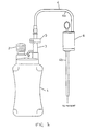
- Fig. 1 shows a wound drainage suction apparatus incorporating an in-line regulating valve in accordance with the present invention.
- the regulating device is positioned in the line between the patient and the collection vessel 1 which is also the high vacuum source.
- the vacuum source 1 is preferably a disposable, standard, pre-charged vacuum flask, supplied charged to a vacuum of 96 kPa (720 mm Hg).
- a volume scale may be marked on the bottle to show the fill level and the bottle is at least partially transparent. Because disposable systems are preferred, the bottle will normally be made of plastic.
- the standard bottles are provided with two openings.
- a bellows 2 is connected to one of these to provide an indication of the level of vacuum remaining in the flask 1. When the bellows 2 is at its maximum expansion, this indicates a minimum negative pressure or vacuum in the flask 1. A fully contracted bellows indicates a maximum vacuum.
- a tube 3 is connected to the other opening in the flask 1. In use, this tube 3 will be connected to a flexible wound drainage tube 4. Before use, the tube 3 is closed by a clamp 5 which pinches the tube 3 to maintain the vacuum in the flask 1.
- the bellows 2 and tube 3 may be enclosed in a plastic cap (not shown).
- the clamp 5 may also be enclosed in the cap and operated by an on/off switch on the outside of the cap.
- a port in the cap allows a wound drainage tube to be connected to the tube 3, in use.
- Vacuum is applied to the patient via a flexible wound drainage tube 4 attached, at one end, to the vacuum flask 1 via the tube 3.
- the clamp 5 is opened causing the negative pressure in the flask 1 to exist in the drainage tube 4 and to be applied to the patient at the other end of the tube 4.
- This causes fluid and wound secretions to be drawn up the wound drainage tube, by suction, into the flask 1 which acts as the collection vessel.
- the flask 1 is full, it is thrown away and a new charged vacuum flask is used.
- the aim of the present invention is to provide a constant low vacuum output at the patient end for as long as possible, to maximise efficiency and to allow the high vacuum source to be used for as long as possible.
- the vacuum at the patient end is constant at 13.3 kPa (100 mm Hg) while the high vacuum decreases from its initial value of say 96 kPa (720 mm Hg) to its finished, minimum value when it needs to be replaced.
- the present invention provides this vacuum regulation by use of a valve 6 located in the wound drainage tube 4.
- the valve is attached at its two ports between two sections 4a, 4b of the flexible wound drainage tube 4 as shown in Fig. 1.
- valve 6 The construction and operation of the valve 6 will now be described in more detail, with reference to Figs. 2 to 7.
- the valve 6 essentially comprises a valve body 10, a spool 11, an orifice 12 in the spool 11, a spring 13, seals 14 and vacuum ports 15, 16 to the vacuum source 1 and the patient respectively.
- the valve parts are all preferably enclosed in a housing 18.
- valve should be primed for use by initially depressing the spool 11 and then opening the clamp 5 to release the high vacuum.
- the preferred embodiment uses a priming pin 17 to prime the valve before use.
- the priming pin 17 is in the form of a key having a head 17a, adapted to be grasped by the user, and an elongate pin body 17b extending from the head 17a.
- the free end of the pin body 17b is shaped to engage in a notch or recess in the end of the valve spool 11.
- Openings are provided in the valve body 10 and the valve housing 6, aligned with the notch or recess in the end of the spool 11.
- the openings correspond to the diameter of the priming pin 17.
- the pin 17 can thus be inserted through the openings and engage in the valve spool 11.
- the pin body 17b also has a pair of locking projections extending radially from the body 17b near the pin head 17a.
- the opening in the valve housing 18 is provided with corresponding recesses.
- This arrangement allows the valve to be sold and/or transported in the primed state.
- the nurse or doctor only needs to unlock the pin by rotating it and then remove it after switching the device on.
- the device may be sold with the valve in the unprimed, relaxed, state. In that case, the nurse needs to prime the valve before use by inserting the pin and pushing it to push the valve spool inwards against the spring force.
- the orifice 12 passes over the seal 14 and is occluded by it thus cutting off the high vacuum.
- the point at which the orifice 12 passes over the seal 14 is the critical point at which the vacuum that has been allowed to develop in the patient line is the required low value, e.g. 13.3 kPa (100 mm Hg) . This value is determined by the relationship between the vacuum acting on the end of the cross-sectional area (C.S.A.) of the spool 11 and the spring force of the compressed spring 13. Wound secretions/fluid will then be drawn up the patient line by this lower regulated vacuum, into the valve body 10.
- the high vacuum will recharge the patient line until the spool 11 and its orifice 12 pass back over the seal 14 and also allows the material drawn up during the previous charge of the patient line to be passed into the collection vessel 1.
- the cycle thus continues, performing constant regulation of the vacuum in the patient line, until the vessel 1 is full.
- O-ring seals are provided on the valve body 10, shown in Figs. 2 and 3, essentially corresponding to the two ends of the valve spool 11. It was found, however, that the surface contact, and hence the resistance, between the valve spool 11 and the seals 14 was too great and the low vacuum output did not provide a smooth, constant level trace over time, when measured.
- One arrangement considered, shown in Fig. 6, involved providing seals on the valve spool 11 itself, rather than on the valve body. To further reduce the surface contact, the O-ring seals were replaced by rubber feather-tip seals. The area of contact was thus reduced to a point at each seal and the resistance was also reduced.
- one of the feather-tip seals was replaced by a flexible skirt 19 connected between the valve spool 11 and the valve body 10. The surface contact was thus reduced to a single point.
- the preferred embodiment shown in Figs. 4 and 5, thus uses seals on the valve body 10, corresponding to the ends of the sliding valve spool 11.
- the preferred seals are a unique combination of an O-ring seal with a feather-tip seal. Such a seal ensures reliable sealing whilst having a small surface contact with the spool, at the point of the feather-tip. This arrangement has been found to produce a smooth, constant level low vacuum output over the drainage bottle's fill duration.
- a further embodiment involves replacing one of the seals with a flexible skirt connected between the valve spool and the valve body.
- the seals 14 and spool 11 may be coated to provide virtually no resistance between the parts to increase the accuracy of the system.
- the present low vacuum system could be used to collect the blood by providing the above-described valve in the line between a high vacuum reservoir and a collection vessel.
- the preferred level of vacuum in this application is around 9.3 to 14.7 kPa (70 to 110 mm Hg).
- the present invention thus provides a neat, sophisticated, precise in-line vacuum regulating device for low vacuum medical use.
Abstract
Claims (7)
- Système de drainage de plaie sous faible vide, comprenant une bouteille sous vide élevé (1) pourvue d'un moyen d'ouverture / fermeture pour permettre / empêcher la purge du vide de la bouteille, et un connecteur pour raccordement d'un tube de drainage de plaie (4) de sorte qu'un chemin d'aspiration est créé entre la bouteille et le tube de drainage de plaie lorsque le moyen d'ouverture /fermeture est dans la position ouverte ; le système comprenant en outre un tube de drainage de plaie (4) prévu pour être raccordé de façon détachable à la bouteille sous vide par l'intermédiaire du connecteur afin d'appliquer une succion à une extrémité côté patient du tube ; et dans lequel une soupape de régulation (6) est incorporée dans le tube de drainage de plaie détachable, ladite soupape comprenant un orifice (15) pour tube de patient et un orifice (16) pour vide élevé, le premier étant raccordé à un segment du tube de drainage de plaie qui conduit au patient et le dernier étant raccordé à un segment du tube de drainage de plaie qui conduit à la bouteille sous vide élevé, ladite soupape agissant pour réguler de façon continue le vide dans le tube, lorsque le tube est raccordé à la bouteille, afin d'obtenir un vide réduit à l'extrémité côté patient du tube ; caractérisé en ce que ladite soupape (6) comprend un tiroir de soupape (11) logé de façon coulissante dans un corps de soupape (10) et tenu par un ressort (13) d'un côté et ouvert à la pression atmosphérique de l'autre côté, et dans lequel la constante d'élasticité du ressort est choisie de manière à régler le degré de réduction du vide entre la bouteille sous vide élevé et l'extrémité côté patient dudit tube de drainage de plaie, de sorte que la force de retour du ressort et la force résultant de la pression à l'extrémité côté patient dudit tube de drainage de plaie agissant sur le côté tube du tiroir sont égales à la pression atmosphérique extérieure agissant contre l'autre côté du tiroir lorsque le vide à ladite extrémité côté patient dudit tube de drainage de plaie est égal au vide réduit requis.
- Système selon la revendication 1, comprenant en outre une tige d'amorçage (17) prévue pour amener de force ledit tiroir de soupape (11) à une position amorcée, contre la force dudit ressort (13).
- Système selon la revendication 2, dans lequel ladite tige d'amorçage (17) est sous la forme d'une clé qui s'engage dans l'extrémité du tiroir de soupape (11).
- Système selon la revendication 2 ou 3, dans lequel ladite tige d'amorçage (17) comprend un moyen de verrouillage libérable, pour maintenir ladite tige dans sa position amorcée.
- Système selon une quelconque des revendications précédentes, dans lequel un orifice sous vide élevé est prévu dans le côté du corps de soupape de sorte qu'un mouvement du tiroir (11) dans le corps (10), contre la force du ressort (13), isole cet orifice de l'intérieur du corps de soupape et ferme donc le chemin allant de la bouteille sous vide élevé à l'orifice de tube de patient, dans ledit corps de soupape.
- Système selon une quelconque des revendications précédentes, comprenant un moyen d'étanchéité (14) agencé entre le tiroir de soupape et le corps de soupape.
- Système selon la revendication 6, dans lequel ledit moyen d'étanchéité comprend des garnitures d'étanchéité (14) ayant une configuration combinée de joint torique et de joint à lèvre.
Applications Claiming Priority (3)
| Application Number | Priority Date | Filing Date | Title |
|---|---|---|---|
| GBGB9521397.1A GB9521397D0 (en) | 1995-10-18 | 1995-10-18 | Wound drainage system |
| GB9521397 | 1995-10-18 | ||
| PCT/GB1996/002549 WO1997014449A2 (fr) | 1995-10-18 | 1996-10-17 | Systeme de drainage de plaies |
Publications (2)
| Publication Number | Publication Date |
|---|---|
| EP0859643A1 EP0859643A1 (fr) | 1998-08-26 |
| EP0859643B1 true EP0859643B1 (fr) | 2004-01-21 |
Family
ID=10782540
Family Applications (1)
| Application Number | Title | Priority Date | Filing Date |
|---|---|---|---|
| EP96935026A Expired - Lifetime EP0859643B1 (fr) | 1995-10-18 | 1996-10-17 | Systeme de drainage de plaies |
Country Status (10)
| Country | Link |
|---|---|
| US (1) | US6024731A (fr) |
| EP (1) | EP0859643B1 (fr) |
| JP (1) | JP3416144B2 (fr) |
| AU (1) | AU710959B2 (fr) |
| CA (1) | CA2234746C (fr) |
| DE (1) | DE69631377T2 (fr) |
| ES (1) | ES2210394T3 (fr) |
| GB (2) | GB9521397D0 (fr) |
| PT (1) | PT859643E (fr) |
| WO (1) | WO1997014449A2 (fr) |
Families Citing this family (47)
| Publication number | Priority date | Publication date | Assignee | Title |
|---|---|---|---|---|
| CA2235272C (fr) * | 1995-10-20 | 2006-08-22 | Harvest Technologies Llc | Systeme pour recueillir du sang sans l'abimer |
| US6478770B1 (en) * | 1997-07-07 | 2002-11-12 | Bahman Litkouhi | Apparatus and method for removing a lodged mass from an animal airway |
| US6447491B1 (en) | 1999-06-18 | 2002-09-10 | Genzyme Corporation | Rolling seal suction pressure regulator, apparatus and system for draining a body cavity and methods related thereto |
| CA2446250C (fr) * | 2001-05-02 | 2009-07-14 | Axiom Medical Inc. | Necessaire de drain percutane pour fluides |
| GB0113750D0 (en) * | 2001-06-06 | 2001-07-25 | Rocket Medical Plc | Autologous blood transfusion apparatus |
| US20030069551A1 (en) * | 2001-10-05 | 2003-04-10 | Axiom Medical, Inc. | Multipurpose drain |
| US6648862B2 (en) | 2001-11-20 | 2003-11-18 | Spheric Products, Ltd. | Personally portable vacuum desiccator |
| US8439893B2 (en) * | 2002-06-11 | 2013-05-14 | Medela Holding Ag | System and method for efficient drainage of body cavity |
| US6770062B2 (en) * | 2002-08-07 | 2004-08-03 | Trinh D. Phung | Automatic high negative pressure relief valve and chest drainage units using same |
| US7846141B2 (en) * | 2002-09-03 | 2010-12-07 | Bluesky Medical Group Incorporated | Reduced pressure treatment system |
| GB0224986D0 (en) | 2002-10-28 | 2002-12-04 | Smith & Nephew | Apparatus |
| US20050002810A1 (en) * | 2002-11-26 | 2005-01-06 | William Gould | Portable vacuum system |
| US7048724B2 (en) * | 2002-12-17 | 2006-05-23 | Denver Biomedicals, Inc. | Device for withdrawing body fluids |
| US20050065484A1 (en) * | 2003-09-10 | 2005-03-24 | Watson Richard L. | Wound healing apparatus with bioabsorbable material and suction tubes |
| FR2861282B1 (fr) * | 2003-10-27 | 2007-07-06 | Patrice Richard | Dispositif de prelevement de sang placentaire. |
| GB0325129D0 (en) | 2003-10-28 | 2003-12-03 | Smith & Nephew | Apparatus in situ |
| GB2407508B (en) * | 2003-10-31 | 2005-09-28 | Angus Buchan Gordon | Closed sterile drainage device |
| US8636721B2 (en) | 2003-11-20 | 2014-01-28 | Henry M. Jackson Foundation For The Advancement Of Military Medicine, Inc. | Portable hand pump for evacuation of fluids |
| US20050197647A1 (en) * | 2004-03-02 | 2005-09-08 | Dolliver Phillip B. | Surgical wound drain tube with flow control safeguards |
| US7790945B1 (en) | 2004-04-05 | 2010-09-07 | Kci Licensing, Inc. | Wound dressing with absorption and suction capabilities |
| US8337475B2 (en) | 2004-10-12 | 2012-12-25 | C. R. Bard, Inc. | Corporeal drainage system |
| WO2007038643A1 (fr) | 2005-09-26 | 2007-04-05 | C.R. Bard, Inc. | Systèmes de raccord de cathéther |
| US8025650B2 (en) * | 2006-06-12 | 2011-09-27 | Wound Care Technologies, Inc. | Negative pressure wound treatment device, and methods |
| RU2417110C2 (ru) | 2006-10-13 | 2011-04-27 | КейСиАй Лайсензинг Инк. | Система подачи пониженного давления, имеющая активируемый вручную насос для обеспечения лечения ран низкой степени тяжести |
| US8287507B2 (en) * | 2006-10-13 | 2012-10-16 | Kci Licensing, Inc. | Reduced pressure indicator for a reduced pressure source |
| JP5345555B2 (ja) * | 2007-02-09 | 2013-11-20 | ケーシーアイ ライセンシング インコーポレイテッド | 組織部位に減圧を適用するシステムおよび方法 |
| CN103893846B (zh) * | 2008-05-02 | 2017-05-24 | 凯希特许有限公司 | 具有调节压力能力的手动致动减压治疗泵 |
| EP2977068B1 (fr) | 2008-07-11 | 2017-10-11 | KCI Licensing, Inc. | Systèmes à pression réduite à actionnement manuel pour traiter des plaies |
| US9999710B2 (en) | 2009-01-07 | 2018-06-19 | Med-Logics, Inc. | Tissue removal devices, systems and methods |
| US20120089080A1 (en) * | 2009-01-07 | 2012-04-12 | Enlighten Technologies, Inc. | Tissue removal devices, systems and methods |
| US8882678B2 (en) | 2009-03-13 | 2014-11-11 | Atrium Medical Corporation | Pleural drainage system and method of use |
| GB201011173D0 (en) | 2010-07-02 | 2010-08-18 | Smith & Nephew | Provision of wound filler |
| AU2011333538C1 (en) | 2010-11-25 | 2015-07-30 | Bluestar Silicones France Sas | Composition I-II and products and uses thereof |
| GB201020005D0 (en) | 2010-11-25 | 2011-01-12 | Smith & Nephew | Composition 1-1 |
| US9050175B2 (en) | 2011-01-20 | 2015-06-09 | Scott Stephan | Therapeutic treatment pad |
| US20150159066A1 (en) | 2011-11-25 | 2015-06-11 | Smith & Nephew Plc | Composition, apparatus, kit and method and uses thereof |
| US20130226114A1 (en) * | 2012-02-29 | 2013-08-29 | Shayna Massi | Drainage system |
| US20160120706A1 (en) | 2013-03-15 | 2016-05-05 | Smith & Nephew Plc | Wound dressing sealant and use thereof |
| EP2988711B1 (fr) | 2013-04-26 | 2018-11-07 | Med-Logics, Inc. | Dispositif de retrait de tissu |
| CN103315710A (zh) * | 2013-06-17 | 2013-09-25 | 无锡市第三人民医院 | 光电比色血液丢失计量笔及配套使用的引流瓶 |
| WO2016054051A1 (fr) | 2014-09-29 | 2016-04-07 | Theranova, Llc | Dispositifs et procédés de gestion du drainage thoracique |
| CN104800899A (zh) * | 2015-04-16 | 2015-07-29 | 苏州瑞华医院有限公司 | 一种防堵塞负压引流装置 |
| DE202016100155U1 (de) | 2016-01-14 | 2017-04-20 | Pfm Medical Ag | Unterdruckbehältnis |
| CN105596034B (zh) * | 2016-02-27 | 2019-01-04 | 厦门大学附属中山医院 | 一种负压条件下的液体标本采集器 |
| AU2017299466B2 (en) | 2016-07-18 | 2022-07-14 | Merit Medical Systems, Inc. | Inflatable radial artery compression device |
| TWI747361B (zh) * | 2020-07-04 | 2021-11-21 | 輔仁大學學校財團法人輔仁大學 | 用於術後傷口之負壓引流裝置 |
| WO2023244215A1 (fr) * | 2022-06-14 | 2023-12-21 | Bard Peripheral Vascular, Inc. | Conduits de drainage à lumières multiples avec lumière pré-évacuée et lumière de drainage pour drainer des fluides corporels |
Family Cites Families (12)
| Publication number | Priority date | Publication date | Assignee | Title |
|---|---|---|---|---|
| GB747667A (en) * | 1953-03-19 | 1956-04-11 | Hindmarch Thomas | Pressure relief valve |
| CH405851A (de) * | 1963-11-27 | 1966-01-15 | Gunzenhauser Ag J & R | Druckreduzierventil |
| US3624821A (en) * | 1969-09-17 | 1971-11-30 | Stanford A Henderson | Suction pump |
| US3833000A (en) * | 1972-06-02 | 1974-09-03 | H Bridgman | Medical aspiration system |
| US4112949A (en) * | 1976-11-15 | 1978-09-12 | Howmedica Inc. | Apparatus for collecting body fluid |
| US4372336A (en) * | 1980-06-17 | 1983-02-08 | Sherwood Medical Industries, Inc. | Chest drainage unit |
| DE3404382A1 (de) * | 1984-02-08 | 1985-08-14 | Anton Dr. 4400 Münster Härle | Saugflasche zum absaugen von sekreten aus wundhoehlen |
| US4675011A (en) * | 1984-05-04 | 1987-06-23 | Bioresearch Inc. | Surgical drainage apparatus |
| DE3539955A1 (de) * | 1985-11-11 | 1987-05-14 | Isg Ag | Vakuumreguliergeraet |
| WO1988005319A1 (fr) * | 1987-01-20 | 1988-07-28 | Medinorm Aktiengesellschaft Medizintechnische Prod | Dispositif pour aspirer les fluides des blessures |
| US4930997A (en) * | 1987-08-19 | 1990-06-05 | Bennett Alan N | Portable medical suction device |
| US5236425A (en) * | 1990-08-29 | 1993-08-17 | Bioresearch, Inc. | Self-adjusting suction regulator |
-
1995
- 1995-10-18 GB GBGB9521397.1A patent/GB9521397D0/en active Pending
-
1996
- 1996-10-17 AU AU73129/96A patent/AU710959B2/en not_active Ceased
- 1996-10-17 US US09/051,683 patent/US6024731A/en not_active Expired - Lifetime
- 1996-10-17 WO PCT/GB1996/002549 patent/WO1997014449A2/fr active IP Right Grant
- 1996-10-17 JP JP51561697A patent/JP3416144B2/ja not_active Expired - Lifetime
- 1996-10-17 EP EP96935026A patent/EP0859643B1/fr not_active Expired - Lifetime
- 1996-10-17 CA CA002234746A patent/CA2234746C/fr not_active Expired - Fee Related
- 1996-10-17 PT PT96935026T patent/PT859643E/pt unknown
- 1996-10-17 ES ES96935026T patent/ES2210394T3/es not_active Expired - Lifetime
- 1996-10-17 GB GB9808205A patent/GB2322559B/en not_active Revoked
- 1996-10-17 DE DE69631377T patent/DE69631377T2/de not_active Expired - Lifetime
Also Published As
| Publication number | Publication date |
|---|---|
| DE69631377D1 (de) | 2004-02-26 |
| DE69631377T2 (de) | 2004-07-01 |
| CA2234746C (fr) | 2002-09-24 |
| EP0859643A1 (fr) | 1998-08-26 |
| GB2322559B (en) | 1999-08-04 |
| GB9521397D0 (en) | 1995-12-20 |
| AU7312996A (en) | 1997-05-07 |
| CA2234746A1 (fr) | 1997-04-24 |
| WO1997014449A2 (fr) | 1997-04-24 |
| WO1997014449A3 (fr) | 1998-08-20 |
| GB2322559A (en) | 1998-09-02 |
| US6024731A (en) | 2000-02-15 |
| GB9808205D0 (en) | 1998-06-17 |
| PT859643E (pt) | 2004-06-30 |
| ES2210394T3 (es) | 2004-07-01 |
| AU710959B2 (en) | 1999-09-30 |
| JP3416144B2 (ja) | 2003-06-16 |
| JPH11514271A (ja) | 1999-12-07 |
Similar Documents
| Publication | Publication Date | Title |
|---|---|---|
| EP0859643B1 (fr) | Systeme de drainage de plaies | |
| US5685864A (en) | Locking device for aspirator, syringe or like instrument | |
| US5098377A (en) | Multimodal displacement pump and dissolution system for same | |
| US4058123A (en) | Combined irrigator and evacuator for closed wounds | |
| JP3359949B2 (ja) | 創傷からの血液の収集及び血液の再注入装置 | |
| EP0362822B1 (fr) | Cassette à jeter pour système de pompe péristaltique/à vide | |
| US4981474A (en) | Body fluid drainage device | |
| US6174306B1 (en) | Device for vacuum-sealing an injury | |
| US4735606A (en) | Chest drainage apparatus | |
| US5207638A (en) | Blood transfer apparatus | |
| US5588958A (en) | Closed wound orthopaedic drainage and autotransfusion system | |
| CA1148050A (fr) | Dispositif generateur d'impulsions positives | |
| US5496299A (en) | Suction reservoir | |
| US5074839A (en) | Blood transfer apparatus | |
| JPH078552A (ja) | 外科用吸引装置 | |
| JPS61501581A (ja) | 脈動ポンプ | |
| EP0764033A1 (fr) | Vide controle en chirurgie oculaire retinienne | |
| US5554293A (en) | Disposable blood washing and apheresis device and method of using thereof | |
| JPH0442024B2 (fr) | ||
| US4284502A (en) | Apparatus for treating uremic patients | |
| WO2000076563A1 (fr) | Regulateur intermittent | |
| US5163926A (en) | Suction metering and mixing device | |
| AU6041190A (en) | Combined hemofiltration and hemodialysis system | |
| US4595004A (en) | Apparatus for the treatment of the lungs of humans or animals | |
| WO1981002523A1 (fr) | Drain de blessure |
Legal Events
| Date | Code | Title | Description |
|---|---|---|---|
| PUAI | Public reference made under article 153(3) epc to a published international application that has entered the european phase |
Free format text: ORIGINAL CODE: 0009012 |
|
| 17P | Request for examination filed |
Effective date: 19980511 |
|
| AK | Designated contracting states |
Kind code of ref document: A1 Designated state(s): BE DE ES FR GB IE IT NL PT SE |
|
| 17Q | First examination report despatched |
Effective date: 20020404 |
|
| RAP1 | Party data changed (applicant data changed or rights of an application transferred) |
Owner name: SUMMIT MEDICAL LIMITED |
|
| GRAH | Despatch of communication of intention to grant a patent |
Free format text: ORIGINAL CODE: EPIDOS IGRA |
|
| GRAS | Grant fee paid |
Free format text: ORIGINAL CODE: EPIDOSNIGR3 |
|
| 111Z | Information provided on other rights and legal means of execution |
Free format text: BEDEESFRGBIEITNLPTSE Effective date: 20030812 |
|
| GRAA | (expected) grant |
Free format text: ORIGINAL CODE: 0009210 |
|
| AK | Designated contracting states |
Kind code of ref document: B1 Designated state(s): BE DE ES FR GB IE IT NL PT SE |
|
| REG | Reference to a national code |
Ref country code: GB Ref legal event code: FG4D |
|
| REG | Reference to a national code |
Ref country code: IE Ref legal event code: FG4D |
|
| REF | Corresponds to: |
Ref document number: 69631377 Country of ref document: DE Date of ref document: 20040226 Kind code of ref document: P |
|
| REG | Reference to a national code |
Ref country code: SE Ref legal event code: TRGR |
|
| REG | Reference to a national code |
Ref country code: PT Ref legal event code: SC4A Free format text: AVAILABILITY OF NATIONAL TRANSLATION Effective date: 20040412 |
|
| REG | Reference to a national code |
Ref country code: ES Ref legal event code: FG2A Ref document number: 2210394 Country of ref document: ES Kind code of ref document: T3 |
|
| ET | Fr: translation filed | ||
| PLBE | No opposition filed within time limit |
Free format text: ORIGINAL CODE: 0009261 |
|
| STAA | Information on the status of an ep patent application or granted ep patent |
Free format text: STATUS: NO OPPOSITION FILED WITHIN TIME LIMIT |
|
| 26N | No opposition filed |
Effective date: 20041022 |
|
| PGFP | Annual fee paid to national office [announced via postgrant information from national office to epo] |
Ref country code: PT Payment date: 20130417 Year of fee payment: 18 |
|
| PGFP | Annual fee paid to national office [announced via postgrant information from national office to epo] |
Ref country code: BE Payment date: 20131022 Year of fee payment: 18 Ref country code: FR Payment date: 20131031 Year of fee payment: 18 Ref country code: IE Payment date: 20131018 Year of fee payment: 18 Ref country code: SE Payment date: 20131018 Year of fee payment: 18 Ref country code: DE Payment date: 20131024 Year of fee payment: 18 Ref country code: GB Payment date: 20131021 Year of fee payment: 18 |
|
| PGFP | Annual fee paid to national office [announced via postgrant information from national office to epo] |
Ref country code: NL Payment date: 20131022 Year of fee payment: 18 Ref country code: ES Payment date: 20131009 Year of fee payment: 18 Ref country code: IT Payment date: 20131028 Year of fee payment: 18 |
|
| REG | Reference to a national code |
Ref country code: PT Ref legal event code: MM4A Free format text: LAPSE DUE TO NON-PAYMENT OF FEES Effective date: 20150417 |
|
| REG | Reference to a national code |
Ref country code: DE Ref legal event code: R119 Ref document number: 69631377 Country of ref document: DE |
|
| REG | Reference to a national code |
Ref country code: NL Ref legal event code: V1 Effective date: 20150501 |
|
| REG | Reference to a national code |
Ref country code: SE Ref legal event code: EUG |
|
| GBPC | Gb: european patent ceased through non-payment of renewal fee |
Effective date: 20141017 |
|
| PG25 | Lapsed in a contracting state [announced via postgrant information from national office to epo] |
Ref country code: BE Free format text: LAPSE BECAUSE OF NON-PAYMENT OF DUE FEES Effective date: 20141031 |
|
| REG | Reference to a national code |
Ref country code: IE Ref legal event code: MM4A |
|
| PG25 | Lapsed in a contracting state [announced via postgrant information from national office to epo] |
Ref country code: GB Free format text: LAPSE BECAUSE OF NON-PAYMENT OF DUE FEES Effective date: 20141017 Ref country code: SE Free format text: LAPSE BECAUSE OF NON-PAYMENT OF DUE FEES Effective date: 20141018 Ref country code: PT Free format text: LAPSE BECAUSE OF NON-PAYMENT OF DUE FEES Effective date: 20150417 Ref country code: DE Free format text: LAPSE BECAUSE OF NON-PAYMENT OF DUE FEES Effective date: 20150501 |
|
| REG | Reference to a national code |
Ref country code: FR Ref legal event code: ST Effective date: 20150630 |
|
| PG25 | Lapsed in a contracting state [announced via postgrant information from national office to epo] |
Ref country code: FR Free format text: LAPSE BECAUSE OF NON-PAYMENT OF DUE FEES Effective date: 20141031 Ref country code: IT Free format text: LAPSE BECAUSE OF NON-PAYMENT OF DUE FEES Effective date: 20141017 Ref country code: NL Free format text: LAPSE BECAUSE OF NON-PAYMENT OF DUE FEES Effective date: 20150501 |
|
| PG25 | Lapsed in a contracting state [announced via postgrant information from national office to epo] |
Ref country code: IE Free format text: LAPSE BECAUSE OF NON-PAYMENT OF DUE FEES Effective date: 20141017 |
|
| REG | Reference to a national code |
Ref country code: ES Ref legal event code: FD2A Effective date: 20151126 |
|
| PG25 | Lapsed in a contracting state [announced via postgrant information from national office to epo] |
Ref country code: ES Free format text: LAPSE BECAUSE OF NON-PAYMENT OF DUE FEES Effective date: 20141018 |