EP0858585B1 - Durchflussmesser - Google Patents
Durchflussmesser Download PDFInfo
- Publication number
- EP0858585B1 EP0858585B1 EP96937275A EP96937275A EP0858585B1 EP 0858585 B1 EP0858585 B1 EP 0858585B1 EP 96937275 A EP96937275 A EP 96937275A EP 96937275 A EP96937275 A EP 96937275A EP 0858585 B1 EP0858585 B1 EP 0858585B1
- Authority
- EP
- European Patent Office
- Prior art keywords
- disc
- housing
- foregoing
- exciter
- chamber
- Prior art date
- Legal status (The legal status is an assumption and is not a legal conclusion. Google has not performed a legal analysis and makes no representation as to the accuracy of the status listed.)
- Expired - Lifetime
Links
Images

Classifications
-
- G—PHYSICS
- G01—MEASURING; TESTING
- G01F—MEASURING VOLUME, VOLUME FLOW, MASS FLOW OR LIQUID LEVEL; METERING BY VOLUME
- G01F3/00—Measuring the volume flow of fluids or fluent solid material wherein the fluid passes through the meter in successive and more or less isolated quantities, the meter being driven by the flow
- G01F3/02—Measuring the volume flow of fluids or fluent solid material wherein the fluid passes through the meter in successive and more or less isolated quantities, the meter being driven by the flow with measuring chambers which expand or contract during measurement
- G01F3/04—Measuring the volume flow of fluids or fluent solid material wherein the fluid passes through the meter in successive and more or less isolated quantities, the meter being driven by the flow with measuring chambers which expand or contract during measurement having rigid movable walls
- G01F3/06—Measuring the volume flow of fluids or fluent solid material wherein the fluid passes through the meter in successive and more or less isolated quantities, the meter being driven by the flow with measuring chambers which expand or contract during measurement having rigid movable walls comprising members rotating in a fluid-tight or substantially fluid-tight manner in a housing
- G01F3/10—Geared or lobed impeller meters
Definitions
- the invention relates to a flow meter according to Generic term of claim 1.
- a generic flow meter is from EP 05 72 621 ago known.
- the flow meter disclosed there is used in petrol pumps for liquid fuel For example, gasoline, diesel or the like.
- the device must be calibratable his.
- such a device be as inexpensive to manufacture as possible and high Own service life.
- the measuring device described above has a housing in which two interlocking Screw spindles are arranged. The screw spindles are easily supported at the ends. The outer flanks of the screw spindles rotate with them minimum distance to the housing wall in corresponding Housing bores. Flows from one axis direction the liquid to be measured in the spindle arrangement and offsets the spindles according to the flow rate in rotation.
- the liquid occurs on the opposite Axle side out of the spindle arrangement and flows through a measuring chamber in which an exciter disk can rotate, which with one of the two Spindles is firmly connected.
- the in the liquid flow rotating exciter disc works with a housing side Detector together, which detects that of the exciter disk sent speed information and receives forwards an electronic evaluation circuit to Processing of the measuring pulses into volume values.
- From DE 42 08 869 is also a device for Determination of the flow rate in a fuel line known from here.
- a spindle on the end a pole wheel made of steel arranged with a inductive proximity switch interacts.
- a proximity switch provided, which is in offset opposite are screwed into the housing and into the liquid flow protrude in the measuring chamber.
- this proximity switch is the complex assembly because them together with the connecting cables in appropriate Threaded openings of the measuring chamber are screwed in have to.
- These proximity switches are located immediately in the explosion-protected area of the measuring arrangement.
- the proximity switches also claim one large cross section of the flow through the measuring chamber.
- the invention has for its object a generic Device both manufacturing technology, as also improve in their functionality.
- the Exciter disk in a partially shielded area, which has the shape of a gap. hereby the excitation disc is exposed to the medium flowing through slowed down in a minimal way.
- the exciter disk is circumferentially smooth, so that a paddle wheel effect, as in the devices according to the state technology might occur, does not occur here.
- the Gap design then allows the exciter disc can be scanned from the broad side. For this there are at least two detectors in the gap wall area arranged, which are sensitive to magnetic fields. In the disc itself there are magnets or magnetic ones Arranged fields that act in the axial direction. The magnetic field lines are therefore almost transverse through the gap walls.
- Magnetic field detectors preferably Hall sensors used. These hall sensors are preferably in an externally accessible Detector chamber used by the measuring chamber separated by means of a wall made of aluminum or the like is so that the sensors are no longer in explosion-proof Range of the flow meter. This measure reduces the requirements which must be placed on the detectors considerably.
- the assembly is also simplified since now Screwing the sensors into the threaded holes in the housing can be omitted.
- the detector chamber is preferred a housing part that can be mounted on the spindle housing assigned. This simplifies assembly because the Partition plane is in the area of the gap.
- the Exciter disk preferably has eight evenly the circumference of a circular line arranged on the disc Magnets on. These magnets can each be parallel or alternately be aligned antiparallel.
- the one Spindle wall assigned to the spindle housing is in a preferred development of the invention from a partial area an aperture covering a spindle bearing formed, wherein the aperture has an opening through which the liquid can flow in the axial direction.
- the detector housing extends approximately to the axis of the spindle or the exciter disk into the measuring chamber so that almost half of the disc lies in the gap. This causes the liquid to flow onto the disc acting forces reduced.
- the disc is also very flat. Your Thickness is many times smaller than its diameter, so that the moment of inertia is reduced. Nonlinear This reduces errors.
- exciting parts are created by the invention prevented.
- the cross section of the measuring chamber is D-shaped.
- the electrical arrangement can, if in the separate Detector chamber is arranged in a simple manner be shielded, on the one hand against external magnetic or electrical action and on the other hand against that liquid medium to be measured.
- the at least two in the Hall sensors arranged in the detector chamber can be exact be positioned to the exact phase information and thus the information about the direction of rotation of the Get exciter disk.
- the magnetic surface sections on the disc which in its broad side act, consist of small, magnetic, soft Formations on a circle around the fulcrum of the Disc are positioned.
- the cross section of the measuring chamber in the area of the exciter disc is larger or equal to the smallest cross section of the fluid path. This will cause fluid blockages in the area the exciter disc is kept in the tolerable range.
- the flow meter according to the invention has an elongated Shape.
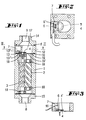
- a housing 1 there are two screw spindles 2, 3 arranged with their screw turns interlock and thereby closed volumes form.
- the spindles run smoothly in ball bearings 18 of the spindle housing mounted.
- the ball bearings 18 are each arranged at the ends of the screw spindles 2, 3.
- One of the two screw spindles 3 carries on her downstream end of an excitation disc 4, which on the bearing end of the spindle is screwed on.
- inlet flange On the inlet side there is an inlet flange on the spindle housing 1 15 mounted, which has an axial inlet opening 8 through which the liquid in the Spindles is pumped in.
- Detector housing part 12 mounted at the opposite end of the spindle housing 1 at the opposite end of the spindle housing 1 at the opposite end of the spindle housing 1 at the opposite end of the spindle housing 1 at the opposite end of the spindle housing 1 is via a seal 10 Detector housing part 12 mounted.
- This detector housing part 12 forms an externally accessible chamber which, via partition walls opposite the measuring chamber 17th is separated.
- outlet flange in the axial direction of the spindle arrangement 14 Connects to the sensor housing 12 an outlet flange in the axial direction of the spindle arrangement 14, which is of the same design as the inlet flange 15 and which forms an outlet opening 9 which is also aligned in the axial direction.
- the aperture 19 Between the housing parts 1 and 12 is in the area of Seal 10 provided an aperture 19 which the bearing 18, which supports one end of the spindle 3, overlaps.
- the aperture 19 has a central opening 19 ', through which the liquid flows out. Through the Opening 19 ' also protrudes a screw which the axle journal forms the disc 4 with which the disc 4th is rotatably connected to the spindle 3.
- the aperture 19 forms the gap wall 13 ′′ of a gap 13, in which rotates the disc 4 about half.
- the opposite Gap wall 13 'of the housing wall formed in the housing 12 retracted sensor chamber 7.
- the chamber wall of the sensor chamber 7 is parallel to disc 4 over the broad side. How in particular 2 can be seen, the magnets 5, which in a uniform circumferential distribution on the disc 4 are arranged, through the gap 13 and run along the chamber wall 13 '.
- the exemplary embodiment there are 2 magnetic field sensors within the chamber 7 6, 6 'arranged side by side.
- the distance between the detectors 6, 6 ' is not equal to the distance the magnet 5 on the disc, so that the phase position the disc and thus the direction of rotation of the disc can be determined.
- the detector chamber 7 has one Cable entry opening for connecting cables for the Hall sensors 6, 6 '.
- the chamber also has a lid 16. With this the chamber after the Assembly of, for example, pre-assembled on a printed circuit board Detectors 6, 6 'are closed in the chamber.
- the disc 4 is in axial extension to the spindle 3 arranged and with a number of discrete magnets Mistake.
- the disc 4 is partially, about half overlapped by the surface 13 'of the detector chamber 7, so that the disc partially rotates in a gap.
- the Disk 5 has a smooth surface and otherwise protrudes into a D-shaped measuring chamber, which is separated from the liquid is flowed through. Becomes a liquid through the screw spindles 2, 3 pumped through, so the spindles 2, 3 set in rotation.
- This too disc 4 rotated in the area of Hall sensors 6, 7 an alternating magnetic field, which is detected by the detectors.
- the detectors then emit a defined pulse signal which is used for Signal processing forwarded via a cable becomes.
- Hall elements 6, 6 ' it is particularly advantageous if the Hall elements 6, 6 ' to assign a separately mountable housing part 12.
- the disc 4 moves in a gap 13, which of two parallel extensions of the Housing part 12 is formed. From two of these Extensions 6, 6 'are formed carriers for detectors, which protrude over the broad side of the disc 4 to to detect the magnets 5 applied there if they dip beneath the detectors 6, 6 '.
Landscapes
- Physics & Mathematics (AREA)
- Fluid Mechanics (AREA)
- General Physics & Mathematics (AREA)
- Measuring Volume Flow (AREA)
- Details Of Garments (AREA)
- Paper (AREA)
- Details Of Flowmeters (AREA)
- Separation Using Semi-Permeable Membranes (AREA)
Applications Claiming Priority (3)
| Application Number | Priority Date | Filing Date | Title |
|---|---|---|---|
| DK121595 | 1995-10-30 | ||
| DK199501215A DK174370B1 (da) | 1995-10-30 | 1995-10-30 | Flowmåler |
| PCT/EP1996/004689 WO1997016706A1 (de) | 1995-10-30 | 1996-10-29 | Durchflussmesser |
Publications (2)
| Publication Number | Publication Date |
|---|---|
| EP0858585A1 EP0858585A1 (de) | 1998-08-19 |
| EP0858585B1 true EP0858585B1 (de) | 2002-01-02 |
Family
ID=8102280
Family Applications (1)
| Application Number | Title | Priority Date | Filing Date |
|---|---|---|---|
| EP96937275A Expired - Lifetime EP0858585B1 (de) | 1995-10-30 | 1996-10-29 | Durchflussmesser |
Country Status (10)
| Country | Link |
|---|---|
| US (1) | US6250151B1 (ja) |
| EP (1) | EP0858585B1 (ja) |
| JP (1) | JP3712738B2 (ja) |
| AT (1) | ATE211541T1 (ja) |
| AU (2) | AU7280296A (ja) |
| BR (1) | BR9611183A (ja) |
| CA (1) | CA2235211A1 (ja) |
| DE (2) | DE59608616D1 (ja) |
| DK (1) | DK174370B1 (ja) |
| WO (2) | WO1997016705A1 (ja) |
Cited By (1)
| Publication number | Priority date | Publication date | Assignee | Title |
|---|---|---|---|---|
| AT519061A1 (de) * | 2016-09-06 | 2018-03-15 | Waizenauer Dietmar | Volumenzähler |
Families Citing this family (36)
| Publication number | Priority date | Publication date | Assignee | Title |
|---|---|---|---|---|
| DE19635435A1 (de) * | 1996-09-02 | 1998-03-05 | Salzkotten Tankanlagen | Flüssigkeitsmeßvorrichtung und -verfahren |
| US6375434B1 (en) * | 2000-02-09 | 2002-04-23 | Tokheim Corporation | Pump/meter combination |
| US20030236489A1 (en) | 2002-06-21 | 2003-12-25 | Baxter International, Inc. | Method and apparatus for closed-loop flow control system |
| US7111520B2 (en) * | 2002-08-26 | 2006-09-26 | Gilbarco Inc. | Increased sensitivity for liquid meter |
| US6882941B2 (en) * | 2002-11-06 | 2005-04-19 | Gilbraco Inc. | Tamper proof meter |
| US6688327B1 (en) | 2002-11-12 | 2004-02-10 | Mark C. Baker | Water meter cover |
| DE102005016374A1 (de) * | 2005-04-09 | 2006-10-12 | Sensitec Gmbh | Messsystem zur Störungserkennung der Rotationsbewegung einer Vorrichtung, wobei die Vorrichtung mindestens einen rotierenden Permanentmagneten aufweist |
| DE102005016373B4 (de) * | 2005-04-09 | 2008-01-31 | SIKA Dr. Siebert & Kühn GmbH & Co. KG | Wasserzähler, umfassend ein Messsystem zur Messung einer Durchflussmenge |
| DE102006005678A1 (de) * | 2006-01-30 | 2007-08-09 | Minol Messtechnik W. Lehmann Gmbh & Co.Kg | Durchflussmessgerät |
| US7546778B2 (en) * | 2007-01-29 | 2009-06-16 | Measurement Specialties, Inc. | Flow meter |
| JP4473328B2 (ja) * | 2008-08-25 | 2010-06-02 | 株式会社オーバル | 軸流式容積流量計 |
| US8069719B2 (en) * | 2009-02-11 | 2011-12-06 | Ecolab Usa Inc. | Gear flow meter with optical sensor |
| AT508805B1 (de) * | 2009-10-09 | 2011-06-15 | Kral Ag | Durchflussmesseinrichtung |
| EP2383547B1 (de) * | 2010-04-30 | 2017-03-22 | Elster GmbH | Fluidzähler |
| EP2383546A1 (de) * | 2010-04-30 | 2011-11-02 | Elster GmbH | Fluidzähler |
| US8166828B2 (en) | 2010-08-06 | 2012-05-01 | Ecolab USA, Inc. | Fluid flow meter |
| DE102010053167A1 (de) | 2010-12-01 | 2012-06-06 | Bischoff Anlagen Gmbh & Co. Kg | Verfahren zur Durchflussmessung |
| DE102010053166A1 (de) | 2010-12-01 | 2012-06-06 | Bischoff Anlagen Gmbh & Co. Kg | Durchflussmesser |
| DE202010016108U1 (de) | 2010-12-01 | 2012-03-02 | Bischoff Anlagen Gmbh & Co. Kg | Durchflussmesser |
| US8757009B2 (en) | 2010-12-08 | 2014-06-24 | Danaher Uk Industries Limited | Fuel dispenser flow meter sensor fraud prevention |
| DE102011011871A1 (de) * | 2011-01-06 | 2012-07-12 | Walter Mehnert | Verfahren und Vorrichtung zur Bestimmung der in einem Verbrauchs-Zeitintervall durch einen Durchflussmengenmesser strömenden Masse eines Fluids |
| US8757010B2 (en) | 2011-04-20 | 2014-06-24 | Gilbarco Inc. | Fuel dispenser flow meter fraud detection and prevention |
| US9817042B2 (en) | 2013-03-14 | 2017-11-14 | Danaher UK Industries, Ltd. | Fuel dispenser tamper detection arrangement |
| WO2014145504A1 (en) | 2013-03-15 | 2014-09-18 | Gilbarco Inc. | Fuel dispenser flow meter fraud detection and prevention |
| WO2015048652A1 (en) | 2013-09-30 | 2015-04-02 | Lincoln Industrial Corporation | Flow measuring device for lubrication systems |
| DE102014115663A1 (de) * | 2014-10-28 | 2016-04-28 | Kem Küppers Elektromechanik Gmbh | Spindeldurchflussmesser |
| US9804016B2 (en) | 2014-10-31 | 2017-10-31 | Gilbarco Inc. | Fuel dispenser flow meter having vapor pressure correction arrangement |
| WO2016070183A1 (en) * | 2014-10-31 | 2016-05-06 | Gilbarco Inc. | Fuel dispenser flow meter having vapor pressure correction arrangement |
| US20160377464A1 (en) * | 2015-06-26 | 2016-12-29 | Atp, Inc. | Flow meter with flow direction sensing, separable fluid path, submersible electronic housing, and wireless communication capacity |
| WO2018013857A1 (en) | 2016-07-13 | 2018-01-18 | Rain Bird Corporation | Flow sensor |
| US11242239B2 (en) | 2017-02-14 | 2022-02-08 | Gilbarco Inc. | Fuel dispenser with fraud resistant flow control valve |
| US10473494B2 (en) | 2017-10-24 | 2019-11-12 | Rain Bird Corporation | Flow sensor |
| IT201800007022A1 (it) * | 2018-07-09 | 2020-01-09 | Misuratore volumetrico di portata. | |
| US11662242B2 (en) | 2018-12-31 | 2023-05-30 | Rain Bird Corporation | Flow sensor gauge |
| US11874149B2 (en) | 2020-04-27 | 2024-01-16 | Rain Bird Corporation | Irrigation flow sensor systems and methods of detecting irrigation flow |
| WO2022093213A1 (en) * | 2020-10-28 | 2022-05-05 | Hewlett-Packard Development Company, L.P. | Printing fluid flow measurement |
Family Cites Families (26)
| Publication number | Priority date | Publication date | Assignee | Title |
|---|---|---|---|---|
| GB1486897A (en) * | 1973-12-11 | 1977-09-28 | Dresser Europe Sa | Fluid flow meter |
| DE2528357C3 (de) * | 1975-05-13 | 1978-03-09 | Langenegger & Liechti, Grosshoechstetten (Schweiz) | Vorrichtung zum Messen der Menge einer strömenden Flüssigkeit mit einem tangential beaufschlagten drehbaren Meßorgan |
| US4224015A (en) * | 1977-01-19 | 1980-09-23 | Oval Engineering Co., Ltd. | Positive displacement flow meter with helical-toothed rotors |
| US4275291A (en) * | 1978-08-21 | 1981-06-23 | Wilgood Corporation | Rotation sensor |
| US4295369A (en) * | 1980-04-10 | 1981-10-20 | Geosource Inc. | Dual magnetic drive for gear meters |
| IT8223718V0 (it) * | 1982-12-15 | 1982-12-15 | Morbi W Gicar Sas | Contatore volumetrico per liquidi. |
| US4641522A (en) * | 1985-04-03 | 1987-02-10 | Lopresti William J | Bearing-less positive displacement flowmeter |
| FR2594221B1 (fr) * | 1986-02-12 | 1988-06-03 | Jaeger | Procede de calibrage d'un debitmetre a roues ovales et debitmetre compense ainsi obtenu |
| US4872352A (en) * | 1986-05-12 | 1989-10-10 | Kevin Alden | Flow meter pulse transmitter |
| US4825707A (en) * | 1986-10-01 | 1989-05-02 | Rosaen Lars O | Fluid flow indicator including a hall effect transducer |
| US4911010A (en) * | 1988-08-12 | 1990-03-27 | Flowdata, Inc. | Fluid flowmeter |
| US4878454A (en) * | 1988-09-16 | 1989-11-07 | Behr Industrial Equipment Inc. | Electrostatic painting apparatus having optically sensed flow meter |
| US5325715A (en) * | 1989-08-09 | 1994-07-05 | Flowdata, Inc. | Fluid flowmeter |
| US4996888A (en) * | 1989-08-09 | 1991-03-05 | Flowdata, Inc. | Fluid flowmeter |
| JPH0670574B2 (ja) * | 1990-03-08 | 1994-09-07 | トキコ株式会社 | 流量計 |
| DE4040409C1 (ja) | 1990-12-18 | 1992-05-14 | Vse Schweisstechnik Gmbh, 5982 Neuenrade, De | |
| DE4042397A1 (de) * | 1990-12-18 | 1992-07-02 | Vse Schweisstechnik Gmbh | Volumensensor fuer fluessigkeiten |
| FR2679648B1 (fr) * | 1991-07-24 | 1996-04-12 | Schlumberger Ind Sa | Transmetteur analogique de position et de sens de rotation. |
| US5251149A (en) * | 1991-08-02 | 1993-10-05 | Great Plains Industries, Inc. | Electronic nutating disc flow meter |
| JPH0536318U (ja) * | 1991-10-18 | 1993-05-18 | トキコ株式会社 | 流量計 |
| DE4142062A1 (de) * | 1991-12-19 | 1993-07-01 | Salzkotten Tankanlagen | Vorrichtung zum messen von fluessigkeitsmengen in zapfsaeulen von kraftfahrzeug-tankstellen |
| DE4208869C2 (de) * | 1992-03-19 | 2001-07-19 | Leistritz Ag | Volumetrischer Kraftstoff-Durchflußmesser |
| JP3063809B2 (ja) * | 1992-11-19 | 2000-07-12 | トキコ株式会社 | 容積流量計 |
| DE4423461A1 (de) | 1994-07-05 | 1996-01-11 | Leistritz Ag | Volumeter |
| DE4429311C2 (de) * | 1994-08-18 | 1998-05-20 | Daimler Benz Ag | Prüfeinrichtung für Fahrzeuge mit magnetfeldsensitivem Raddrehzahlsensor |
| DE4442193A1 (de) * | 1994-11-15 | 1996-05-23 | Allmess Schlumberger Gmbh | Elektronisches Zählwerksmodul für einen Wasserzähler |
-
1995
- 1995-10-30 DK DK199501215A patent/DK174370B1/da not_active IP Right Cessation
-
1996
- 1996-10-28 WO PCT/DK1996/000447 patent/WO1997016705A1/en active Application Filing
- 1996-10-28 AU AU72802/96A patent/AU7280296A/en not_active Abandoned
- 1996-10-29 BR BR9611183-6A patent/BR9611183A/pt not_active IP Right Cessation
- 1996-10-29 CA CA002235211A patent/CA2235211A1/en not_active Abandoned
- 1996-10-29 DE DE59608616T patent/DE59608616D1/de not_active Expired - Lifetime
- 1996-10-29 WO PCT/EP1996/004689 patent/WO1997016706A1/de active IP Right Grant
- 1996-10-29 JP JP51705997A patent/JP3712738B2/ja not_active Expired - Fee Related
- 1996-10-29 AU AU74947/96A patent/AU716668B2/en not_active Ceased
- 1996-10-29 EP EP96937275A patent/EP0858585B1/de not_active Expired - Lifetime
- 1996-10-29 DE DE19680873T patent/DE19680873D2/de not_active Expired - Lifetime
- 1996-10-29 AT AT96937275T patent/ATE211541T1/de not_active IP Right Cessation
- 1996-12-29 US US09/077,741 patent/US6250151B1/en not_active Expired - Lifetime
Cited By (2)
| Publication number | Priority date | Publication date | Assignee | Title |
|---|---|---|---|---|
| AT519061A1 (de) * | 2016-09-06 | 2018-03-15 | Waizenauer Dietmar | Volumenzähler |
| AT519061B1 (de) * | 2016-09-06 | 2018-05-15 | Nexus Automation Gmbh | Volumenzähler |
Also Published As
| Publication number | Publication date |
|---|---|
| WO1997016705A1 (en) | 1997-05-09 |
| DK121595A (da) | 1997-05-01 |
| AU7280296A (en) | 1997-05-22 |
| DE19680873D2 (de) | 1999-01-28 |
| CA2235211A1 (en) | 1997-05-09 |
| JP3712738B2 (ja) | 2005-11-02 |
| DE59608616D1 (de) | 2002-02-28 |
| ATE211541T1 (de) | 2002-01-15 |
| DK174370B1 (da) | 2003-01-13 |
| AU716668B2 (en) | 2000-03-02 |
| JPH11514739A (ja) | 1999-12-14 |
| WO1997016706A1 (de) | 1997-05-09 |
| EP0858585A1 (de) | 1998-08-19 |
| AU7494796A (en) | 1997-05-22 |
| US6250151B1 (en) | 2001-06-26 |
| BR9611183A (pt) | 1999-12-28 |
Similar Documents
| Publication | Publication Date | Title |
|---|---|---|
| EP0858585B1 (de) | Durchflussmesser | |
| EP1464935B1 (de) | Vorrichtung zum Bestimmen eines auf eine Welle ausgeübten Drehmoments | |
| DE3935261A1 (de) | Mehrfachumdrehungswellen-positionssensor mit spielkompensation | |
| EP2743662B1 (de) | Vorrichtung mit einer Drehmomentsensoreinrichtung und optional einer Lenkwinkelsensoreinrichtung für ein Kraftfahrzeug | |
| DE4213866B4 (de) | Sensor für Drehbewegungen | |
| EP3250890B1 (de) | Magnet-basiertes drehwinkelmesssystem | |
| EP1751505B1 (de) | Durchflussmengenfühler | |
| EP0660263A1 (de) | Mehrstelliges Rollenzählwerk für ein Volumenmessgerät | |
| DE102009031176A1 (de) | Winkelsensor | |
| DE10133542A1 (de) | Drehwinkelsensor | |
| DE102006055049B3 (de) | Kombinierter Lenkwinkel- und Drehmomentsensor | |
| DE102015101248A1 (de) | Magnet-basiertes Drehwinkelmesssystem | |
| DE4331909A1 (de) | Drehwinkelgeber | |
| EP2101157A2 (de) | Magnetischer Drehwinkelsensor | |
| DE4118773C2 (de) | Positionsdetektor | |
| EP3171137B1 (de) | Drehgeberanordnung | |
| DE4042397C2 (ja) | ||
| EP0836072B1 (de) | Drehgeber | |
| DE2943184A1 (de) | Durchflussmesszelle | |
| DE19852915A1 (de) | Meßvorrichtung zur berührungslosen Erfassung eines Drehwinkels | |
| DE10201141B4 (de) | Stellgetriebe mit Einrichtungen zur Feststellung der Abweichung von einer vorgegebenen Ausgangsstellung | |
| WO2011144313A1 (de) | Magnetfeldsensor für einen positionsgeber | |
| EP3936828B1 (de) | Gebersystem für einen antrieb | |
| DE102004009839A1 (de) | Drehwinkelsensor | |
| EP1210572B1 (de) | Drehwinkel mit mikrostreifenleiterresonatoren ( 2,4 ghz, 2 grad ) |
Legal Events
| Date | Code | Title | Description |
|---|---|---|---|
| PUAI | Public reference made under article 153(3) epc to a published international application that has entered the european phase |
Free format text: ORIGINAL CODE: 0009012 |
|
| 17P | Request for examination filed |
Effective date: 19980424 |
|
| AK | Designated contracting states |
Kind code of ref document: A1 Designated state(s): AT BE CH DE DK ES FI FR GB IE IT LI LU NL PT SE |
|
| RAP1 | Party data changed (applicant data changed or rights of an application transferred) |
Owner name: MARCONI COMMERCE SYSTEMS GMBH & CO.KG |
|
| 17Q | First examination report despatched |
Effective date: 20000721 |
|
| GRAG | Despatch of communication of intention to grant |
Free format text: ORIGINAL CODE: EPIDOS AGRA |
|
| GRAG | Despatch of communication of intention to grant |
Free format text: ORIGINAL CODE: EPIDOS AGRA |
|
| GRAH | Despatch of communication of intention to grant a patent |
Free format text: ORIGINAL CODE: EPIDOS IGRA |
|
| GRAH | Despatch of communication of intention to grant a patent |
Free format text: ORIGINAL CODE: EPIDOS IGRA |
|
| GRAA | (expected) grant |
Free format text: ORIGINAL CODE: 0009210 |
|
| REG | Reference to a national code |
Ref country code: GB Ref legal event code: IF02 |
|
| AK | Designated contracting states |
Kind code of ref document: B1 Designated state(s): AT BE CH DE DK ES FI FR GB IE IT LI LU NL PT SE |
|
| PG25 | Lapsed in a contracting state [announced via postgrant information from national office to epo] |
Ref country code: IE Free format text: LAPSE BECAUSE OF FAILURE TO SUBMIT A TRANSLATION OF THE DESCRIPTION OR TO PAY THE FEE WITHIN THE PRESCRIBED TIME-LIMIT Effective date: 20020102 Ref country code: FI Free format text: LAPSE BECAUSE OF FAILURE TO SUBMIT A TRANSLATION OF THE DESCRIPTION OR TO PAY THE FEE WITHIN THE PRESCRIBED TIME-LIMIT Effective date: 20020102 |
|
| REF | Corresponds to: |
Ref document number: 211541 Country of ref document: AT Date of ref document: 20020115 Kind code of ref document: T |
|
| RIN1 | Information on inventor provided before grant (corrected) |
Inventor name: HARDING,ALFONS Inventor name: KOELP, MANFRED Inventor name: MILLER, WILLI Inventor name: TINGLEFF, MICHAEL |
|
| REG | Reference to a national code |
Ref country code: CH Ref legal event code: EP |
|
| GBT | Gb: translation of ep patent filed (gb section 77(6)(a)/1977) |
Effective date: 20020102 |
|
| REG | Reference to a national code |
Ref country code: IE Ref legal event code: FG4D Free format text: GERMAN |
|
| REF | Corresponds to: |
Ref document number: 59608616 Country of ref document: DE Date of ref document: 20020228 |
|
| PG25 | Lapsed in a contracting state [announced via postgrant information from national office to epo] |
Ref country code: SE Free format text: LAPSE BECAUSE OF FAILURE TO SUBMIT A TRANSLATION OF THE DESCRIPTION OR TO PAY THE FEE WITHIN THE PRESCRIBED TIME-LIMIT Effective date: 20020402 Ref country code: PT Free format text: LAPSE BECAUSE OF FAILURE TO SUBMIT A TRANSLATION OF THE DESCRIPTION OR TO PAY THE FEE WITHIN THE PRESCRIBED TIME-LIMIT Effective date: 20020402 Ref country code: DK Free format text: LAPSE BECAUSE OF FAILURE TO SUBMIT A TRANSLATION OF THE DESCRIPTION OR TO PAY THE FEE WITHIN THE PRESCRIBED TIME-LIMIT Effective date: 20020402 |
|
| ET | Fr: translation filed | ||
| PG25 | Lapsed in a contracting state [announced via postgrant information from national office to epo] |
Ref country code: ES Free format text: LAPSE BECAUSE OF FAILURE TO SUBMIT A TRANSLATION OF THE DESCRIPTION OR TO PAY THE FEE WITHIN THE PRESCRIBED TIME-LIMIT Effective date: 20020730 |
|
| REG | Reference to a national code |
Ref country code: IE Ref legal event code: FD4D |
|
| PG25 | Lapsed in a contracting state [announced via postgrant information from national office to epo] |
Ref country code: LU Free format text: LAPSE BECAUSE OF NON-PAYMENT OF DUE FEES Effective date: 20021029 Ref country code: AT Free format text: LAPSE BECAUSE OF NON-PAYMENT OF DUE FEES Effective date: 20021029 |
|
| PG25 | Lapsed in a contracting state [announced via postgrant information from national office to epo] |
Ref country code: LI Free format text: LAPSE BECAUSE OF NON-PAYMENT OF DUE FEES Effective date: 20021031 Ref country code: CH Free format text: LAPSE BECAUSE OF NON-PAYMENT OF DUE FEES Effective date: 20021031 |
|
| PGFP | Annual fee paid to national office [announced via postgrant information from national office to epo] |
Ref country code: NL Payment date: 20021031 Year of fee payment: 7 |
|
| PLBE | No opposition filed within time limit |
Free format text: ORIGINAL CODE: 0009261 |
|
| STAA | Information on the status of an ep patent application or granted ep patent |
Free format text: STATUS: NO OPPOSITION FILED WITHIN TIME LIMIT |
|
| 26N | No opposition filed | ||
| REG | Reference to a national code |
Ref country code: CH Ref legal event code: PL |
|
| PGFP | Annual fee paid to national office [announced via postgrant information from national office to epo] |
Ref country code: BE Payment date: 20031211 Year of fee payment: 8 |
|
| PG25 | Lapsed in a contracting state [announced via postgrant information from national office to epo] |
Ref country code: NL Free format text: LAPSE BECAUSE OF NON-PAYMENT OF DUE FEES Effective date: 20040501 |
|
| NLV4 | Nl: lapsed or anulled due to non-payment of the annual fee |
Effective date: 20040501 |
|
| PG25 | Lapsed in a contracting state [announced via postgrant information from national office to epo] |
Ref country code: BE Free format text: LAPSE BECAUSE OF NON-PAYMENT OF DUE FEES Effective date: 20041031 |
|
| BERE | Be: lapsed |
Owner name: *MARCONI COMMERCE SYSTEMS G.M.B.H. & CO. K.G. Effective date: 20041031 |
|
| PGFP | Annual fee paid to national office [announced via postgrant information from national office to epo] |
Ref country code: GB Payment date: 20061025 Year of fee payment: 11 |
|
| PGFP | Annual fee paid to national office [announced via postgrant information from national office to epo] |
Ref country code: IT Payment date: 20061031 Year of fee payment: 11 |
|
| BERE | Be: lapsed |
Owner name: *MARCONI COMMERCE SYSTEMS G.M.B.H. & CO. K.G. Effective date: 20041031 |
|
| GBPC | Gb: european patent ceased through non-payment of renewal fee |
Effective date: 20071029 |
|
| REG | Reference to a national code |
Ref country code: FR Ref legal event code: ST Effective date: 20080630 |
|
| PGFP | Annual fee paid to national office [announced via postgrant information from national office to epo] |
Ref country code: FR Payment date: 20061010 Year of fee payment: 11 |
|
| PG25 | Lapsed in a contracting state [announced via postgrant information from national office to epo] |
Ref country code: GB Free format text: LAPSE BECAUSE OF NON-PAYMENT OF DUE FEES Effective date: 20071029 |
|
| PG25 | Lapsed in a contracting state [announced via postgrant information from national office to epo] |
Ref country code: FR Free format text: LAPSE BECAUSE OF NON-PAYMENT OF DUE FEES Effective date: 20071031 |
|
| PG25 | Lapsed in a contracting state [announced via postgrant information from national office to epo] |
Ref country code: IT Free format text: LAPSE BECAUSE OF NON-PAYMENT OF DUE FEES Effective date: 20071029 |
|
| PGFP | Annual fee paid to national office [announced via postgrant information from national office to epo] |
Ref country code: DE Payment date: 20150930 Year of fee payment: 20 |
|
| REG | Reference to a national code |
Ref country code: DE Ref legal event code: R071 Ref document number: 59608616 Country of ref document: DE |