EP0857990B1 - Rotating laser beam irradiating apparatus - Google Patents
Rotating laser beam irradiating apparatus Download PDFInfo
- Publication number
- EP0857990B1 EP0857990B1 EP98102092A EP98102092A EP0857990B1 EP 0857990 B1 EP0857990 B1 EP 0857990B1 EP 98102092 A EP98102092 A EP 98102092A EP 98102092 A EP98102092 A EP 98102092A EP 0857990 B1 EP0857990 B1 EP 0857990B1
- Authority
- EP
- European Patent Office
- Prior art keywords
- pulse
- laser
- laser beam
- rotating
- irradiating
- Prior art date
- Legal status (The legal status is an assumption and is not a legal conclusion. Google has not performed a legal analysis and makes no representation as to the accuracy of the status listed.)
- Expired - Lifetime
Links
- 230000001678 irradiating effect Effects 0.000 title claims description 49
- 230000003287 optical effect Effects 0.000 claims description 20
- 239000013078 crystal Substances 0.000 claims description 9
- 238000005086 pumping Methods 0.000 claims description 4
- 238000001514 detection method Methods 0.000 claims description 2
- 238000010586 diagram Methods 0.000 description 25
- 239000004065 semiconductor Substances 0.000 description 13
- 230000005684 electric field Effects 0.000 description 5
- 238000000034 method Methods 0.000 description 5
- 230000000007 visual effect Effects 0.000 description 5
- 230000007423 decrease Effects 0.000 description 4
- 238000010276 construction Methods 0.000 description 3
- 230000000694 effects Effects 0.000 description 3
- 230000010287 polarization Effects 0.000 description 3
- JNDMLEXHDPKVFC-UHFFFAOYSA-N aluminum;oxygen(2-);yttrium(3+) Chemical compound [O-2].[O-2].[O-2].[Al+3].[Y+3] JNDMLEXHDPKVFC-UHFFFAOYSA-N 0.000 description 2
- 229910019901 yttrium aluminum garnet Inorganic materials 0.000 description 2
- 230000008859 change Effects 0.000 description 1
- 230000001427 coherent effect Effects 0.000 description 1
- 239000012141 concentrate Substances 0.000 description 1
- 230000008878 coupling Effects 0.000 description 1
- 238000010168 coupling process Methods 0.000 description 1
- 238000005859 coupling reaction Methods 0.000 description 1
- 238000000605 extraction Methods 0.000 description 1
- 150000002500 ions Chemical class 0.000 description 1
- 230000008569 process Effects 0.000 description 1
- 230000004044 response Effects 0.000 description 1
- 230000003595 spectral effect Effects 0.000 description 1
- 239000000126 substance Substances 0.000 description 1
Images


Classifications
-
- G—PHYSICS
- G02—OPTICS
- G02B—OPTICAL ELEMENTS, SYSTEMS OR APPARATUS
- G02B26/00—Optical devices or arrangements for the control of light using movable or deformable optical elements
- G02B26/08—Optical devices or arrangements for the control of light using movable or deformable optical elements for controlling the direction of light
- G02B26/10—Scanning systems
Definitions
- the present invention relates to a rotating laser beam irradiating apparatus, and more particularly to a rotating laser beam irradiating apparatus which, by synchronizing an emission timing of a pulse laser with a rotation of an irradiating means, makes it possible to describe intermittent dot-shaped marks, to tremendously increase a visual recognition distance, and to enlarge a work area.
- a red-colored laser diode reflecting recent technological advances in a semiconductor laser, is employed in the rotating laser beam irradiating apparatus for forming the rotating laser beam plane.
- the rotating laser beam irradiating apparatus using the red-colored laser diode is battery-operable and easy to handle, thus being widely used in a construction work area.
- a prior art rotating laser beam irradiating apparatus comprises a laser light projector and a laser light irradiating unit which rotates around an optical axis of the laser light projector so as to irradiate with a laser light deflected by 90 degrees to the optical axis of the laser light projector.
- the prior art rotating laser beam irradiating apparatus by rotating the laser light irradiating unit, makes it possible to form the reference plane or to provide a reference line on an object such as a wall surface.
- the prior art rotating laser beam irradiating apparatus using the red-colored laser diode had a limit in an output of the semiconductor laser, and in addition had a restriction to an irradiating output of the laser in order to assure safety for the eyes of a worker. This resulted in a problem that, in a comparatively bright work area and at a position a little away from the rotating laser beam irradiating apparatus, it becomes impossible to visually recognize the rotating laser beam plane.
- employed as a means for generating the green laser can be a solid-state laser generating apparatus using a secondary higher harmonics generator being widespread in recent years.
- the solid-state laser generating apparatus is able to generate a comparatively high output of green laser, but the power consumption thereof was great and the generating apparatus was found to be difficult to drive continuously for a long time by the battery-operation.
- the present invention relates to a rotating laser beam irradiating apparatus as defined in claim 1.
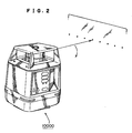
- Fig. 1 shows a configuration of a rotating laser beam irradiating apparatus 10000 according to the present embodiment
- Fig. 2 shows a perspective view of the rotating laser beam irradiating apparatus 10000.
- Described below is an optical and electrical configuration of the rotating laser beam irradiating apparatus 10000.
- the rotating laser beam irradiating apparatus 10000 comprises a light emitting unit 115, a rotating unit 116, a control unit (CPU) 118, a laser driving unit 119, a motor driving unit 120, and a display unit 121.
- the control unit (CPU) 118 corresponds to the arithmetic processing means.
- the light emitting unit 115 is configured by a laser beam emitting apparatus 1000 and a collimator lens 126.
- a laser light launched out from the laser beam emitting apparatus 1000 is converted into a collimated light beam by the collimator lens 126, and the collimated light beam is launched into the rotating unit 116 situated upwards.
- the laser beam emitting apparatus 1000 corresponds to the pulse laser light source.
- the rotating unit 116 is a unit for scanning the laser light introduced from the light emitting unit 115 so as to deflect the laser light by 90 degrees and for launching out the deflected laser light.
- The comprises a penta prism 114, a rotation supporter 13, a driving gear 16, a driven gear 17, a scanning motor 15, and an encoder 129. Also, the rotating unit 116 corresponds to the irradiating means.
- the penta prism 114 is a unit for deflecting by 90 degrees the laser light introduced from the light emitting unit 115.
- the penta prism 114 by reflecting the laser light twice inside the penta prism 114, enables the laser light to be deflected by 90 degrees.
- the rotation supporter 13 is a unit for rotating the penta prism 114, and is provided with the driven gear 17.
- the rotation supporter 13 is able to rotate and scan, in a substantially horizontal direction, the laser light introduced from the light emitting unit 115.
- the scanning motor 15 is a driving source for rotating the penta prism 114 through the rotation supporter 13. Formed on the scanning motor 15 is the driving gear 16. The driving gear 16 is engaged with the driven gear 17, and a rotating driving force by the driving gear 16 is transmitted to the driven gear 17, thus making it possible to rotate the penta prism 114 through the rotation supporter 13. Additionally, the scanning motor 15, the driving gear 16, and the driven gear 17 correspond to the rotation driving means.
- an encoder 129 is attached to the rotation supporter 13, thus making it possible to detect a state in which the rotation supporter 13 is rotating.
- a detection signal from the encoder 129 is configured to be inputted into the control unit 118.
- the encoder 129 corresponds to the rotation detecting means, and in the present embodiment, the encoder 129 is able to detect an irradiating direction of a laser light, too.
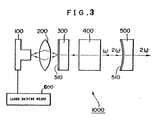
- Fig. 3 shows a laser beam emitting apparatus 1000 according to the present embodiment, which comprises a laser light source 100, a condenser lens 200, a laser crystal 300, a non-linear optical medium 400, an output mirror 500 and a laser driving means 600.
- the laser light source 100 is used to generate a laser beam.
- a semiconductor laser is used as the laser light source 100.
- the laser light source 100 functions as a pumping light generator for generating a fundamental wave.
- the laser driving means 600 is used to drive the laser light source 100.
- the laser driving means 600 is capable of pulse-driving the laser light source 100.
- the laser crystal 300 is a medium having a negative temperature and is used to amplify light.
- YAG Yttrium Aluminum Garnet
- Nd 3+ ions, or the like is adopted as the laser crystal 300.
- a first dielectric reflecting film 310 is formed on the laser light source 100 side of the laser crystal 300.
- the output mirror 500 is configured so as to be opposed to the laser crystal 300 with the first dielectric reflecting film 310 formed thereon.
- the laser crystal 300 side of the output mirror 500 is processed into a shape of a concave spherical mirror having a suitable radius so that a second dielectric reflecting film 510 is formed on the output mirror 500.
- the non-linear optical medium 400 is inserted into an optical resonator composed of the first dielectric reflecting film 310 of the laser crystal 300 and the output mirror 500.
- Coupling occurs between optical waves having frequencies different from each other due to the non-linear polarized component, so that harmonics doubling the frequency of the optical wave are produced.
- the non-linear optical medium 400 is inserted into the optical resonator composed of the laser crystal 300 and the output mirror 500, it is called "internal type SHG". Since a converted output is proportional to the square of optical power of the fundamental wave, an effect can be brought about in that a large optical intensity in the optical resonator can be directly used.
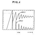
- Fig. 4 shows the relationship between an inverted population and the intensity of light at the time of relaxation vibrations of a commonly-used laser light source.
- a delta N(t) shown in Fig. 4 indicates the inverted population (gain), ⁇ (t) indicates the intensity of light, and the abscissa indicates the elapse of time.
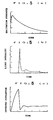
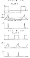
- Figs. 5(a), 5(b) and 5(c) typically show gain switches, respectively, wherein Fig. 5 (a) is a diagram showing the relationship between the time and the intensity of pumping, Fig. 5(b) is a diagram showing the relationship between the time and the intensity of light, and Fig. 5(c) is a diagram illustrating the relationship between the time and the inverted population.
- the maximum light intensity is produced in response to the first pulse. Thereafter, since the light intensity is reduced so as to converge on a predetermined light intensity, the use of the first pulse alone allows the most efficient extraction of light.
- a drive pulse for driving the semiconductor laser and an optical pulse outputted from the semiconductor laser are substantially identical in period and pulse width to each other.
- Fig. 6 (a) is a diagram showing the relationship in which a period T of the continuous pulse supplied to the semiconductor laser satisfies the condition that ⁇ FL ⁇ T - ⁇ .
- ⁇ FL indicates the life of fluorescence
- ⁇ indicates the width of the pulse.
- Fig. 10(b) is a diagram showing the relationship in which the period T of the continuous pulse supplied to the semiconductor laser satisfies the condition that ⁇ FL > T - ⁇ .
- the quantity of light emitted from the laser beam emitting apparatus 1000 increases nonlinearly.
- the peak value of the input pulse current supplied to the laser light source 100 is defined as a rated value of the laser light source 100 and the duty ratio and period of the input pulse are controlled, then the quantity of a laser beam or light can be varied in a state in which the laser has been oscillated with most efficiency.
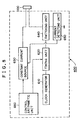
- the laser driving means 600 employed in the present embodiment will next be described in detail based on Fig. 8.
- the laser driving means 600 comprises a clock generator 610, a timing unit 620, a constant current source 630, a switching unit 640, a current detecting unit 650 and a control arithmetic unit 660.
- the clock generator 610 is an oscillator for generating a clock used as the reference.
- the timing unit 620 is used to set the time and period required for the laser light source 100 to emit light, based on the reference clock generated from the clock generator 610.
- the constant current source 630 is used to supply a rated current to the laser light source 100 and to set a current used up by the laser light source 100, which is detected by the current detecting unit 650, to the rated current at all times.
- the switching unit 640 is used to switch the current supplied to the laser light source 100 by switching, based on a signal outputted from the timing unit 620.
- the current detecting unit 650 is used to detect a current flowing in the laser light source 100. Any current detecting means may by adopted if ones capable of detecting the current flowing in the laser light source 100 are used.
- the control arithmetic unit 660 is used to send a control signal to the timing unit 620 and the constant current source 630 and thereby supply a desired drive signal to the laser light source 100.
- the laser driving means 600 of the laser beam emitting apparatus 1000 according to the present embodiment constructed as described above can form a drive signal to be sent to the laser light source 100, based on the control signal outputted from the control arithmetic unit 660.
- the drive signal produced by the laser driving means 600 will next be described in detail.
- a first drive signal is used to control and drive the laser light source 100 under the control of the period of a pulse thereof to thereby adjust the quantity of light emitted from the laser beam emitting apparatus 1000.
- Figs.9 (a) and 9 (b) respectively show a first drive signal produced by the laser driving means 600.
- the period of the pulse thereof is varied. Namely, when it is desired to increase the quality of light emitted from the laser beam emitting apparatus 1000, the cycle or period of the pulse thereof is rendered short and an effective value of the drive signal supplied to the laser light source 100 is increased, as shown in Fig.9 (a). As a result, the quantity of light emitted from the laser beam emitting apparatus 1000 increases.
- the period of the pulse of the drive signal is rendered long and the effective value of the drive signal supplied to the laser light source 100 is reduced, as shown in Fig. 9(b). As a result, the quantity of light emitted from the laser beam emitting apparatus 1000 is decrease.
- the laser driving means 600 can change the drive signal supplied to the laser light source 100 to adjust the quantity of light emitted from the laser beam emitting apparatus 1000.
- the period of the pulse of the first drive signal is a few 100 KHz but may suitably be set.
- a second drive signal is used to control and drive the laser light source 100 under the control of the duty ratio of a pulse thereof to thereby adjust the quantity of light emitted from the laser beam emitting apparatus 1000.
- Fig.10 (a) and 10(b) respectively show a second drive signal formed by the laser driving means 600, in which the duty ratio of a pulse thereof is varied in a state in which the cycle or period of the pulse remains unchanged. Namely, the duty ratio corresponding to the ratio between a time (T 1 ) required to hold ON the drive signal supplied to the laser light source 100 and a time (T 2 ) required to hold OFF the drive signal is changed.
- the laser driving means 600 changes the time required to drive the drive signal supplied to the laser light source 100 to vary the duty ratio of the pulse thereof, thereby making it possible to adjust the quantity of light emitted from the laser beam emitting apparatus 1000.
- the period of the pulse of the second drive signal is a few 100 KHz but may suitably be set.
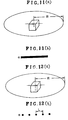
- Figs. 11(a) and 11(b) show laser beam emitting apparatus not whithin the scope of the invention which generates a continuous laser light beam, and a rotating laser beam plane is formed by launching out the laser light beam being rotated at the same time.
- a band-shaped line turns out to be drawn.
- the band-shaped line in Fig. 11(b) means that the energy of the laser light is dispersed in a band-shaped manner in terms of time from the laser beam irradiating apparatus 10000, and as the distance R increases, the brightness of the band-shaped line decreases.
- Figs. 12(a) and 12(b) show the principle of the present invention.
- a cross section of the light beam is projected for every spacing L, and dot-shaped marks turn out to be drawn.
- the dot-shaped marks in Fig. 12(b) mean that the energy of the laser light is concentrated in a dot-shaped manner from the laser beam irradiating apparatus 10000, and even if the optical energy is equal, it is possible to draw a dot-shaped intermittent line with a high luminance.
- the energy dispersed on a line L in length is concentrated in a dot-shaped manner. This, even if the average output is equal, makes it possible to draw the dot-shaped intermittent line with a high luminance, thus tremendously increasing the visual recognition distance.
- the spacing L between two of the dot-shaped marks become longer as the distance R, which is a distance from the laser beam irradiating apparatus to the irradiation position such as a wall, gets longer.
- the brightness of the dot-shaped marks turns out to be equal regardless of the distance R, thus eventually enabling the visual recognition distance to be lengthened.
- the condition needs to be T p-on ⁇ ⁇ / (R* ⁇ ), assuming that, as shown in Fig. 13, the light beam moves by a length of the diameter of the light beam during the emitting period, where T p-on designates an emitting time width of the pulse laser from the laser beam irradiating apparatus 10000, ⁇ (omega) designates an angular velocity (rad/s), ⁇ designates a cross section diameter of the light beam, and R designates a distance between the laser beam irradiating apparatus 10000 and an irradiated object.
- T p-on 1 or less ⁇ s.
- a condition for allowing the marks to look intermittent, not continuous needs to be ⁇ / (R* ⁇ ) ⁇ T p-off , where T p-off designates an extinguishing time of the pulse laser.
- the encoder 129 detects an angular velocity ⁇ of the rotation supporter 13, thus inputting the data on the angular velocity into the control unit 118.
- T p-on-off 2 * ⁇ * (m/n) (both m and n are integer), where T p-on-off designates an emitting time interval of the pulse laser.
- the control unit 118 controls the angular velocity ⁇ of the rotation supporter 13 so as to satisfy this condition. Namely, the control unit 118 controls and drives the scanning motor 15 through the motor controlling unit 120, thus performing PPL (PHASE LOCK LOOP) control so that the angular velocity of the rotation supporter 13 coincides with ⁇ .
- PPL PASE LOCK LOOP
- the control unit 118 by controlling the motor controlling unit 120, makes it possible to synchronize an emission timing of the pulse laser with the rotation of the rotating unit 116, thus describing intermittent dot-shaped marks.
- the shape of the mark is not limited to the shape illustrated in Fig. 13, and can be varied by changing the angular velocity w and the emitting time width of the pulse laser T p-on , depending on the situation and requirements as shown in Fig. 14.
- the spacing between the dot-shaped marks can be modified approximately by varying the angular velocity ⁇ and the emitting time interval of the pulse laser T p-on-off .
- the present invention makes it possible to concentrate dispersed optical energy in a dot-shaped manner, and, even if the average output is equal, makes it possible to draw a dot-shaped intermittent line with a high luminance, thus resulting in an effect of tremendously increasing the visual recognition distance.
- the period T of the driving pulse by the pulse driving means satisfies a condition ⁇ FL > T - ⁇ for ⁇ FL (life of fluorescence). This makes it possible to pump the optical resonator using a maximum intensity of laser light based on the first pulse, thus bringing about an effect of emitting a laser light with high efficiency.
Landscapes
- Physics & Mathematics (AREA)
- General Physics & Mathematics (AREA)
- Optics & Photonics (AREA)
- Semiconductor Lasers (AREA)
- Lasers (AREA)
- Laser Beam Processing (AREA)
Applications Claiming Priority (3)
| Application Number | Priority Date | Filing Date | Title |
|---|---|---|---|
| JP04015397A JP3757344B2 (ja) | 1997-02-09 | 1997-02-09 | 回転レーザー照射装置 |
| JP4015397 | 1997-02-09 | ||
| JP40153/97 | 1997-02-09 |
Publications (3)
| Publication Number | Publication Date |
|---|---|
| EP0857990A2 EP0857990A2 (en) | 1998-08-12 |
| EP0857990A3 EP0857990A3 (en) | 1999-06-30 |
| EP0857990B1 true EP0857990B1 (en) | 2005-12-28 |
Family
ID=12572831
Family Applications (1)
| Application Number | Title | Priority Date | Filing Date |
|---|---|---|---|
| EP98102092A Expired - Lifetime EP0857990B1 (en) | 1997-02-09 | 1998-02-06 | Rotating laser beam irradiating apparatus |
Country Status (4)
| Country | Link |
|---|---|
| US (1) | US5909455A (enExample) |
| EP (1) | EP0857990B1 (enExample) |
| JP (1) | JP3757344B2 (enExample) |
| DE (1) | DE69832915T2 (enExample) |
Families Citing this family (12)
| Publication number | Priority date | Publication date | Assignee | Title |
|---|---|---|---|---|
| US6144659A (en) * | 1996-12-19 | 2000-11-07 | Lucent Technologies Inc. | Telecommunication equipment support of high speed data services |
| US6195385B1 (en) * | 1998-06-30 | 2001-02-27 | Cisco Systems, Inc. | HTU-C clocking from a single source |
| US7266897B2 (en) * | 2004-06-21 | 2007-09-11 | Laserline Mfg., Inc. | Self-aligning, self plumbing baseline instrument |
| JP2010033679A (ja) * | 2008-07-30 | 2010-02-12 | Sony Corp | 光情報記録装置、光ピックアップ及びレーザ光出射方法 |
| JP5332462B2 (ja) * | 2008-09-29 | 2013-11-06 | ソニー株式会社 | 短パルス光源、レーザ光出射方法、光学装置、光ディスク装置及び光ピックアップ |
| JP5338234B2 (ja) | 2008-09-30 | 2013-11-13 | ソニー株式会社 | 短パルス光源、レーザ光出射方法、光学装置、光ディスク装置及び光ピックアップ |
| KR20110056257A (ko) | 2008-10-03 | 2011-05-26 | 소니 주식회사 | 광 픽업, 광 정보 기록 방법 및 광 디스크 장치 |
| JP5693827B2 (ja) * | 2009-06-17 | 2015-04-01 | 株式会社トプコン | 測量システム |
| US8684632B2 (en) | 2010-12-08 | 2014-04-01 | Laserline Mfg., Inc. | Systems and methods for laying out and installing a solar panel array |
| JP2011187157A (ja) * | 2011-05-06 | 2011-09-22 | Sony Corp | レーザ光照射装置及びレーザ光照射方法。 |
| WO2020051784A1 (en) * | 2018-09-12 | 2020-03-19 | Robert Bosch Gmbh | Laser leveling tool with improved laser pattern projection |
| CN113701729A (zh) * | 2021-08-03 | 2021-11-26 | 常州工学院 | 一种激光扫平仪系统 |
Family Cites Families (10)
| Publication number | Priority date | Publication date | Assignee | Title |
|---|---|---|---|---|
| JPS5350594A (en) * | 1976-10-19 | 1978-05-09 | Matsushita Electric Ind Co Ltd | Apparatus for correcting dynamic unbalance of rotary body |
| US4830489A (en) * | 1986-08-20 | 1989-05-16 | Spectra-Physics, Inc. | Three dimensional laser beam survey system |
| US5121160A (en) * | 1989-03-09 | 1992-06-09 | Canon Kabushiki Kaisha | Exposure method and apparatus |
| EP0429012B1 (en) * | 1989-11-17 | 1995-02-01 | Kabushiki Kaisha TOPCON | Laser beam controller for surveying equipment |
| JPH04345078A (ja) * | 1991-05-22 | 1992-12-01 | Sony Corp | レーザ光発生装置 |
| JP3190746B2 (ja) * | 1992-10-29 | 2001-07-23 | 株式会社トプコン | レーザポインタ |
| JPH08159768A (ja) * | 1994-12-01 | 1996-06-21 | Asahi Optical Co Ltd | レーザ測量装置 |
| US5819424A (en) * | 1995-01-11 | 1998-10-13 | Kabushiki Kaisha Topcon | Laser leveling device |
| JP3684248B2 (ja) * | 1995-01-11 | 2005-08-17 | 株式会社トプコン | レーザ回転照射装置 |
| EP0743726B1 (en) * | 1995-05-19 | 1999-09-01 | Kabushiki Kaisha Topcon | Laser oscillating apparatus |
-
1997
- 1997-02-09 JP JP04015397A patent/JP3757344B2/ja not_active Expired - Fee Related
-
1998
- 1998-02-05 US US09/019,285 patent/US5909455A/en not_active Expired - Lifetime
- 1998-02-06 EP EP98102092A patent/EP0857990B1/en not_active Expired - Lifetime
- 1998-02-06 DE DE69832915T patent/DE69832915T2/de not_active Expired - Lifetime
Also Published As
| Publication number | Publication date |
|---|---|
| JPH10221075A (ja) | 1998-08-21 |
| DE69832915D1 (de) | 2006-02-02 |
| EP0857990A2 (en) | 1998-08-12 |
| EP0857990A3 (en) | 1999-06-30 |
| DE69832915T2 (de) | 2006-07-20 |
| JP3757344B2 (ja) | 2006-03-22 |
| US5909455A (en) | 1999-06-01 |
Similar Documents
| Publication | Publication Date | Title |
|---|---|---|
| EP0857990B1 (en) | Rotating laser beam irradiating apparatus | |
| US5719372A (en) | Laser marking system and method using controlled pulse width of Q-switch | |
| US6945652B2 (en) | Projection display device | |
| US5748655A (en) | Intracavity modulated pulsed laser and methods of using the same | |
| US6252195B1 (en) | Method of forming blind holes in surgical needles using a diode pumped Nd-YAG laser | |
| US6490299B1 (en) | Method and laser system for generating laser radiation of specific temporal shape for production of high quality laser-induced damage images | |
| US5991325A (en) | Laser beam emitting apparatus and method of driving laser light source | |
| US8976203B2 (en) | Wavelength conversion device and image display apparatus using same | |
| EP0743726B1 (en) | Laser oscillating apparatus | |
| CN1086805C (zh) | 激光器照射光检测装置 | |
| US6961355B1 (en) | Variable power pulsed secondary beam laser | |
| JP2011134736A (ja) | パルスファイバレーザ装置、及び、画像表示装置、加工装置 | |
| US6393036B1 (en) | Device for a method of pulsing and amplifying singlemode laser light | |
| EP1180834A2 (en) | Laser and method for material processing | |
| EP4356859B1 (en) | Skin treatment device using multiple composite laser pulses | |
| JP3731022B2 (ja) | 回転レーザー装置 | |
| JPH02260479A (ja) | レーザ発振装置 | |
| JP3131079B2 (ja) | Qスイッチco2レーザ装置 | |
| JP2004354781A (ja) | スキャナ駆動回路、レーザ加工装置及びスキャナ駆動回路の調整方法 | |
| EP0784365B1 (en) | Apparatus and method for producing a laser beam | |
| JP2986699B2 (ja) | Qスイッチ制御装置 | |
| JP2003152255A (ja) | レーザ発振装置 | |
| RU2142664C1 (ru) | Сканирующий лазер | |
| JP2639768B2 (ja) | レーザー光の発生方法および発生装置 | |
| JPH1117253A (ja) | 固体レーザ装置 |
Legal Events
| Date | Code | Title | Description |
|---|---|---|---|
| PUAI | Public reference made under article 153(3) epc to a published international application that has entered the european phase |
Free format text: ORIGINAL CODE: 0009012 |
|
| AK | Designated contracting states |
Kind code of ref document: A2 Designated state(s): DE SE |
|
| AX | Request for extension of the european patent |
Free format text: AL;LT;LV;MK;RO;SI |
|
| PUAL | Search report despatched |
Free format text: ORIGINAL CODE: 0009013 |
|
| AK | Designated contracting states |
Kind code of ref document: A3 Designated state(s): AT BE CH DE DK ES FI FR GB GR IE IT LI LU MC NL PT SE |
|
| AX | Request for extension of the european patent |
Free format text: AL;LT;LV;MK;RO;SI |
|
| RIC1 | Information provided on ipc code assigned before grant |
Free format text: 6G 02B 26/10 A, 6G 01C 15/00 B |
|
| 17P | Request for examination filed |
Effective date: 19991209 |
|
| AKX | Designation fees paid |
Free format text: DE SE |
|
| 17Q | First examination report despatched |
Effective date: 20030220 |
|
| GRAP | Despatch of communication of intention to grant a patent |
Free format text: ORIGINAL CODE: EPIDOSNIGR1 |
|
| GRAS | Grant fee paid |
Free format text: ORIGINAL CODE: EPIDOSNIGR3 |
|
| GRAA | (expected) grant |
Free format text: ORIGINAL CODE: 0009210 |
|
| AK | Designated contracting states |
Kind code of ref document: B1 Designated state(s): DE SE |
|
| REF | Corresponds to: |
Ref document number: 69832915 Country of ref document: DE Date of ref document: 20060202 Kind code of ref document: P |
|
| REG | Reference to a national code |
Ref country code: SE Ref legal event code: TRGR |
|
| PLBE | No opposition filed within time limit |
Free format text: ORIGINAL CODE: 0009261 |
|
| STAA | Information on the status of an ep patent application or granted ep patent |
Free format text: STATUS: NO OPPOSITION FILED WITHIN TIME LIMIT |
|
| 26N | No opposition filed |
Effective date: 20060929 |
|
| PGFP | Annual fee paid to national office [announced via postgrant information from national office to epo] |
Ref country code: DE Payment date: 20150203 Year of fee payment: 18 |
|
| PGFP | Annual fee paid to national office [announced via postgrant information from national office to epo] |
Ref country code: SE Payment date: 20150212 Year of fee payment: 18 |
|
| REG | Reference to a national code |
Ref country code: DE Ref legal event code: R119 Ref document number: 69832915 Country of ref document: DE |
|
| REG | Reference to a national code |
Ref country code: SE Ref legal event code: EUG |
|
| PG25 | Lapsed in a contracting state [announced via postgrant information from national office to epo] |
Ref country code: SE Free format text: LAPSE BECAUSE OF NON-PAYMENT OF DUE FEES Effective date: 20160207 |
|
| PG25 | Lapsed in a contracting state [announced via postgrant information from national office to epo] |
Ref country code: DE Free format text: LAPSE BECAUSE OF NON-PAYMENT OF DUE FEES Effective date: 20160901 |