EP0857835A2 - Decke mit Balken und Schubbewehrung, und Bauverfahrung dafür - Google Patents
Decke mit Balken und Schubbewehrung, und Bauverfahrung dafür Download PDFInfo
- Publication number
- EP0857835A2 EP0857835A2 EP98100902A EP98100902A EP0857835A2 EP 0857835 A2 EP0857835 A2 EP 0857835A2 EP 98100902 A EP98100902 A EP 98100902A EP 98100902 A EP98100902 A EP 98100902A EP 0857835 A2 EP0857835 A2 EP 0857835A2
- Authority
- EP
- European Patent Office
- Prior art keywords
- slab
- girder
- plates
- lengthwisely
- connectors
- Prior art date
- Legal status (The legal status is an assumption and is not a legal conclusion. Google has not performed a legal analysis and makes no representation as to the accuracy of the status listed.)
- Granted
Links
Images


Classifications
-
- E—FIXED CONSTRUCTIONS
- E04—BUILDING
- E04B—GENERAL BUILDING CONSTRUCTIONS; WALLS, e.g. PARTITIONS; ROOFS; FLOORS; CEILINGS; INSULATION OR OTHER PROTECTION OF BUILDINGS
- E04B5/00—Floors; Floor construction with regard to insulation; Connections specially adapted therefor
- E04B5/43—Floor structures of extraordinary design; Features relating to the elastic stability; Floor structures specially designed for resting on columns only, e.g. mushroom floors
-
- E—FIXED CONSTRUCTIONS
- E04—BUILDING
- E04B—GENERAL BUILDING CONSTRUCTIONS; WALLS, e.g. PARTITIONS; ROOFS; FLOORS; CEILINGS; INSULATION OR OTHER PROTECTION OF BUILDINGS
- E04B5/00—Floors; Floor construction with regard to insulation; Connections specially adapted therefor
- E04B5/02—Load-carrying floor structures formed substantially of prefabricated units
- E04B5/14—Load-carrying floor structures formed substantially of prefabricated units with beams or girders laid in two directions
-
- E—FIXED CONSTRUCTIONS
- E04—BUILDING
- E04B—GENERAL BUILDING CONSTRUCTIONS; WALLS, e.g. PARTITIONS; ROOFS; FLOORS; CEILINGS; INSULATION OR OTHER PROTECTION OF BUILDINGS
- E04B5/00—Floors; Floor construction with regard to insulation; Connections specially adapted therefor
- E04B5/16—Load-carrying floor structures wholly or partly cast or similarly formed in situ
- E04B5/17—Floor structures partly formed in situ
- E04B5/23—Floor structures partly formed in situ with stiffening ribs or other beam-like formations wholly or partly prefabricated
- E04B2005/232—Floor structures partly formed in situ with stiffening ribs or other beam-like formations wholly or partly prefabricated with special provisions for connecting wooden stiffening ribs or other wooden beam-like formations to the concrete slab
- E04B2005/237—Separate connecting elements
Definitions
- This invention relates to reinforced concrete slab building structures wherein shearing connectors are used to transfer compression loads from the slab directly to an underlying girder structure. Coupling induced bending stresses are countered in the system to be described and vertical disengagement of the concrete slab from the girder system is resisted.
- U.S. Patent 4,628,654 which I incorporate herein by reference, is directed to a so-called composite floor structure, wherein underlying, upwardly open steel channel beams are employed which are filled with concrete when the slab is poured, and wherein a series of spaced apart transverse connector plates are employed at spaced intervals over the length of the channel beams.
- the disclosure in this patent relates to what is termed a reinforced concrete floor slab formed integrally with a plurality of horizontally disposed concrete filled and concrete encapsulated steel channel members.
- Prior art patent 4,628,654 does not consider nor seek to solve the problems which are encountered when the underlying girder structure consists of wood beams.
- the present invention is concerned with a girder supported, reinforced concrete slab building structure incorporating shearing connectors.
- Such concrete floors are cast or poured, and cured, on decks resting upon spaced apart girders which span the vertical building support walls.
- the building walls may be studded wood frame walls or masonry walls, for example, and the wood girders contemplated may be solid timber beams or glued laminated beams to which the wood decking is secured.
- the wood decking may be tongue and groove boards or plywood decking, or fashioned from other suitable material and, normally, a parting layer, such as a plastic sheet, is used on top of the decking between the decking and the slab.
- Novel shearing connectors are used to transfer the compressive load forces present in the concrete slab directly to the underlying support girders or beams, and these are provided at the ends of the beams and do not extend the full length of the girder beams.
- the particular shearing connectors used depend upon the compressive forces which need to be transferred from the reinforced slab into the girder or beams, keeping in mind that the shearing connectors of the present invention are used near the supported sections of the girders or beams to resist shearing forces and counter bending moments. The excellent results obtained are possible whether wood beams or steel beams are employed in the girder system or assembly.
- a steel beam girder structure is also secondarily disclosed which utilizes a related shearing connector system which secures to the upper flange of an I-beam girder and, similarly, extends through the upper decking and the plastic parting layer to embed within the concrete slab.
- connections or passages for the rebar rods are provided in the shearing connectors such that the rebars transfer compressive stresses to the connectors for transmission to the girder beams.
- These connections are uniformly spaced lengthwisely along the connectors and are disclosed as constituting openings of a size to snugly receive the rebar rods which extend transversely in the slab crosswisely of the connectors.
- One of the prime objects of the present invention is to provide a building structure of the character to be described in which the shearing connectors do not extend the full length of the underlying girders.
- Still another object of the invention is to provide a building construction incorporating shearing connectors between the slab and girders which accommodate reinforcing rods in a manner such that load is transferred from the rods to the transversely disposed end plates of the connectors, which then impose the load crosswisely to the girder beam length.
- Still another object of the invention is to provide a building structure of the character described in which the shearing connectors transfer the bending stresses directly to the wood beam girder structure disclosed crosswisely to the grain of the wood.
- Still another object of the invention is to provide a building structure of the character disclosed wherein the connectors which transfer the load are embedded in the concrete slab, and are so constituted as to provide compression load resistant enclosures in the slab which are filled with concrete during the pouring of the slab.
- Still another object of the invention is to provide a building structure of the character described wherein a composite flooring structure functions to very efficiently and reliably transfer slab compression loads directly to the underlying girder system.
- Still another further object of the invention is to provide a building structure of the type described which is relatively economical to construct using shearing connectors which can be factory assembled, and need not be fabricated on the job.
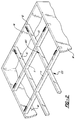
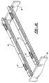
- a letter W indicates vertical supporting walls forming a part of the building structure which I have generally designated BS.
- the wood beams which make up the underlying girder system or assembly, generally designated GS, include wood beams 10 ( Figure 2) connecting the wood beams 11 which extend from one wall W to the other wall W.
- the wood beams 10 and 11 are shown as received in cutouts or recesses 12 provided in the walls W.
- the support walls W can be wood or masonry walls, or poured concrete walls, or made up of any other desired material.
- the beams 10 and 11 may be solid timber beams or adhesively joined laminated or other wood beams.
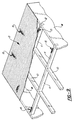
- the reinforced concrete slab is shown as covering a wood deck or decking, generally designated D, which may be made up of side by side, preferably tongue and groove connected boards 13. Other materials may alternately be used, but the wood boards or planks 13 preferentially nail readily to the underlying beams 10 and 11.
- the concrete slab S is a reinforced concrete slab in which there is a wire reinforcement mesh 14 formed of suitable rebar steel rods welded in mesh configuration.
- the concrete slab S which typically is on the order of typically four to six inches in thickness, is subjected to a dead load, which is the weight of the concrete, and a live load, which is variable dependent upon the weights which are borne by the slab S.
- dead and applied loads create compressive stresses in the concrete slab S which need to be relieved by transferring them to the underlying girder system GS, without imposing them on the decking D.
- Figure 13a the bending moment for a single girder 11 of length L between walls W, whether it be of wood or steel construction, is portrayed.
- Figure 13c indicates the reduced amplitude configuration of the bending moment when shearing connectors 15 are used in the matter disclosed in Figures 1 and 2, for example.
- the shearing connectors provided at (i.e. adjacent) the wall supported ends or portions of the beams as shown, the better results achieved with the use of the shearing connectors 15 to be described are evident from a comparison of Figures 13a and 13c by comparing the amplitudes of the bending moments or shear stresses along the girder or beam.
- Diagrams 13, 13b, 13d and 13e are load diagrams which contemplate load application at the connector 15 locations.
- the shearing connectors 15, which are specially formed, rigid metal devices, i.e. welded steel elements, will be available in different sizes or configurations depending on the shear forces which need to be transferred from the reinforced slab to the underlying girders.
- a one bay shearing connector includes a lengthwisely extending, horizontal frame or frame component, member or element, generally designated 17, which as shown comprises transversely spaced apart side plates 18. While the plates 18 are preferred, other possibilities are the use of a channel or annular or polygonal members, either tubular or solid.
- the plate system 18 is preferred because it can be readily provided with transversely aligned reinforcing rod or rebar openings 19 in lengthwisely spaced relation, and, when the concrete slab is cast, the enclosure, generally designated E, formed between the plates 18, will fill with concrete to capture and encapsulate the reinforcement rods or rebars which extend snugly through openings 19 and function to further reinforce the concrete slab S.
- shear load transfer web or end plates 20 which are inset from the ends of the plates 18 as shown to form the end walls of enclosure E, and which have portions or sections 20a projecting below the plates 18.
- the side plates 18 also have downwardly projecting portions or sections 21 which project with the plates 20 and, it will noted, that there are bottoms or bottom walls or plates 22 which span the projecting side plates portions 21 and the projecting web plate sections 20a and fix thereto, as for example, by welding them in position.
- the plates 21, 22, and 20-20a form open ended end compartments, as Figure 3 illustrates.
- the bottoms 22 are provided with fastener openings 23 for receiving fasteners 25 which may typically comprise a wood screw or a bolt.
- pockets 24 are provided in the wood beam or girder 10 or 11, as the case may be, to receive the downwardly projecting portions of the connector provided by members 21, 22 and 20a.
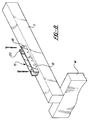
- the plates 18 extend along the upper surface of the beam 11 as shown in Figure 8, for example, and the fasteners 25 are fixed in the beam 11 to resist any tendency of the shearing connector 15 to raise, and to counter the couple formed as illustrated in Figure 7 by the arrows F2 and F3.
- a polyethylene or other plastic parting sheet PS is used between the decking D and the concrete slab S, and this plastic sheet will have cutouts corresponding to the cutouts 16 in deck D.
- the pockets 24 are filled with a cementitious grout compatible with the concrete used in the slab so as to bond thereto.
- the expanding grout employed is compression force resistent when cured, and does not shrink or swell in its cured state so that its installed volume does not change.
- the grout is one which can be purchased and mixed on-site, and, for example, may be the grout designated 1000-1 marketed by Quick-mix Sonder GmbH & Co. in Germany. A generally cementitious product of this type is preferred over other possible resinous alternatives such as epoxy products.
- the wood decking D may be nailed in position in the manner indicated in Figure 1, and the slab S then poured, after the parting sheet PS is also positioned.
- the concrete slab, generally designated S is made up of surrounding portions 27 which embed the side plates 18 in the slab, as well as the portions 28 which fill the connector end compartments above the grout portions 26, and the portions 29, which are received in the central enclosures E of each connector 15 between the side plates 18 and web or end plates 20.
- the reinforcement rods 30, may preferably include generally U-shaped portions, as shown in Figure 1, or may be linear.
- the steel reinforcing rods 30 are sized and configured to the shape of the openings 19 in the plates 18 so as to be snugly received therein and to embed within the concrete portions 29, as well as in the slab portions 27. They maybe formed in the U-shaped configuration shown in Figure 1.
- the ends of the reinforcements bars 30 pass through the openings 19 and are received within the concrete portions 29 of the slab S to be rigidly held in position.
- the compressive forces P1 transfer from the slab S to the transversely disposed load transfer plates or webs 20 which are rigid or what might be termed "bending stiff", so that they are not bent under the stress of the forces P1.
- the dimensions indicated in Figures 4-6 will, for example, provide this rigidity.
- the reinforcement rods 30 also transfer compressive stresses to the left end plate 20 in Figure 7 in view of their snug reception in the openings 19. From the plates 20, the shearing forces P1 due to compression load transfer through the grout 26 in pockets 24 to impose their forces, without slippage, by end grain compression on the girder 10 or 11 as the case may be and subject the girder to tension forces.
- the bending moment out of the eccentric points of load application is taken up by the force couple, F2 and F3, indicated in Figure 7.
- FIG. 2 illustrates the compression resistant concrete slab S connects to the tension resistant girders 10 and 11 only at selected locations adjacent to the wall W supports and the two materials, concrete and wood, are not connected between these shearing connections.
- the two materials act completely separately in this context.
- the pockets 24 will be cut in the beam 10 or 11 a distance of about 2 feet (L-1) from each end of the beam, the next one then being cut a distance of 2L(L-2)+1 inch from each end of the beam.
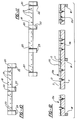
- Figures 10 and 11 illustrate related appropriate distances for the longer connectors with additional downward projections P, as will be noted.
- the wood beam 11 typically will be one foot in height and one half foot in length and a single shearing connector 15 may typically transfer a 200,000 pound compression force to the beam from a slab S which typically may have a depth of 4 inches. Because plates 18 rest on the beam 11 the degree and level of interfacing embedment of the discontinuous connectors 15 in slab S is controlled. The compressive forces are concentrated by the connectors 15 and applied perpendicularly to the grain of the wood beams.
- Figures 10 and 11 designate shearing connectors which are used for two bay and three bay frames, respectively, and it will be noted that the parts remain the same and function in the same way, except that in Figure 10, three web plates 20 and three downwardly projecting projections P are disclosed, whereas in Figure 11 four web plates 20 and four downwardly projecting projections P are disclosed.
- FIG 12 a so-called continuous beam system is illustrated wherein wood girder beam 11 is supported by three walls W.
- shearing connectors 15, 15a, 15c, and 15d are provided adjacent the locations of support as previously.
- the compressive forces applied to shearing connector 15a is applied in an opposite direction to the forces applied to connector 15b and, likewise, the forces applied to connector 15c are applied in a direction opposite to the compressive forces applied to connector 15d.
- the shearing connectors are formed of the same side plates 18 and transverse load applying web plates 20. There are no projections P, however, which extend downwardly and the plates 18 and 20 are simply welded or otherwise suitably secured to the top surface of the upper flanges of the beams 31.
- the side plates 18 are provided with the same openings 19 for capturing the ends of the rods 30 and embedding them in the concrete portions 29.
- the component parts of the building structure BS are all the same and have been accorded the same identifying letters and numerals.
- the plates 20 do not apply the shearing forces by end grain compression, as particularly illustrated in Figure 7, but do transfer shearing forces to the steel beams 31 otherwise in the same general manner.
Applications Claiming Priority (2)
| Application Number | Priority Date | Filing Date | Title |
|---|---|---|---|
| US795674 | 1997-02-06 | ||
| US08/795,674 US5809722A (en) | 1997-02-06 | 1997-02-06 | Girder supported reinforced concrete slab building structures with shearing connectors, and methods of constructing the building structures and connectors |
Publications (3)
| Publication Number | Publication Date |
|---|---|
| EP0857835A2 true EP0857835A2 (de) | 1998-08-12 |
| EP0857835A3 EP0857835A3 (de) | 1999-10-20 |
| EP0857835B1 EP0857835B1 (de) | 2004-05-06 |
Family
ID=25166149
Family Applications (1)
| Application Number | Title | Priority Date | Filing Date |
|---|---|---|---|
| EP98100902A Expired - Lifetime EP0857835B1 (de) | 1997-02-06 | 1998-01-20 | Decke mit Balken und Schubbewehrung |
Country Status (6)
| Country | Link |
|---|---|
| US (1) | US5809722A (de) |
| EP (1) | EP0857835B1 (de) |
| JP (1) | JPH10231578A (de) |
| AT (1) | ATE266130T1 (de) |
| CA (1) | CA2227574C (de) |
| DE (1) | DE69823570T2 (de) |
Cited By (1)
| Publication number | Priority date | Publication date | Assignee | Title |
|---|---|---|---|---|
| IT201700084986A1 (it) * | 2017-07-25 | 2019-01-25 | Laterlite Spa | Connettore perimetrale per il collegamento di un solaio-parete ad una partizione verticale di un edificio |
Families Citing this family (27)
| Publication number | Priority date | Publication date | Assignee | Title |
|---|---|---|---|---|
| AU2531900A (en) * | 1999-06-14 | 2001-01-02 | Zhi Fan | Structure formed of foaming cement and lightweight steel, and a structure system and method of forming the structure system |
| US6755001B2 (en) * | 2000-10-16 | 2004-06-29 | James Hardie Research Pty Limited | Suspended concrete flooring system and method |
| KR100457398B1 (ko) * | 2001-03-15 | 2004-11-16 | 이창남 | 콘볼트를 활용한 철근콘크리트 구조체 보강방법 |
| US6871462B2 (en) * | 2001-07-09 | 2005-03-29 | Board Of Regents Of University Of Nebraska | Composite action system and method |
| AUPS084002A0 (en) * | 2002-03-01 | 2002-03-21 | Blazevic, Paul | Building panel and construction method |
| ECSP034697A (es) * | 2003-07-18 | 2004-06-28 | Cabezas Pedro Nel Fernando Ospina | Sistema constructivo estructural mixto integral |
| DE10351989A1 (de) * | 2003-10-23 | 2005-06-09 | Bathon, Leander | Holz-Beton-Verbundsysteme aus Holzbauteilen, Zwischenschichten und Betonbauteilen |
| US7140158B2 (en) * | 2004-07-06 | 2006-11-28 | William Steadman | Composite beam |
| WO2006018908A1 (ja) * | 2004-08-18 | 2006-02-23 | Taisei Corporation | せん断力補強構造及びせん断力補強部材 |
| KR100641607B1 (ko) * | 2005-06-02 | 2006-11-02 | 한국건설기술연구원 | 전단연결재 일체형 섬유강화플라스틱 바닥판 모듈 및 이를이용한 콘크리트 합성 바닥판 |
| DE202006000593U1 (de) * | 2006-01-13 | 2006-05-18 | Bathon, Leander, Prof. Dr. | Bauwerke in Holz-Beton-Verbundbauweise |
| US7934347B2 (en) * | 2006-07-28 | 2011-05-03 | Paul Brienen | Coupling beam and method of use in building construction |
| US20080295430A1 (en) * | 2007-05-29 | 2008-12-04 | Lewis Michael C | Thin shell cementitious coated shear wall structural panel assembly and method of manufacture |
| US7739844B2 (en) * | 2008-05-27 | 2010-06-22 | American Fortress Homes, Inc. | Composite building panel |
| US20120073230A1 (en) * | 2010-09-24 | 2012-03-29 | Fmi Products, Llc | Pre-engineered brick panel and methods of making and installing same |
| CN102888930A (zh) * | 2011-07-18 | 2013-01-23 | 湖南邱则有专利战略策划有限公司 | 装配式空腹网格板楼盖 |
| JP5903237B2 (ja) * | 2011-10-11 | 2016-04-13 | 株式会社竹中工務店 | 合成床構造及び耐火構造物並びに合成床構造の構築方法 |
| US8943776B2 (en) * | 2012-09-28 | 2015-02-03 | Ispan Systems Lp | Composite steel joist |
| ES2511992B1 (es) * | 2013-04-08 | 2015-07-28 | Carlos González Bravo | Conector para conexión de estructuras mixtas de madera-hormigón |
| WO2016049758A1 (en) * | 2014-09-30 | 2016-04-07 | UNIVERSITé LAVAL | Built-up system, connector thereof, and method of making same |
| CZ2014901A3 (cs) | 2014-12-12 | 2016-06-22 | Vysoká Škola Báňská - Technická Univerzita Ostrava | Spřahovací dílec pro dřevobetonovou stropní spřaženou konstrukci |
| CN104895231B (zh) * | 2015-04-30 | 2017-04-12 | 宁波大学 | 一种装配式组合楼板及其制造方法 |
| US20180347191A1 (en) * | 2017-06-01 | 2018-12-06 | 9360-4742 Quebec Inc. | Prefabricated concrete slab floor and method of fabricating the same |
| CN108412049A (zh) * | 2018-03-05 | 2018-08-17 | 苏州科技大学 | 一种木-混凝土组合梁抗剪连接件推出试验试件 |
| US11072925B2 (en) * | 2018-12-12 | 2021-07-27 | Dalian University Of Technology | Rapid construction method for flush assembly of the prefabricated steel beam and the floor slab |
| CA3050000A1 (en) * | 2019-07-16 | 2021-01-16 | Invent To Build Inc. | Concrete fillable steel joist |
| FI129949B (fi) * | 2019-10-16 | 2022-11-30 | Finnfoam Oy | Lämmöneristelevy ja sen käyttö |
Citations (5)
| Publication number | Priority date | Publication date | Assignee | Title |
|---|---|---|---|---|
| DE942891C (de) * | 1950-05-13 | 1956-05-09 | Ernst Kuss | Gespannte Decken und zu ihrer Herstellung dienender Ursprungstraeger |
| DE1609322A1 (de) * | 1961-02-22 | 1970-09-03 | Gutehoffnungshuette Sterkrade | Leichtbau-Verbunddecke |
| EP0345620A2 (de) * | 1988-06-07 | 1989-12-13 | Hans-Peter Dr.-Ing. Andrä | Träger aus Stahlbeton mit Plattenbalken-Querschnitt |
| EP0613985A1 (de) * | 1993-03-03 | 1994-09-07 | Daniel Gauthier | Gemischter Holz-Beton Baukörper |
| EP0717149A1 (de) * | 1994-12-13 | 1996-06-19 | SOPRESE (société à responsabilité limitée) | Holz-Beton Verbundkonstruktion, insbesondere für die Herstellung von Brückendecken |
Family Cites Families (17)
| Publication number | Priority date | Publication date | Assignee | Title |
|---|---|---|---|---|
| GB591804A (en) * | 1941-01-24 | 1947-08-29 | Erwin Maier | Improvements in and relating to beams and like structural members |
| FR726897A (fr) * | 1931-11-25 | 1932-06-04 | Brev De Construction S A Et | Poutrelle et son application à la constitution des planchers |
| US2163889A (en) * | 1938-01-15 | 1939-06-27 | Ernest A Podd | Channel chair |
| US2358147A (en) * | 1942-11-06 | 1944-09-12 | Richard R Colburn | Concrete structure |
| AT164109B (de) * | 1945-12-11 | 1949-10-10 | Karl Anton Bergmann | Eisenbetondecke |
| US2760450A (en) * | 1953-08-04 | 1956-08-28 | Easybow Engineering & Res Co | Bowstring truss and method of making the same |
| DE1005710B (de) * | 1953-09-05 | 1957-04-04 | Richard Doorentz | Stahlbetondecke auf frei gelagerten Metalltraegern |
| US3528209A (en) * | 1967-10-20 | 1970-09-15 | Jack Schillinger | Prestressed concrete beams with wooden inserts and method of forming the same |
| US3736716A (en) * | 1970-04-11 | 1973-06-05 | Long Span Bridge Consultants I | Means for reducing slippage of steel beam relative to concrete slab |
| BE795916A (fr) * | 1973-02-26 | 1973-06-18 | Noel Albert D G | Elements de construction mixtes 'acier-beton' |
| GB2053308B (en) * | 1979-07-06 | 1983-04-07 | Conder International Ltd | Beam floor or roof construction |
| DE3366105D1 (en) * | 1982-09-20 | 1986-10-16 | South African Inventions | Composite floor structures |
| US4597233A (en) * | 1984-03-05 | 1986-07-01 | Rongoe Jr James | Girder system |
| DE3610030C1 (de) * | 1986-03-25 | 1987-02-05 | Rapp Albert Bruno | Bauelement fuer Hochbauwerke |
| US5634308A (en) * | 1992-11-05 | 1997-06-03 | Doolan; Terence F. | Module combined girder and deck construction |
| CH687397A5 (fr) * | 1992-11-14 | 1996-11-29 | Bettex Fabienne | Plancher mixte bois-beton. |
| US5509243A (en) * | 1994-01-21 | 1996-04-23 | Bettigole; Neal H. | Exodermic deck system |
-
1997
- 1997-02-06 US US08/795,674 patent/US5809722A/en not_active Expired - Fee Related
-
1998
- 1998-01-20 DE DE69823570T patent/DE69823570T2/de not_active Expired - Fee Related
- 1998-01-20 EP EP98100902A patent/EP0857835B1/de not_active Expired - Lifetime
- 1998-01-20 AT AT98100902T patent/ATE266130T1/de not_active IP Right Cessation
- 1998-01-20 CA CA002227574A patent/CA2227574C/en not_active Expired - Fee Related
- 1998-02-05 JP JP10024771A patent/JPH10231578A/ja active Pending
Patent Citations (5)
| Publication number | Priority date | Publication date | Assignee | Title |
|---|---|---|---|---|
| DE942891C (de) * | 1950-05-13 | 1956-05-09 | Ernst Kuss | Gespannte Decken und zu ihrer Herstellung dienender Ursprungstraeger |
| DE1609322A1 (de) * | 1961-02-22 | 1970-09-03 | Gutehoffnungshuette Sterkrade | Leichtbau-Verbunddecke |
| EP0345620A2 (de) * | 1988-06-07 | 1989-12-13 | Hans-Peter Dr.-Ing. Andrä | Träger aus Stahlbeton mit Plattenbalken-Querschnitt |
| EP0613985A1 (de) * | 1993-03-03 | 1994-09-07 | Daniel Gauthier | Gemischter Holz-Beton Baukörper |
| EP0717149A1 (de) * | 1994-12-13 | 1996-06-19 | SOPRESE (société à responsabilité limitée) | Holz-Beton Verbundkonstruktion, insbesondere für die Herstellung von Brückendecken |
Cited By (1)
| Publication number | Priority date | Publication date | Assignee | Title |
|---|---|---|---|---|
| IT201700084986A1 (it) * | 2017-07-25 | 2019-01-25 | Laterlite Spa | Connettore perimetrale per il collegamento di un solaio-parete ad una partizione verticale di un edificio |
Also Published As
| Publication number | Publication date |
|---|---|
| CA2227574C (en) | 2004-05-18 |
| ATE266130T1 (de) | 2004-05-15 |
| EP0857835B1 (de) | 2004-05-06 |
| DE69823570D1 (de) | 2004-06-09 |
| DE69823570T2 (de) | 2005-04-07 |
| JPH10231578A (ja) | 1998-09-02 |
| EP0857835A3 (de) | 1999-10-20 |
| CA2227574A1 (en) | 1998-08-06 |
| US5809722A (en) | 1998-09-22 |
Similar Documents
| Publication | Publication Date | Title |
|---|---|---|
| CA2227574C (en) | Girder supported reinforced concrete slab building structures with shearing connectors, and methods of constructing the building structures and connectors | |
| US11598056B2 (en) | Module for a structure | |
| US6293063B2 (en) | Cast-in-place hybrid building system | |
| US4604841A (en) | Continuous, precast, prestressed concrete bridge deck panel forms, precast parapets, and method of construction | |
| NZ296818A (en) | Modular precast wall with mortar joints, spacer provides joint space for mortar | |
| CA2440765C (en) | Composite structural framing system | |
| US4809474A (en) | Prestressed composite floor slab and method of making the same | |
| US5809713A (en) | Structural elements | |
| US7937901B2 (en) | Tendon-identifying, post tensioned concrete flat plate slab and method and apparatus for constructing same | |
| WO1997014849A1 (en) | Bridge deck system | |
| JP2928475B2 (ja) | 合成床版橋用プレキャストコンクリート桁 | |
| US20030061672A1 (en) | Bridge construction method and composite girder for use in same | |
| SU1261998A1 (ru) | Балка | |
| US3127704A (en) | Floor and ceiling construction | |
| JP3245106B2 (ja) | プレキャストプレストレスコンクリート床版を使用した鋼合成複合橋 | |
| GB2614906A (en) | Composite floor construction | |
| JPH041137B2 (de) | ||
| Stalnaker et al. | Formwork for concrete | |
| OA18683A (en) | A Module for a structure | |
| CA2357387A1 (en) | Bridge construction method and composite girder for use in same | |
| CA2234766A1 (en) | Bridge deck system | |
| WO2015144673A1 (en) | A slab-shaped concrete material building element, a building structure including the concrete building element, and a method of building the building structure |
Legal Events
| Date | Code | Title | Description |
|---|---|---|---|
| PUAI | Public reference made under article 153(3) epc to a published international application that has entered the european phase |
Free format text: ORIGINAL CODE: 0009012 |
|
| AK | Designated contracting states |
Kind code of ref document: A2 Designated state(s): AT DE ES FR GB IT PT |
|
| AX | Request for extension of the european patent |
Free format text: AL;LT;LV;MK;RO;SI |
|
| PUAL | Search report despatched |
Free format text: ORIGINAL CODE: 0009013 |
|
| AK | Designated contracting states |
Kind code of ref document: A3 Designated state(s): AT BE CH DE DK ES FI FR GB GR IE IT LI LU MC NL PT SE |
|
| AX | Request for extension of the european patent |
Free format text: AL;LT;LV;MK;RO;SI |
|
| RIC1 | Information provided on ipc code assigned before grant |
Free format text: 6E 04B 5/43 A, 6E 04B 5/23 B, 6E 04B 5/29 B |
|
| 17P | Request for examination filed |
Effective date: 20000420 |
|
| AKX | Designation fees paid |
Free format text: AT BE CH DE DK ES FI LI |
|
| RBV | Designated contracting states (corrected) |
Designated state(s): AT DE ES FR GB IT PT |
|
| 17Q | First examination report despatched |
Effective date: 20021112 |
|
| GRAP | Despatch of communication of intention to grant a patent |
Free format text: ORIGINAL CODE: EPIDOSNIGR1 |
|
| RTI1 | Title (correction) |
Free format text: GIRDER SUPPORTED REINFORCED CONCRETE SLAB BUILDING STRUCTURES WITH SHEARING CONNECTORS |
|
| GRAS | Grant fee paid |
Free format text: ORIGINAL CODE: EPIDOSNIGR3 |
|
| GRAA | (expected) grant |
Free format text: ORIGINAL CODE: 0009210 |
|
| AK | Designated contracting states |
Kind code of ref document: B1 Designated state(s): AT DE ES FR GB IT PT |
|
| PG25 | Lapsed in a contracting state [announced via postgrant information from national office to epo] |
Ref country code: IT Free format text: LAPSE BECAUSE OF FAILURE TO SUBMIT A TRANSLATION OF THE DESCRIPTION OR TO PAY THE FEE WITHIN THE PRESCRIBED TIME-LIMIT;WARNING: LAPSES OF ITALIAN PATENTS WITH EFFECTIVE DATE BEFORE 2007 MAY HAVE OCCURRED AT ANY TIME BEFORE 2007. THE CORRECT EFFECTIVE DATE MAY BE DIFFERENT FROM THE ONE RECORDED. Effective date: 20040506 Ref country code: AT Free format text: LAPSE BECAUSE OF FAILURE TO SUBMIT A TRANSLATION OF THE DESCRIPTION OR TO PAY THE FEE WITHIN THE PRESCRIBED TIME-LIMIT Effective date: 20040506 |
|
| REG | Reference to a national code |
Ref country code: GB Ref legal event code: FG4D |
|
| REF | Corresponds to: |
Ref document number: 69823570 Country of ref document: DE Date of ref document: 20040609 Kind code of ref document: P |
|
| PG25 | Lapsed in a contracting state [announced via postgrant information from national office to epo] |
Ref country code: ES Free format text: LAPSE BECAUSE OF FAILURE TO SUBMIT A TRANSLATION OF THE DESCRIPTION OR TO PAY THE FEE WITHIN THE PRESCRIBED TIME-LIMIT Effective date: 20040817 |
|
| ET | Fr: translation filed | ||
| PLBE | No opposition filed within time limit |
Free format text: ORIGINAL CODE: 0009261 |
|
| STAA | Information on the status of an ep patent application or granted ep patent |
Free format text: STATUS: NO OPPOSITION FILED WITHIN TIME LIMIT |
|
| 26N | No opposition filed |
Effective date: 20050208 |
|
| PG25 | Lapsed in a contracting state [announced via postgrant information from national office to epo] |
Ref country code: PT Free format text: LAPSE BECAUSE OF NON-PAYMENT OF DUE FEES Effective date: 20041006 |
|
| PGFP | Annual fee paid to national office [announced via postgrant information from national office to epo] |
Ref country code: GB Payment date: 20090122 Year of fee payment: 12 |
|
| PGFP | Annual fee paid to national office [announced via postgrant information from national office to epo] |
Ref country code: DE Payment date: 20090331 Year of fee payment: 12 |
|
| PGFP | Annual fee paid to national office [announced via postgrant information from national office to epo] |
Ref country code: FR Payment date: 20090115 Year of fee payment: 12 |
|
| GBPC | Gb: european patent ceased through non-payment of renewal fee |
Effective date: 20100120 |
|
| REG | Reference to a national code |
Ref country code: FR Ref legal event code: ST Effective date: 20100930 |
|
| PG25 | Lapsed in a contracting state [announced via postgrant information from national office to epo] |
Ref country code: FR Free format text: LAPSE BECAUSE OF NON-PAYMENT OF DUE FEES Effective date: 20100201 |
|
| PG25 | Lapsed in a contracting state [announced via postgrant information from national office to epo] |
Ref country code: DE Free format text: LAPSE BECAUSE OF NON-PAYMENT OF DUE FEES Effective date: 20100803 |
|
| PG25 | Lapsed in a contracting state [announced via postgrant information from national office to epo] |
Ref country code: GB Free format text: LAPSE BECAUSE OF NON-PAYMENT OF DUE FEES Effective date: 20100120 |