EP0857099B1 - Outil a brosser adaptable sur une meuleuse d'angle - Google Patents
Outil a brosser adaptable sur une meuleuse d'angle Download PDFInfo
- Publication number
- EP0857099B1 EP0857099B1 EP96936521A EP96936521A EP0857099B1 EP 0857099 B1 EP0857099 B1 EP 0857099B1 EP 96936521 A EP96936521 A EP 96936521A EP 96936521 A EP96936521 A EP 96936521A EP 0857099 B1 EP0857099 B1 EP 0857099B1
- Authority
- EP
- European Patent Office
- Prior art keywords
- tool
- disk
- grinder
- bristles
- working zone
- Prior art date
- Legal status (The legal status is an assumption and is not a legal conclusion. Google has not performed a legal analysis and makes no representation as to the accuracy of the status listed.)
- Expired - Lifetime
Links
- 238000009987 spinning Methods 0.000 claims abstract description 9
- 238000005520 cutting process Methods 0.000 claims abstract description 8
- 230000009471 action Effects 0.000 claims description 7
- 230000002093 peripheral effect Effects 0.000 claims 1
- 239000000463 material Substances 0.000 description 23
- 238000000034 method Methods 0.000 description 9
- 239000002184 metal Substances 0.000 description 8
- 229910052751 metal Inorganic materials 0.000 description 8
- 239000004033 plastic Substances 0.000 description 5
- 229920003023 plastic Polymers 0.000 description 5
- 229910001209 Low-carbon steel Inorganic materials 0.000 description 4
- 239000012858 resilient material Substances 0.000 description 4
- 238000007493 shaping process Methods 0.000 description 4
- 229910000831 Steel Inorganic materials 0.000 description 3
- 239000000835 fiber Substances 0.000 description 3
- 230000004048 modification Effects 0.000 description 3
- 238000012986 modification Methods 0.000 description 3
- 125000006850 spacer group Chemical group 0.000 description 3
- 230000003068 static effect Effects 0.000 description 3
- 239000010959 steel Substances 0.000 description 3
- 239000002023 wood Substances 0.000 description 3
- XEEYBQQBJWHFJM-UHFFFAOYSA-N Iron Chemical compound [Fe] XEEYBQQBJWHFJM-UHFFFAOYSA-N 0.000 description 2
- 239000003082 abrasive agent Substances 0.000 description 2
- 238000013459 approach Methods 0.000 description 2
- 230000008901 benefit Effects 0.000 description 2
- 239000000919 ceramic Substances 0.000 description 2
- 238000010276 construction Methods 0.000 description 2
- 230000000994 depressogenic effect Effects 0.000 description 2
- 239000000428 dust Substances 0.000 description 2
- 230000006872 improvement Effects 0.000 description 2
- 238000003756 stirring Methods 0.000 description 2
- 235000001674 Agaricus brunnescens Nutrition 0.000 description 1
- 229910001369 Brass Inorganic materials 0.000 description 1
- 229910000906 Bronze Inorganic materials 0.000 description 1
- 208000015943 Coeliac disease Diseases 0.000 description 1
- RYGMFSIKBFXOCR-UHFFFAOYSA-N Copper Chemical compound [Cu] RYGMFSIKBFXOCR-UHFFFAOYSA-N 0.000 description 1
- 229910000599 Cr alloy Inorganic materials 0.000 description 1
- 241000640843 Epipactis gigantea Species 0.000 description 1
- 229910000640 Fe alloy Inorganic materials 0.000 description 1
- 229910000760 Hardened steel Inorganic materials 0.000 description 1
- 239000004809 Teflon Substances 0.000 description 1
- 229920006362 Teflon® Polymers 0.000 description 1
- 238000005299 abrasion Methods 0.000 description 1
- 238000004026 adhesive bonding Methods 0.000 description 1
- 229910045601 alloy Inorganic materials 0.000 description 1
- 239000000956 alloy Substances 0.000 description 1
- 230000004075 alteration Effects 0.000 description 1
- PNEYBMLMFCGWSK-UHFFFAOYSA-N aluminium oxide Inorganic materials [O-2].[O-2].[O-2].[Al+3].[Al+3] PNEYBMLMFCGWSK-UHFFFAOYSA-N 0.000 description 1
- 230000009286 beneficial effect Effects 0.000 description 1
- 239000010951 brass Substances 0.000 description 1
- 239000010974 bronze Substances 0.000 description 1
- 230000000711 cancerogenic effect Effects 0.000 description 1
- 231100000315 carcinogenic Toxicity 0.000 description 1
- 238000005266 casting Methods 0.000 description 1
- 239000000788 chromium alloy Substances 0.000 description 1
- 238000001816 cooling Methods 0.000 description 1
- 229910052802 copper Inorganic materials 0.000 description 1
- 239000010949 copper Substances 0.000 description 1
- KUNSUQLRTQLHQQ-UHFFFAOYSA-N copper tin Chemical compound [Cu].[Sn] KUNSUQLRTQLHQQ-UHFFFAOYSA-N 0.000 description 1
- 230000007547 defect Effects 0.000 description 1
- 238000004512 die casting Methods 0.000 description 1
- 230000000694 effects Effects 0.000 description 1
- 230000002708 enhancing effect Effects 0.000 description 1
- 208000016253 exhaustion Diseases 0.000 description 1
- 239000002360 explosive Substances 0.000 description 1
- 239000011152 fibreglass Substances 0.000 description 1
- 239000000945 filler Substances 0.000 description 1
- 239000003365 glass fiber Substances 0.000 description 1
- 230000036541 health Effects 0.000 description 1
- 238000001746 injection moulding Methods 0.000 description 1
- 229910052742 iron Inorganic materials 0.000 description 1
- 238000003698 laser cutting Methods 0.000 description 1
- 210000004072 lung Anatomy 0.000 description 1
- 239000011159 matrix material Substances 0.000 description 1
- 230000007246 mechanism Effects 0.000 description 1
- 238000002844 melting Methods 0.000 description 1
- 230000008018 melting Effects 0.000 description 1
- 150000002739 metals Chemical class 0.000 description 1
- 229920001343 polytetrafluoroethylene Polymers 0.000 description 1
- 239000004810 polytetrafluoroethylene Substances 0.000 description 1
- 238000003825 pressing Methods 0.000 description 1
- 230000008569 process Effects 0.000 description 1
- 230000008439 repair process Effects 0.000 description 1
- 239000007787 solid Substances 0.000 description 1
- 239000010935 stainless steel Substances 0.000 description 1
- 229910001220 stainless steel Inorganic materials 0.000 description 1
- 231100000331 toxic Toxicity 0.000 description 1
- 230000002588 toxic effect Effects 0.000 description 1
- WFKWXMTUELFFGS-UHFFFAOYSA-N tungsten Chemical compound [W] WFKWXMTUELFFGS-UHFFFAOYSA-N 0.000 description 1
- 229910052721 tungsten Inorganic materials 0.000 description 1
- 239000010937 tungsten Substances 0.000 description 1
- 239000002699 waste material Substances 0.000 description 1
Images

Classifications
-
- B—PERFORMING OPERATIONS; TRANSPORTING
- B24—GRINDING; POLISHING
- B24D—TOOLS FOR GRINDING, BUFFING OR SHARPENING
- B24D13/00—Wheels having flexibly-acting working parts, e.g. buffing wheels; Mountings therefor
- B24D13/02—Wheels having flexibly-acting working parts, e.g. buffing wheels; Mountings therefor acting by their periphery
- B24D13/06—Wheels having flexibly-acting working parts, e.g. buffing wheels; Mountings therefor acting by their periphery the flaps or strips being individually attached
-
- A—HUMAN NECESSITIES
- A46—BRUSHWARE
- A46B—BRUSHES
- A46B9/00—Arrangements of the bristles in the brush body
- A46B9/06—Arrangement of mixed bristles or tufts of bristles, e.g. wire, fibre, rubber
-
- B—PERFORMING OPERATIONS; TRANSPORTING
- B24—GRINDING; POLISHING
- B24B—MACHINES, DEVICES, OR PROCESSES FOR GRINDING OR POLISHING; DRESSING OR CONDITIONING OF ABRADING SURFACES; FEEDING OF GRINDING, POLISHING, OR LAPPING AGENTS
- B24B23/00—Portable grinding machines, e.g. hand-guided; Accessories therefor
- B24B23/02—Portable grinding machines, e.g. hand-guided; Accessories therefor with rotating grinding tools; Accessories therefor
- B24B23/028—Angle tools
-
- B—PERFORMING OPERATIONS; TRANSPORTING
- B24—GRINDING; POLISHING
- B24D—TOOLS FOR GRINDING, BUFFING OR SHARPENING
- B24D13/00—Wheels having flexibly-acting working parts, e.g. buffing wheels; Mountings therefor
- B24D13/02—Wheels having flexibly-acting working parts, e.g. buffing wheels; Mountings therefor acting by their periphery
- B24D13/10—Wheels having flexibly-acting working parts, e.g. buffing wheels; Mountings therefor acting by their periphery comprising assemblies of brushes
-
- B—PERFORMING OPERATIONS; TRANSPORTING
- B24—GRINDING; POLISHING
- B24D—TOOLS FOR GRINDING, BUFFING OR SHARPENING
- B24D13/00—Wheels having flexibly-acting working parts, e.g. buffing wheels; Mountings therefor
- B24D13/14—Wheels having flexibly-acting working parts, e.g. buffing wheels; Mountings therefor acting by the front face
- B24D13/147—Wheels having flexibly-acting working parts, e.g. buffing wheels; Mountings therefor acting by the front face comprising assemblies of felted or spongy material; comprising pads surrounded by a flexible material
-
- B—PERFORMING OPERATIONS; TRANSPORTING
- B24—GRINDING; POLISHING
- B24D—TOOLS FOR GRINDING, BUFFING OR SHARPENING
- B24D13/00—Wheels having flexibly-acting working parts, e.g. buffing wheels; Mountings therefor
- B24D13/20—Mountings for the wheels
-
- B—PERFORMING OPERATIONS; TRANSPORTING
- B24—GRINDING; POLISHING
- B24D—TOOLS FOR GRINDING, BUFFING OR SHARPENING
- B24D7/00—Bonded abrasive wheels, or wheels with inserted abrasive blocks, designed for acting otherwise than only by their periphery, e.g. by the front face; Bushings or mountings therefor
- B24D7/18—Wheels of special form
-
- A—HUMAN NECESSITIES
- A46—BRUSHWARE
- A46B—BRUSHES
- A46B2200/00—Brushes characterized by their functions, uses or applications
- A46B2200/30—Brushes for cleaning or polishing
- A46B2200/3093—Brush with abrasive properties, e.g. wire bristles
Definitions
- This invention relates to the field of disc-shaped rotating abrading tools of the type having manufactured surfaces for abrading and forming materials, and in particular this invention relates to a wire brush accessory which is adapted for use with a hand-held angle grinder.
- a number of applications in the construction or repair of solid articles involve the selective removal of material from a bulk in order to produce a desired conformation or shape.
- a builder may remove some wood from a beam in order to produce a neat fit - more likely if the house being built is non-rectangular;
- a foundry removes surplus metal from sprues or joints between mould parts when producing a casting;
- a wood carver selectively removes wood in order to produce a carving;
- a panel beater frequently removes surplus plastic filler which was placed within a defect in an automotive panel to build it up, so that the outline conforms with the original outline of the panel; or a boat builder may have to remove kilograms of material, such as lead-filled fibreglass when shaping or repairing a hull.
- One form of tool used for removal of loosely adhered material is a cup-shaped wire brush rotating on a spindle.
- One such device is described in DE-A-25 02 698, which forms the base for the preamble of claim 1.
- a first aspect comprised an accessory for a grinder including a rotatable tool having a shape substantially that of a disk, having an axis of rotation and capable of being mounted on an arbor of an angle grinder, characterised in that the rotatable tool is provided with at least one working zone within an active zone extending inwardly from the perimeter of the tool; and rest means extending substantially inwardly from the working zone of the tool, which rest means is displaced from the working zone along the line of the axis of rotation.
- the working zone is co-extensive with the active zone.
- the previous Application comprises an accessory for a grinder characterised in that the rest means is concentric with and supported on the rotatable tool.
- the previous Application comprises an accessory for a grinder characterised in that the rest means comprises a portion of a convex working surface of the rotatable tool and the rest means includes at least one rubbing surface located between the active zone and the axis of rotation.
- the previous Application comprises an accessory for a grinder characterised in that the rest means comprises a fixed rubbing surface or nose supported on the angle grinder and displaced so as to be supported beyond the rotatable tool. (By “beyond” we mean beyond the end of the arbor, or below the tool as it is normally held).
- the previous Application comprises an accessory for a grinder comprising a rotable tool characterised in that the working zone comprises at least one area within the active zone of the rotatable tool, and the active zone surface extends radially inward over the working surface from the perimeter for up to two thirds and preferably one third of the radius of the rotatable tool.
- the invention provides a further extension of the general concepts embodied in the previous Application described above.
- the invention provides an accessory for a grinder comprising a rotatable disk-shaped tool, having an axis of rotation and adapted to be mounted on an arbor of an angle grinder, the accessory being provided with a working zone located on the rotatable disk-shaped tool and extending inwardly from the perimeter of the tool; and rest means extending substantially inwardly from the working zone of the tool, which rest means is located radially inward from the working zone and displaced by a fixed distance along the line of the axis of rotation of the tool and away from the grinder, wherein the working zone of the rotatable tool is provided with a plurality of stiff bristles capable of performing a cutting or abrading action when in rotational motion, the bristles projecting from the surface of the working zone and the length of the bristles being such that a portion of the rest means can be contacted with a work surface without contact occurring between the bristles and the work surface
- At least one viewing aperture is provided through the disk of the rotatable tool and at least one viewing aperture may, when the tool is rotating, also serve to cause air movement.
- the grinder has a central recessed mounting aperture provided with gripping means or clutch means capable of disengagement substantially as long as a torque applied between the rotatable spindle and the tool exceeds a predetermined amount and optionally a resilient mounting means capable of reducing vibration.
- the preferred disk-shaped rotatable abrading tool is mounted on a rotatable spindle, and comprises an active zone on said rotatable abrading tool, which active zone comprises a least one working zone comprising stiff bristles capable of removing material from the work surface, and rest means (a rest zone) dispaced along the axis of rotation by a fixed amount from the working zone, which rest means, in use, permits control of the shaping action of the grinder system by first contacting the rest means with the work surface and then tilting the grinder system to cause or increase engagement of the bristles in the working zone with the work surface.
- the rest means comprises a rubbing surface provided with rotational bearing means, which preferably moves on the same axis as the disk-shaped tool, so that in use the rubbing surface may rotate independently of the rotatable tool.
- At least one viewing aperture is provided through the tool and in which at least one viewing aperture may when the tool is rotating also serve as to cause air movement.
- the rotatable abrading tool of the invention preferably has a central mounting aperture adapted for attachment to a rotatable spindle.
- the rotatable tool has a central recessed mounting aperture adapted for attachment to a rotatable spindle and is provided with clutch means capable of disengagement while a torque applied between the rotatable spindle and the tool exceeds a predetermined amount.
- the central recessed mounting aperture is also provided with resilient mounting means capable of reducing vibration caused by eccentricity.
- the means for attachment of the tool comprises a shaped depression, shaped to match the profile of an arbor and nut.
- the nut includes means to impose a grip on the tool using static friction, and preferably the static friction is overcome at a torque less than that which can damage a means for driving the rotary shaft.
- the tool is adapted for use with an ordinary angle grinder.
- it may be adapted for use with other rotatable powered machines.
- the angle grinder may be fitted with a guard, in order to control swarf.
- the tool of the invention provides a method for shaping material, comprising the steps of (a) causing a tool according to the above description having viewing apertures therein to be affixed to an angle grinder or the like, (b) applying power to the angle grinder motor, (c) holding the tool against the work while tilted at a low angle to it (so that the rest means contacts the surface but the working surface is not engaged) and raising the tilt to a higher angle so that the working surface contacts the work surface with a controlled pressure, and (d) drawing the tool towards the user meanwhile having the opportunity to view the work through apertures in the rotating tool.
- the tool is adapted for mounting upon the spindle or arbor of an angle grinder tool and for this purpose the tool is provided with an optionally threaded central mounting aperture.
- the border of the central aperture is depressed towards the inner surface of the tool.
- the tool is made of mild steel although alternatively it may be made from a hardenable metal or alloy or from a plastics material.
- the tool may be made by other processes, including pressure die-casting.
- a mild steel disk 2 to 6 mm thick provides the basi of the tool.
- the disk may be flat and in this case there may be two active zones, one on each major surface,, although only one can be used at one time.
- the disk is deformed into a conical or curved profile with at least the active zone of the outer surface being a convex surface.
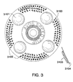
- Fig 2 shows a variety of wire brush disks, in section, suitable for an angle grinder. These are shown as complete disks because the prototype (see Fig 3) was made in this way.
- the lower version is preferred over the upper version (for most purposes) because the longer bristles have a longer distance in which to flex and should last longer before breaking.
- the disk has a central "bare" zone which may be used as a rest zone in accordance with the principles of the invention. (3002 and 3004 represent means for attachment to the arbor of an angle grinder).
- Fig 3 shows a face view 3100 of a prototype wire brush disk for an angle grinder.
- the outer perimeter of the tool is provided with a plurality of stiff bristles or wires capable of performing a cutting or abrading action when spinning at typical angle grinder speeds.
- these were made by manually fitting bristles though holes drilled in a blade, and gluing them into place after adjusting for length.
- a number of viewing holes 3101 have been made (also useful for enhancing air movement and possibly their edges are also useable for cutting) and a number of bristles of a suitable iron or steel wire have been embedded in the disk towards its periphery, as shown at 2302.
- a side view of one of the bristled sectors is shown at 3104, with protruding bristles 3103..
- the materials from which the bristles are made are preferably steel or other alloys of iron but other extrudable metals such as copper, brass, bronze, tungsten and the like can be used depending on the toughness requirements imposed by the intended applications In some situations ceramic fibers may be substituted for the metal fibers providing the bristles. Suitable ceramic bristles include alumina fibers.
- the invention is used primarily as a component of a hand-held grinder system. As practically all of these are for the type of machine known as an angle grinder we shall predominantly refer to angle grinders. In addition the invention will be more particularly described with reference to the above Drawings.
- the angle grinder is provided with a rest point, (or rest means), comprising means to lean or rest the tool on the work surface, while in use, and from that rest point, gradually slope or incline the machine until the bristles in the working zone of the tool start abrading the work surface. From this time the grinder may be slid or "stroked" preferably towards the operator.
- the apertures or viewing holes in the tool permit the surface being treated to be inspected prior to abrading.
- the rest means can optionally be provided on the body of the angle grinder; most conveniently as part of a guard beneath a portion of the wheel (Figs 4 and 5) or alternatively we can provide that the rest means is located on the spinning disk, where it may form:-
- Intimately associated with this method-based concept is the provision of abrading tools having an active, or working, zone comprising the entire outer perimeter extending inwards by about one third of the radius, or an active zone comprising isolated abrading sites within the entire active zone, and a rest zone located radially inward of the working zone.
- the preferred tool comprises an optionally perforated metal disk capable of attachment to the angle grinder shaft.
- Preferred disks are convex, like the saucer for a cup, and have an active working zone with abrading bristles located on or about the convex perimeter.
- the tool is adapted to be used with a conventional angle grinder of the widely used type having a typical no-load rotation speed of 11,000 rpm, driven usually by a universal (AC/DC) brush motor.
- Conventional angle grinders provide a drive shaft onto which various discs (normally of abrasive material) may be mounted and spun at a high speed.
- a typical angle grinder is the single-speed 115 mm grinder sold as the "AEG WSL115" (TM) (600 watts). This size of motor provides an acceptable power for the prototype disks.
- a variable-speed angle grinder may be an advantage.
- the work-material and the working surface of the disk are brought together so that the work-material approaches the working zone from the centre of the disk and the trailing edge of the working zone is the disk edge.
- the work at or close to the site of the abrading is partially visible through holes cut through the disk.
- the preferred movement is to drag the tool towards the user, or stroke it over the work material, while the working zone engages the material.
- the preferred apertures allow the user to see, through the disk, the site where the tool is about to cut or abrade. There is relatively little or no "kick" from the tool (not often the case with ordinary angle grinder tools or saw-like modifications,), and it is easy to hold and control the machine during operation in order to carry out relatively fine movements.
- the angle made by the handle of the angle grinder to the work is typically about 30 degrees, (varied by the user from about 15 degrees to about 40 degrees) using the example cutter, but this depends on the shape to be formed.
- the angle allows the effective tooth protrusion amount to be varied.
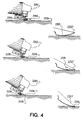
- Fig 4 illustrates this method, (minus the bristles for the sake of clarity), in which the rest means is a nose (left side series) or a rubbing surface.
- the rest means is a nose (left side series) or a rubbing surface.
- the rest means is a nose (left side series) or a rubbing surface.
- At the left are three variations (2201, 2202. and 2203) of tilt (respective to a work surface 2200) of an angle grinder with a nose 2205 and a flat disk 2204; wherein the grinder system is being tilted on its nose 2205 so that the rotating disk 2204 approaches the work. In the centre left drawing the disk is just contacting the work.
- Disks can be curved in profile, or include a conic section, or in some cases may be flat. At the disk centre we prefer to provide a profile that mates with an arbor though optionally each abrading disk may include a thread for direct mounting, perhaps with a spacing washer.
- the conic or curved profile can be a separate part of a disk.
- the overall diameter is set by the abrading disk guard and generally ranges from about 4 to 4.5 inches (100-112 mm) for a nominally 4.5 inch angle grinder.
- the first prototype was made by spinning a heated disk of mild steel on a lathe. Other methods of forming a metal disc include stamping and shaping from sheet stock, or using laser-cutting techniques (particular for hole cutting), then pressing in a die.
- a abrading disk of a plastics material may be made by the usual techniques such as injection moulding and optionally these techniques include provision of a fibrous base or core about which a matrix is formed.
- Flat-bladed disks with annular attachments can also be produced according to this invention.
- a kind of dome nut can be used as part of the attachment of the disk to the grinder drive shaft.
- the head of this dome nut is held in rubbing or sliding contact with the work, and the cutter is tilted so that the bristles dig in at a suitable rate.
- the dome nut may be shaped more like a mushroom, but then the increased radial velocity of the surface in contact leads to increased friction, wear, and reaction forces.
- a separately mounted domed spacer may be used.
- This can be, at least in part, rotationally mounted -- for example, on a ball-bearing -- so that it may come to rest rather than rub on the surface of the work, and provide a rest zone as a non-rubbing surface without friction.
- the friction generated by sliding at the rubbing surface may cause local burning, melting, difficulty of control, and damage to the surface. This improvement overcomes that problem.
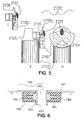
- FIG 5 illustrates a hard "nose” 2101 of for example hardened steel, chromium alloy, or for some applications a low-friction nose of PTFE plastic (polytetrafluorethane or "Teflon (TM)") which is attached to the centre of a partial guard 2102 attached beneath the abrading disk of an angle grinder 2103.
- the beneath view B depicts an aperture 2104 which is intended for the ejection of waste material - swarf and the like.
- the side view A shows a flat disk type of abrading disk 2105 which is provided with bristles, (not shown), presented to the edge 2106.
- the guard 2102 may be provided with a hinge and catch mechanism (not shown) so that it can flip open to allow the abrading disk to be cleaned or changed.
- Part C of this drawing shows an abrading disk 2108 having a dished profile and the adjacent nose 2101 and guard 2102. This presents a more nearly parallel alignment of tooth edges to a sheet of work material and is for example more suited to hand planing.
- This modification to provide a grinder system having rest means is not incompatible with the extra guard 1705 offered in Fig 17 for the upper surface of the disk.
- Perforations in the disk are provided in part so that the user can see the material to be abraded through the spinning disk as the tool working zone is drawn towards the user.
- the perforations are circular or at least have no sharp or narrow corners because of the risk of propagation of cracks from stressed areas. Holes 24 mm in diameter have been suitable.
- the holes are preferably equidistant from the centre but this arrangement is not essential.
- hole positions should be selected so as to retain the balance of the disk, and disks may be balanced dynamically by removing material from hole edges.
- the perforations may also aid in stirring the air so that any swarf is carried by the moving air and is ejected further or more effectively.
- the holes may be racked (drilled obliquely) or pitched. They may also be used as clamping points for a jig for alignment of the abrading disk in automated sharpening operations.
- Holes are a preferred option for the disks of the invention; providing visibility of the work about to be abraded, and aiding (especially if raked) in stirring and moving the air.
- the preferred embodiment has three equally spaced holes. Other combinations which place various holes at different distances from the centre may be used; although it is always preferable to maintain static and dynamic balance in rapidly rotating disks.
- FIG. 1 shows at 1900 a resilient central mount for a wheel 1901, having among other purposes the objective of minimising the effect of wheel imbalance on tool vibration.
- the resilient material (which is illustrated as 1906) is contained within a housing 1904 attached to the wheel, while a central threaded collar 1907 surrounding an aperture 1902 is attached to a fin 1905 running deeply into the resilient material, which is generally a type of rubber.
- the small gap may be at the outside, and the inner gap may be an interference fit.
- the fin 1905 may slip inside the further layer of metal.
- the base of the threaded collar (by 1907) serves as a nut to lock the wheel onto the arbor of the grinder.
- Fig. 7 shows at 2400 an alternative clutch and central resilient mount to that of Fig 6 for use with a tool base or disk.
- the clutch is designed to allow slippage when the torque applied to the tool is greater than a preset amount. It may include a "chatterbox" of some type to give an audible indication of slippage, and one way of providing this is to place several ball bearings 2402 between the disk and the resilient mount so that the balls click into or out recesses if the clutch slips.
- the portion of the resilient mount threaded onto the arbor of the angle grinder has a cone-shaped projection (as seen in section 2401) into the resilient material.
Landscapes
- Engineering & Computer Science (AREA)
- Mechanical Engineering (AREA)
- Polishing Bodies And Polishing Tools (AREA)
- Golf Clubs (AREA)
- Finish Polishing, Edge Sharpening, And Grinding By Specific Grinding Devices (AREA)
- Adornments (AREA)
- Walking Sticks, Umbrellas, And Fans (AREA)
- Dental Tools And Instruments Or Auxiliary Dental Instruments (AREA)
- Food-Manufacturing Devices (AREA)
- Toys (AREA)
Claims (9)
- Accessoire pour meuleuse comprenant un outil capable de tourner présentant un axe de rotation et étant muni d'une zone de travail s'étendant en-dedans à partir du périmètre de l'outil ; et des moyens d'appui situés radialement en-dedans de la zone de travail de l'outil et décalés à distance de la zone de travail le long de la ligne de l'axe de rotation de l'outil et en s'éloignant de la meuleuse, dans lequel la zone de travail de l'outil capable de tourner, est munie d'une pluralité de poils de brosserie capables de réaliser une action de découpe ou d'abrasion lorsqu'ils sont en mouvement de rotation, les poils de brosserie s'étendant à partir de la surface de la zone de travail et la longueur des poils de brosserie étant telle qu'une partie des moyens d'appui peut être mise en contact avec une surface de travail sans qu'un contact substantiel ne se produise entre les poils de brosserie et la surface de travail, caractérisé en ce que l'outil est en forme de disque et adapté pour être monté sur un arbre ou mandrin d'une meuleuse d'angle et en ce que la distance entre les moyens d'appui et la zone de travail est fixée.
- Accessoire selon la revendication 1, dans lequel les poils de brosserie sont formés à partir de fils métalliques.
- Accessoire selon la revendication 1, dans lequel les poils de brosserie sont situés dans une zone de travail s'étendant à partir du périmètre extérieur de l'outil en forme de disque jusqu'à un point qui va jusqu'aux deux tiers de la distance entre le périmètre et l'axe de rotation.
- Accessoire selon la revendication 1 dans lequel les poils de brosserie sont situés dans une zone de travail s'étendant à partir du périmètre extérieur de l'outil jusqu'à un point qui va jusqu'à un tiers de la distance entre le périmètre et l'axe de rotation.
- Accessoire selon la revendication 1, dans lequel les poils de brosserie sont situés dans deux ou plus de deux groupes espacés symétriquement les uns des autres autour de la zone de travail.
- Accessoire selon la revendication 1, dans lequel au moins une ouverture de vision est prévue à travers l'outil en forme de disque et dans lequel au moins une ouverture de vision peut, lorsque l'outil est en rotation, également servir à provoquer un mouvement d'air.
- Accessoire selon la revendication 1, comprenant un outil en forme de disque capable de tourner présentant une surface convexe ayant sa zone de travail obtenue par une portion périphérique extérieure de la surface convexe du disque qui présente des poils de brosserie situés dessus et dans lequel les moyens d'appui sont obtenue par une partie de la surface convexe du disque située à l'intérieur de la zone de travail.
- Meuleuse comprenant un accessoire selon la revendication 1, dans laquelle les moyens d'appui comprennent une protubérance fixée tournant avec l'accessoire.
- Meuleuse présentant une broche ("spindle") capable de tourner et comprenant un accessoire selon la revendication 1 dans laquelle les moyens d'appui comprennent une protubérance capable de tourner montée séparément au moyen d'un palier ("bearing") sur la broche capable de tourner de la meuleuse.
Applications Claiming Priority (3)
| Application Number | Priority Date | Filing Date | Title |
|---|---|---|---|
| NZ28029295 | 1995-10-19 | ||
| NZ280292A NZ280292A (en) | 1995-10-19 | 1995-10-19 | Accessory for angle grinder as rotatable annular tool with rest means for supporting grinder |
| PCT/US1996/016511 WO1997014538A1 (fr) | 1995-10-19 | 1996-10-15 | Outil a brosser adaptable sur une meuleuse d'angle |
Publications (2)
| Publication Number | Publication Date |
|---|---|
| EP0857099A1 EP0857099A1 (fr) | 1998-08-12 |
| EP0857099B1 true EP0857099B1 (fr) | 2000-03-15 |
Family
ID=19925513
Family Applications (2)
| Application Number | Title | Priority Date | Filing Date |
|---|---|---|---|
| EP96936521A Expired - Lifetime EP0857099B1 (fr) | 1995-10-19 | 1996-10-15 | Outil a brosser adaptable sur une meuleuse d'angle |
| EP96936514A Expired - Lifetime EP0855949B1 (fr) | 1995-10-19 | 1996-10-16 | Accessoires et pieces de fixation pour meule d'angle |
Family Applications After (1)
| Application Number | Title | Priority Date | Filing Date |
|---|---|---|---|
| EP96936514A Expired - Lifetime EP0855949B1 (fr) | 1995-10-19 | 1996-10-16 | Accessoires et pieces de fixation pour meule d'angle |
Country Status (9)
| Country | Link |
|---|---|
| EP (2) | EP0857099B1 (fr) |
| AT (2) | ATE190545T1 (fr) |
| AU (2) | AU695972B2 (fr) |
| DE (2) | DE69607194T2 (fr) |
| DK (2) | DK0857099T3 (fr) |
| ES (2) | ES2146909T3 (fr) |
| NZ (1) | NZ280292A (fr) |
| WO (2) | WO1997014538A1 (fr) |
| ZA (2) | ZA968396B (fr) |
Families Citing this family (2)
| Publication number | Priority date | Publication date | Assignee | Title |
|---|---|---|---|---|
| US6722955B2 (en) | 2001-01-10 | 2004-04-20 | 3M Innovative Properties Company | Buckup plate assembly for grinding system |
| JP2003145431A (ja) * | 2001-11-15 | 2003-05-20 | Riken Diamond Industry Co Ltd | ダイヤモンドカッターの製法 |
Family Cites Families (8)
| Publication number | Priority date | Publication date | Assignee | Title |
|---|---|---|---|---|
| US2740980A (en) * | 1953-02-25 | 1956-04-10 | Charles T Asbury | Apparatus for cutting and abrading |
| DE2502698A1 (de) * | 1975-01-23 | 1976-07-29 | Philippin Gmbh & Co Kg Ernst | Werkzeug zum entfernen von nicht festhaftenden stoffen, insbesondere einer grundierungsschicht, von dichtungsflaechen an heizkoerpern |
| DE3541348C1 (de) * | 1985-07-18 | 1987-01-02 | Gerd Eisenblaetter | Faecherstirnschleifscheibe |
| DE3539666C1 (de) * | 1985-11-08 | 1986-09-18 | RSA Entgrat-Technik Rainer Schmidt, 5880 Lüdenscheid | Motorisch angetriebene,handgefuehrte Maschine zum Entgraten,insbesondere von gelochten oder gestanzten Blechen |
| GB2207626A (en) * | 1987-08-04 | 1989-02-08 | Nippon Tenshashi Kk | Abrasive polishing element |
| US4835912A (en) * | 1987-11-30 | 1989-06-06 | Aleck Block | Abrasive wheel |
| DE9214144U1 (de) * | 1992-10-20 | 1992-12-10 | Chang, Jen Chih, Wu Jih Shzang, Taichung | Polierbürste mit Stahlborsten enthaltenden Poliereinheiten |
| EP0758286B1 (fr) * | 1994-05-03 | 2001-11-14 | Norton Company | Accessoire de meuleuse d'angle |
-
1995
- 1995-10-19 NZ NZ280292A patent/NZ280292A/xx not_active IP Right Cessation
-
1996
- 1996-10-04 ZA ZA968396A patent/ZA968396B/xx unknown
- 1996-10-09 ZA ZA968523A patent/ZA968523B/xx unknown
- 1996-10-15 DK DK96936521T patent/DK0857099T3/da active
- 1996-10-15 AT AT96936521T patent/ATE190545T1/de active
- 1996-10-15 DE DE69607194T patent/DE69607194T2/de not_active Expired - Lifetime
- 1996-10-15 ES ES96936521T patent/ES2146909T3/es not_active Expired - Lifetime
- 1996-10-15 EP EP96936521A patent/EP0857099B1/fr not_active Expired - Lifetime
- 1996-10-15 WO PCT/US1996/016511 patent/WO1997014538A1/fr active IP Right Grant
- 1996-10-15 AU AU74337/96A patent/AU695972B2/en not_active Ceased
- 1996-10-16 AT AT96936514T patent/ATE192685T1/de active
- 1996-10-16 WO PCT/US1996/016501 patent/WO1997014537A1/fr active IP Right Grant
- 1996-10-16 DK DK96936514T patent/DK0855949T3/da active
- 1996-10-16 ES ES96936514T patent/ES2149503T3/es not_active Expired - Lifetime
- 1996-10-16 DE DE69608293T patent/DE69608293T2/de not_active Expired - Lifetime
- 1996-10-16 EP EP96936514A patent/EP0855949B1/fr not_active Expired - Lifetime
- 1996-10-16 AU AU74329/96A patent/AU695973B2/en not_active Ceased
Also Published As
| Publication number | Publication date |
|---|---|
| ZA968396B (en) | 1997-05-13 |
| AU7432996A (en) | 1997-05-07 |
| ES2146909T3 (es) | 2000-08-16 |
| DK0857099T3 (da) | 2000-08-21 |
| ATE190545T1 (de) | 2000-04-15 |
| AU7433796A (en) | 1997-05-07 |
| WO1997014538A1 (fr) | 1997-04-24 |
| ES2149503T3 (es) | 2000-11-01 |
| DE69608293D1 (de) | 2000-06-15 |
| DE69607194T2 (de) | 2000-11-09 |
| EP0855949B1 (fr) | 2000-05-10 |
| AU695972B2 (en) | 1998-08-27 |
| WO1997014537A1 (fr) | 1997-04-24 |
| AU695973B2 (en) | 1998-08-27 |
| DE69608293T2 (de) | 2001-01-25 |
| ATE192685T1 (de) | 2000-05-15 |
| ZA968523B (en) | 1997-05-20 |
| NZ280292A (en) | 1999-11-29 |
| EP0855949A1 (fr) | 1998-08-05 |
| DE69607194D1 (de) | 2000-04-20 |
| DK0855949T3 (da) | 2000-10-02 |
| EP0857099A1 (fr) | 1998-08-12 |
Similar Documents
| Publication | Publication Date | Title |
|---|---|---|
| CA2187017C (fr) | Accessoire de machine a tailler angulairement dans un materiau | |
| US6280309B1 (en) | Accessories and attachments for angle grinder | |
| JP3479083B2 (ja) | 研磨ディスクの押え板 | |
| JP5036977B2 (ja) | ブラシユニット | |
| TW200800485A (en) | Oscillating grinding machine | |
| EP2103394A1 (fr) | Outil double action à transmission automatique | |
| EP0292246B1 (fr) | Outil pour travailler le bois | |
| US6173470B1 (en) | Brush attachment for grinder | |
| US6244947B1 (en) | Wire brush attachment for angle grinder | |
| EP0857099B1 (fr) | Outil a brosser adaptable sur une meuleuse d'angle | |
| US20020078813A1 (en) | Saw blade | |
| US5468178A (en) | Rotary device for removing paint from a surface | |
| JP2006020627A (ja) | 刈払い機用安全装置 | |
| JPH10179808A (ja) | ゴルフボールのバリ除去方法 | |
| JPS62259759A (ja) | 回転体を有する表面研削仕上装置 | |
| CA2380930C (fr) | Accessoire a brosse pour meuleuse | |
| JPH0618772Y2 (ja) | ハンドグラインダ | |
| JPH03154797A (ja) | 丸刃カッタとその製造装置および製造方法 | |
| US4491999A (en) | Buffing pad retainer | |
| US20210101248A1 (en) | Method and apparatus for forming holes | |
| JPH06226609A (ja) | バリ取り装置 | |
| WO1997038814A1 (fr) | Accessoire de ponçage rotatif | |
| JP2006000991A (ja) | 面取り装置 |
Legal Events
| Date | Code | Title | Description |
|---|---|---|---|
| PUAI | Public reference made under article 153(3) epc to a published international application that has entered the european phase |
Free format text: ORIGINAL CODE: 0009012 |
|
| 17P | Request for examination filed |
Effective date: 19980519 |
|
| AK | Designated contracting states |
Kind code of ref document: A1 Designated state(s): AT BE CH DE DK ES FR GB IT LI SE |
|
| GRAG | Despatch of communication of intention to grant |
Free format text: ORIGINAL CODE: EPIDOS AGRA |
|
| 17Q | First examination report despatched |
Effective date: 19990421 |
|
| GRAG | Despatch of communication of intention to grant |
Free format text: ORIGINAL CODE: EPIDOS AGRA |
|
| GRAH | Despatch of communication of intention to grant a patent |
Free format text: ORIGINAL CODE: EPIDOS IGRA |
|
| GRAH | Despatch of communication of intention to grant a patent |
Free format text: ORIGINAL CODE: EPIDOS IGRA |
|
| GRAA | (expected) grant |
Free format text: ORIGINAL CODE: 0009210 |
|
| AK | Designated contracting states |
Kind code of ref document: B1 Designated state(s): AT BE CH DE DK ES FR GB IT LI SE |
|
| REF | Corresponds to: |
Ref document number: 190545 Country of ref document: AT Date of ref document: 20000415 Kind code of ref document: T |
|
| REG | Reference to a national code |
Ref country code: CH Ref legal event code: EP |
|
| REF | Corresponds to: |
Ref document number: 69607194 Country of ref document: DE Date of ref document: 20000420 |
|
| ITF | It: translation for a ep patent filed | ||
| REG | Reference to a national code |
Ref country code: CH Ref legal event code: NV Representative=s name: BOVARD AG PATENTANWAELTE |
|
| ET | Fr: translation filed | ||
| REG | Reference to a national code |
Ref country code: ES Ref legal event code: FG2A Ref document number: 2146909 Country of ref document: ES Kind code of ref document: T3 |
|
| REG | Reference to a national code |
Ref country code: DK Ref legal event code: T3 |
|
| PLBE | No opposition filed within time limit |
Free format text: ORIGINAL CODE: 0009261 |
|
| STAA | Information on the status of an ep patent application or granted ep patent |
Free format text: STATUS: NO OPPOSITION FILED WITHIN TIME LIMIT |
|
| 26N | No opposition filed | ||
| REG | Reference to a national code |
Ref country code: GB Ref legal event code: IF02 |
|
| REG | Reference to a national code |
Ref country code: CH Ref legal event code: PFA Owner name: NORTON COMPANY Free format text: NORTON COMPANY#1 NEW BOND STREET, BOX NO. 15138#WORCESTER, MASSACHUSETTS 01615-0138 (US) -TRANSFER TO- NORTON COMPANY#1 NEW BOND STREET, BOX NO. 15138#WORCESTER, MASSACHUSETTS 01615-0138 (US) |
|
| PGFP | Annual fee paid to national office [announced via postgrant information from national office to epo] |
Ref country code: GB Payment date: 20130923 Year of fee payment: 18 |
|
| PGFP | Annual fee paid to national office [announced via postgrant information from national office to epo] |
Ref country code: AT Payment date: 20130923 Year of fee payment: 18 Ref country code: DE Payment date: 20130920 Year of fee payment: 18 Ref country code: FR Payment date: 20131028 Year of fee payment: 18 |
|
| REG | Reference to a national code |
Ref country code: DE Ref legal event code: R119 Ref document number: 69607194 Country of ref document: DE |
|
| REG | Reference to a national code |
Ref country code: AT Ref legal event code: MM01 Ref document number: 190545 Country of ref document: AT Kind code of ref document: T Effective date: 20141015 |
|
| GBPC | Gb: european patent ceased through non-payment of renewal fee |
Effective date: 20141015 |
|
| PG25 | Lapsed in a contracting state [announced via postgrant information from national office to epo] |
Ref country code: GB Free format text: LAPSE BECAUSE OF NON-PAYMENT OF DUE FEES Effective date: 20141015 Ref country code: DE Free format text: LAPSE BECAUSE OF NON-PAYMENT OF DUE FEES Effective date: 20150501 |
|
| REG | Reference to a national code |
Ref country code: FR Ref legal event code: ST Effective date: 20150630 |
|
| PG25 | Lapsed in a contracting state [announced via postgrant information from national office to epo] |
Ref country code: AT Free format text: LAPSE BECAUSE OF NON-PAYMENT OF DUE FEES Effective date: 20141015 Ref country code: FR Free format text: LAPSE BECAUSE OF NON-PAYMENT OF DUE FEES Effective date: 20141031 |
|
| PGFP | Annual fee paid to national office [announced via postgrant information from national office to epo] |
Ref country code: CH Payment date: 20150922 Year of fee payment: 20 |
|
| PGFP | Annual fee paid to national office [announced via postgrant information from national office to epo] |
Ref country code: SE Payment date: 20150925 Year of fee payment: 20 |
|
| PGFP | Annual fee paid to national office [announced via postgrant information from national office to epo] |
Ref country code: DK Payment date: 20150923 Year of fee payment: 20 |
|
| PGFP | Annual fee paid to national office [announced via postgrant information from national office to epo] |
Ref country code: IT Payment date: 20150925 Year of fee payment: 20 |
|
| PGFP | Annual fee paid to national office [announced via postgrant information from national office to epo] |
Ref country code: ES Payment date: 20151006 Year of fee payment: 20 Ref country code: BE Payment date: 20150924 Year of fee payment: 20 |
|
| REG | Reference to a national code |
Ref country code: DK Ref legal event code: EUP Effective date: 20161015 |
|
| REG | Reference to a national code |
Ref country code: CH Ref legal event code: PL |
|
| REG | Reference to a national code |
Ref country code: SE Ref legal event code: EUG |
|
| REG | Reference to a national code |
Ref country code: ES Ref legal event code: FD2A Effective date: 20170126 |
|
| PG25 | Lapsed in a contracting state [announced via postgrant information from national office to epo] |
Ref country code: ES Free format text: LAPSE BECAUSE OF EXPIRATION OF PROTECTION Effective date: 20161016 |