EP0855285B1 - Wickelkern - Google Patents
Wickelkern Download PDFInfo
- Publication number
- EP0855285B1 EP0855285B1 EP98300288A EP98300288A EP0855285B1 EP 0855285 B1 EP0855285 B1 EP 0855285B1 EP 98300288 A EP98300288 A EP 98300288A EP 98300288 A EP98300288 A EP 98300288A EP 0855285 B1 EP0855285 B1 EP 0855285B1
- Authority
- EP
- European Patent Office
- Prior art keywords
- engaging
- winding
- winding core
- core
- groove
- Prior art date
- Legal status (The legal status is an assumption and is not a legal conclusion. Google has not performed a legal analysis and makes no representation as to the accuracy of the status listed.)
- Expired - Lifetime
Links
- 238000004804 winding Methods 0.000 title claims description 192
- 238000003780 insertion Methods 0.000 claims description 25
- 230000037431 insertion Effects 0.000 claims description 25
- 230000002093 peripheral effect Effects 0.000 claims description 21
- 238000010276 construction Methods 0.000 description 5
- 239000000428 dust Substances 0.000 description 5
- 230000000694 effects Effects 0.000 description 5
- 239000000470 constituent Substances 0.000 description 3
- 230000006866 deterioration Effects 0.000 description 1
- 238000003754 machining Methods 0.000 description 1
- 238000004519 manufacturing process Methods 0.000 description 1
- 230000008018 melting Effects 0.000 description 1
- 238000002844 melting Methods 0.000 description 1
- 230000000717 retained effect Effects 0.000 description 1
- 238000000859 sublimation Methods 0.000 description 1
- 230000008022 sublimation Effects 0.000 description 1
Images


Classifications
-
- B—PERFORMING OPERATIONS; TRANSPORTING
- B41—PRINTING; LINING MACHINES; TYPEWRITERS; STAMPS
- B41J—TYPEWRITERS; SELECTIVE PRINTING MECHANISMS, i.e. MECHANISMS PRINTING OTHERWISE THAN FROM A FORME; CORRECTION OF TYPOGRAPHICAL ERRORS
- B41J33/00—Apparatus or arrangements for feeding ink ribbons or like character-size impression-transfer material
- B41J33/003—Ribbon spools
Definitions
- the present invention relates to a winding core and more particularly a winding core for winding up an ink ribbon accommodated rotatably within a ribbon cassette and having been used in printing.
- a thermal transfer printer has heretofore been used in which a predetermined paper is conveyed to between a platen and a thermal head as a recording means while being held between a conveying roller and a pressure roller which is brought into pressure contact with the conveying roller, then the thermal head is moved along the platen while it is kept in pressure contact with the platen through the paper, and heat generating elements of the thermal head are allowed to generate heat selectively in accordance with a recording signal while the ink ribbon is wound up to melt-transfer the ink of the ink ribbon onto the paper, thereby performing a desired recording on the paper.
- Fig. 10 is a perspective view showing a schematic construction of a carriage portion 23 of a conventional thermal transfer printer 21.
- a platen 22 in the shape of a flat plate is disposed near the central part of a frame (not shown) so that its printing surface is substantially perpendicular to the frame, a guide shaft 27 is disposed at a lower position in front of and in parallel with the platen 22, and a carriage 23 is mounted slidably on the guide shaft 27.
- a driving belt 28 entrained on a pair of pulleys (not shown) is driven by means of a stepping motor (not shown), whereby the carriage 23 is reciprocated on the guide shaft 27.
- a thermal head 24 is mounted on a front end portion of the carriage 23 in an opposed relation to the platen 22.
- the thermal head can move into contact with and away from the platen 22 through an appropriate mechanism.
- a ribbon cassette 26 (see Fig. 13 ) is loaded onto the upper surface of the carriage 23.
- the ribbon cassette 26 contains an ink ribbon 25 and conducts the ink ribbon to between the thermal head 24 and the platen 22.
- a winding mechanism 29 and a supply mechanism as constituents of an ink ribbon traveling mechanism to move the ink ribbon 25 in the direction of arrow A in the figure.
- the ink ribbon traveling mechanism will be further described below.
- the winding mechanism 29 has a winding shaft 30.
- the lower end portion of the winding shaft 30 is integrally formed with a support flange 32 projecting outward, and a winding gear 31 is loosely fitted on the said lower end portion in a rotatable manner independently of the winding shaft 30.
- a felt 33 is interposed between the underside of the winding gear 31 and the support flange 32 of the winding shaft 30 as a slip mechanism, while to the upper end portion of the winding shaft 30 is fixed a winding bobbin 35 which is exposed to the upper surface of the carriage 23 and engaged with a winding hole 34 formed in the ribbon cassette 26.
- an outer peripheral surface 36 of the winding bobbin 35 On an outer peripheral surface 36 of the winding bobbin 35 are formed three engaging projections 37 at circumferentially trisected positions, and an annular retaining groove 38 is formed in the lower surface of the winding bobbin 35.
- a biasing spring 39 On the outer periphery side of the winding shaft 30 is disposed a biasing spring 39 whose upper end portion is retained by the retaining groove of the winding bobbin 35 and whose lower end portion is abutted against the upper surface of the winding gear 32. With the biasing force of the biasing spring 39 the winding gear 32 is brought into pressure contact with the support flange 31 of the winding shaft 30 through the felt 33.
- a driving gear 40 fixed to a rotating shaft 48 of a winding motor 47 for the ink ribbon 25 is in mesh with the winding gear32.
- the driving gear 40 is rotated by operation of the ink ribbon winding motor 47 to thereby rotate the winding gear 32.
- This rotative driving force is transmitted to the winding shaft 30 by virtue of a frictional force of the felt 33 which is created by the biasing force of the spring 39 which is for urging the winding gear 32.
- the ribbon cassette 26 loaded onto the upper surface of the carriage 23 is constituted by a case body 41 which is generally rectangular in plan and which comprises a pair of upper case 41A and lower case 41B.
- a pair of cores 42, 42 supported rotatably, a pair of pinch rollers 43,43 also supported rotatably, and a plurality of guide rollers (not shown) supported rotatably and facing the ribbon traveling path.
- the paired cores 42, 42 are each formed in a generally cylindrical shape, and the ink ribbon 25, which has characteristics of heat sublimation or heat melting, is wound from both ends thereof on the outer peripheral surfaces of the cores 42, 42.
- the core 42located on the left-hand side in Fig. 13 is used as a winding core 42A for winding a portion of the ink ribbon 25 which portion has been used in recording, while the core 42 located on the right-hand side in the same figure is used as a supply core 42B for supply of the ink ribbon 26 in recording.
- each core 42 In an inner peripheral surface 44 of each core 42 are formed a plurality of engaging grooves 45, 45 in a spline shape spacedly in the circumferential direction.
- a winding hole 46A Inside of the inner peripheral surface 44 of the left-hand winding core 42A in Fig. 13 is used as a winding hole 46A for engagement therein of a winging bobbin 35A formed on the carriage 23 of the printer, while inside of the inner peripheral surface of the right-hand supply core 42B in Fig. 13 is used as a supply hole 46B for engagement therein of a delivery bobbin B which constitutes the foregoing supply mechanism.
- each conventional core 42 in the inner peripheral surface 44 of each conventional core 42 are merely formed a plurality of engaging grooves 45, 45 in a spline shape spacedly in the circumferential direction, so after loading of the ribbon cassette onto the carriage 23, dust gets into the engaging grooves 45, 45 from the upper openings, thus resulting in that rotation is not stable during winding of the ink ribbon 25 and the traveling of the ink ribbon becomes unstable, leading to deterioration of the print quality.
- the ribbon cassette 26 can be loaded onto the carriage 23 irrespective of the width of the ink ribbon 25 used, there has been the problem that an ink ribbon 25 of a narrow printing width is accommodated in the ribbon cassette 26.
- the above problems are not limited to between the winding bobbin 35 on the carriage 23 of the foregoing thermal transfer printer and the winding core 42A in the ribbon cassette 26 loaded on the carriage, but may occur also between a winding core in a cassette which receives therein a label printing tape or the like in a wound-up state and a winding bobbin formed on a body such as a label printer onto which the cassette is to be loaded.
- a winding core in a ribbon cassette which accommodates a web in a wound-up state
- the winding core having a plurality of engaging grooves formed circumferentially in its inner peripheral surface for engagement with a plurality of engaging projections formed circumferentially at equal intervals on an outer peripheral surface of a winding bobbin of a to-be-loaded body onto which the cassette is to be loaded
- the said engaging grooves each having side engaging portions for engagement with side faces of each said engaging projection and an upper engaging portion for engagement with an axial tip face of each said engaging projection in an abutted or ccvering relation thereto, thereby permitting the engaging projection to be engaged with the side engaging portions of each engaging groove firmly in the circumferential direction of the winding core, further permitting dust entry into the engaging grooves from above through the upper engaging portion in the axial direction of the winding core, wherein when a ribbon cassette containing a narrow ink ribbon for example and hence unsuitable for loading onto the to-be-loaded body is tried to be
- a winding core in a ribbon cassette wherein an engaging guide portion is contiguous to each of the side engaging portions of each engaging groove at an insertion- side end portion of the engaging groove, the engaging guide portion being formed as a slant face for causing each engaging projection of the winding bobbin to slide in a relative manner and guiding it into any of the engaging grooves of the winding core, thereby permitting the engaging projection to be easily guided into the engaging projection.
- winding core in a ribbon cassette wherein the plural engaging grooves formed in the inner peripheral surface of the winding core are connected together through the above engaging guide portions, whereby the engaging projections can be engaged with the engaging grooves through the engaging guide portions or directly.
- a winding core in a ribbon cassette wherein the engaging grooves are formed in such a manner that an engaging groove having an engaging groove insertion side at one axial end of the winding core and an engaging groove having an engaging groove insertion side at the opposite end of the winding core are alternately arranged circumferentially at equal intervals, whereby the ribbon cassette can be loaded from any axial side of the winding core relative to the winding bobbin.
- the invention may provide a winding core in a ribbon cassette wherein engaging guide portions which connect the insertion-side end portions of engaging grooves having insertion sides at the same end portion of the winding core also serve as the upper engaging portion of an engaging groove having an insertion side at the opposite end portion, whereby the winding core having such a waste-free shape can be loaded onto the winding bobbin from any axial side of the core.
- the engaging grooves are formed in the same number as the number of the engaging projections of the winding bobbin, the machining accuracy for the engaging grooves is improved and a stable traveling of an article accommodated in the ribbon cassette, such as ink ribbon, can be attained.
- the invention may provide a winding core in a ribbon cassette wherein, out of the side engaging portions of each engaging groove, the side engaging portion formed on the winding direction side of the winding core is shorter than the side engaging portion formed on the side opposite to the winding direction of the winding core, and the engaging guide portions are each formed as a slant face between the insertion-side end of a side engaging portion formed on the winding direction side of the winding core and the insertion-side end of a side engaging portion formed on the side opposite to the core winding direction of an adjacent engaging groove having an insertion side in the same direction, whereby the engaging projection abutted against the engaging guide portion can surely be guided to and engaged with the engaging groove formed on the winding direction side of the winding core.
- the invention may provide a winding core in a ribbon cassette wherein, out of the side engaging portions, the side engaging portion formed on the winding direction side of the winding core is shorter than the side engaging portion formed on the side opposite to the winding direction of the winding core, the engaging guide portion of each side engaging portion is formed at an insertion-side end of the side engaging portion so as to expand from the associated engaging groove, and a tip end of the engaging guide portion contiguous to the side engaging portion formed on the core winding direction side of each engaging groove is connected with a tip end of the engaging guide portion contiguous to the side engaging portion formed on the side opposite to the core winding direction of an adjacent engaging groove, whereby the engaging projection can be engaged with the engaging groove through the engaging guide portion or directly.
- the invention may provide a winding core in a ribbon cassette wherein the upper engaging portion of each engaging groove is in a steepled shape, whereby the engaging projection can be engaged with the engaging groove through the engaging guide portion or directly.
- Winding cores embodying the present invention will be described hereinunder with reference to Figs. 1 to 9.
- Fig. 1 is a developed view of an inner peripheral surface of a winding core according to the first embodiment of the present invention
- Fig. 2 is a plan view of the winding core
- Fig. 3 is a sectional view taken on line III-III in Fig. 2
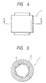
- Fig. 4 is a front view of the winding core
- Fig. 5 is a sectional view taken on line V-V in Fig. 4.
- the winding core of the first embodiment, indicated at 1 is formed generally in a cylindrical shape, and in an inner peripheral surface 2 of the winding core 1 are formed a plurality of engaging grooves 7 for engagement with a plurality of engaging projections 37 formed on an outer peripheral surface of a winding bobbin 35A circumferentially at equal intervals, the winding bobbin 35A being disposed on the carriage 23.
- the engaging grooves 7 are formed in such a manner that three engaging grooves having insertion sides on one axial end side of the winding core 1 and three engaging grooves 7 having insertion sides on the opposite end side are alternately formed in the inner peripheral surface 2 circumferentially at equal intervals.
- Each of the engaging grooves 7 has side engaging portions 8 for engagement of side faces of each engaging projection 37 and an upper engaging portion 9 for engagement with an axial tip face 11 of the engaging projection in an abutted or covering relation thereto.
- each side engaging portion 8 is formed an engaging guide portion 10 so as to expand from the engaging groove 7.
- the engaging guide portion 10 is formed as a slant face for causing the engaging projection 37 to slide in a relative manner into the engaging groove 7.
- Each engaging guide portion 10 comprises an engaging guide portion 10A contiguous to the winding-side side engaging portion 8A of each engaging groove 7 and an engaging guide portion 10B contiguous to the opposite-side side engaging portion 8B of an adjacent engaging groove 7 having an insertion side in the same direction.
- the tip end of the engaging guide portion 10A is connected with the tip end of the engaging guide portion 10B.
- the upper engaging portion 9 is formed in a steepled shape projecting axially upward in conformity with the shape generally adopted as the shape of axial tip face 11 of each engaging projection 37 formed on the winding bobbin 35A.
- the upper engaging projection 9 is formed in abutment with or along and spacedly from the axial tip face 11 of the engaging projection 37 to cover the tip face 11.
- the slant face of the engaging guide portion 10A contiguous to the winding- side engaging portion 8A shorter than the opposite-side side engaging portion 8B is formed long, while the slant face of the engaging guide portion 10B contiguous to the opposite-side side engaging portion 8B is formed short.
- the length of the engaging guide portion 10B is almost equal to that of one side which constitutes the upper engaging portion 9, and the above connection is in a steepled shape projecting axially downward.
- each engaging groove 7 of the winding core 1 thus formed, the area of the portion (indicated with cross hatches in Fig. 1) sandwiched between the winding-side side engaging portion 8A of each engaging groove 7 and the winding-side side engaging portion 8A of an adjacent engaging groove 7 having an insertion side on the axially opposite end side of the winding core 1 is set larger than the area of the portion sandwiched between the opposite-side side engaging portion 8B of each engaging groove 7 and the opposite-side side engaging portion 8B of an adjacent engaging groove 7 having an insertion side on the axially opposite end side of the winding core 1.
- the loading is tried in a somewhat deviated state between the position of the engaging groove 7 and the engaging projection 37.
- the tip of the engaging projection 37 first abuts the engaging guide portion 10 formed on the core 1 and slides in a relative manner along a slant face of the engaging guide portion 10, resulting in engagement thereof with the engaging groove 7.
- the engaging projections 37 formed on the winding bobbin 35A can be surely conducted and engaged with the engaging grooves 7 formed in the winding core 1.
- the engaging guide portion 10B which is formed at an end of the opposite-side side engaging portion 8B so as to expand from the engaging groove7, is short, the possibility of the engaging projection 37 coming into abutment against the engaging guide portion 10A, which is formed at an end of the winding-side side engaging portion 8A so as to expand from the engaging groove 7, or coming into direct engagement with the engaging groove 7 is higher than the possibility of the engaging projection 37 coming into abutment against the engaging guide portion 10B.
- the winding core 1 rotates in the direction opposite to the winding direction of the accommodated web such as ink ribbon onto the winding core 1.
- the rotation is only to a slight distance (in this embodiment only half of the circumferential width of the engaging projection 37), the wound-up web is not slackened to such an extent as causes an obstacle to use.
- the engaging projection 37 engaged with each engaging groove 7 is sideways abutted on its winding direction side against the winding-side side engaging portion 8A to effect the transfer of a rotating force.
- Fig. 6 is a perspective view showing a state in which an engaging projection of the winding bobbin 37 is engaged with an engaging groove 7 of the winding core 1.
- the side engaging portions 8 are engaged with both circumferential side faces of the engaging projection 37, while the upper engaging portion 9 is positioned along the axial tip face 11 of the engaging projection 37 so as to cover the tip face 11.
- the cassette 26 contains, for example, a ribbon of a small width and is therefore unsuitable for loading onto the body to be loaded, and when an attempt is made to load such an unsuitable cassette 26 onto the body to be loaded, the upper engaging portion 9 in the winding core 1 of the cassette 26 side comes into abutment against the upper portion of the engaging projection on the winding bobbin 35A side, so that a further entry is inhibited and thus an inappropriate cassette loading can be prevented.
- an engaging groove 7 having an insertion side on one axial end side of the winding core 1 and an engaging groove 7 having an insertion side on the opposite end side are alternately arranged circumferentially at equal intervals, so by turning the cassette 26 having the winding core 1 upside down in the axial direction of the winding core, it is made possible to use both sides of the cassette 26.
- the winding core 1 disposed in the cassette is required to function also as a deliver-side core.
- the core can be designated the winding core 1.
- an ink ribbon cassette 26 in a printer is sometimes required to be employable on both sides thereof and in this case it is desirable to use the winding core 1 of this embodiment.
- Fig. 7 is a developed view of an inner peripheral surface of a winding core according to the second embodiment of the present invention.
- engaging grooves 7 are formed in the winding core indicated at 1 circumferentially at equal intervals in such a manner that each engaging groove 7 has its insertion side on only one axial end side of the winding core 1.
- the engaging grooves 7 may be connected together through engaging guide portions 10 in the same way as in the previous embodiment. Even in this case there can be attained the foregoing effects except that it is impossible to use both sides of the cassette 26.
- the cassette 26 using such a winding core 1 premises the use of only one side thereof. In this case, as to the case on the delivery side, it is not limited to such a core as that of the present invention, but a conventional core may be used.
- Fig. 8 is a developed view of a winding core 1 according to the third embodiment of the present invention, in which engaging guide portions 10 which connect insertion-side ends of engaging grooves 7 having their insertion sides at the same end portion of the winding core 1 and an upper engaging portion 9 of an engaging groove 7 having aninsertion side at the opposite end portion are not allowed to function as a combination thereof but are formed as separate portions.
- the upper engaging portion is formed in a shape of circular arc.
- the winding core 1 of this embodiment can also affords the same effects as in the previous embodiments.
- the engaging grooves 7 may be formed in such a manner that the insertion sides of engaging projections 37 are alternately positioned at both axial ends of the winding core 1.
- Fig. 9 is a developed view of a winding core 1 according to the fourth embodiment of the present invention.
- a winding-side side engaging portion 8A as a constituent portion of each engaging groove 7 formed in an inner peripheral surface 2 of the winding core is formed shorter than an opposite-side side engaging portion 8B as a constituent portion of the engaging groove 11.
- An engaging guide portion 10 is formed as a slant face between an insertion-side end of the winding-side side engaging portion 8A and that of the opposite-side side engaging portion 8B of an adjacent engaging groove 7 having its insertion side in the same direction.
- an upper engaging portion 9 of each engaging groove 7 is formed in conformity with the slant shape of the engaging guide portion 10 so that it can also function as the engaging guide portion 10.
- the winding core 1 When each engaging projection 37 slides on the engaging guide portion 10 into engagement with the engaging groove 7, the winding core 1 is sure to rotate in the direction to wind up thereon a web-like accommodated article such as ink ribbon located on the outer peripheral surface of the core. Consequently, an extra slack of the web is eliminated and the cassette 26 having the winding core 1 is used in a good condition. It is needless to say that the foregoing effects can also be attained such as inexpensive manufacture and easy and reliable engagement of each engaging projection 37 into the engaging groove 7.
- the engaging grooves 7 may be formed in such a manner that the insertion sides of engaging projections 37 are alternately positioned at both axial ends of the winding core 1.
- the cassette can be loaded onto the carriage in a slack-free good condition of the web accommodated in the cassette. Besides, it is possible to prevent the entry of dust into the engaging grooves after the loading of the cassette and it is possible effect loading of only such a cassette as is suitable for the loading.
Landscapes
- Impression-Transfer Materials And Handling Thereof (AREA)
- Storage Of Web-Like Or Filamentary Materials (AREA)
Claims (8)
- Spule einer Bandkassette, in der ein langes Farbband von seinen beiden Enden her aufgewickelt ist und in der, gegeneinander wirkend, eine Spule zum Auf- und eine Spule zum Abwickeln vorgesehen sind, die jeweils drehbar in einem Hauptgehäuse gehalten werden;die Kassette kann, auf einem Trägerschlitten eines Wärmetransferdruckers angebracht, verwendet werden,wobei an einer inneren Umfangsfläche der Spule in Umfangsrichtung mehrere Kupplungsschlitze ausgebildet sind, in die bei auf dem Trägerschlitten angebrachter Kassette mehrere Kupplungsnasen eingreifen, die an einer äußeren Umfangsfläche eines auf dem Schlitten angeordneten Spulkopfes ausgebildet sind, unddie Kupplungsschlitze an ihren Seitenflächen Angriffsabschnitte aufweisen, an denen die Seitenflächen der Kupplungsnasen des Spulkopfes angreifen, und obere Angriffsabschnitte, die an den äußersten axialen Endflächen der Kupplungsnasen des Spulkopfs angreifen und anstoßen oder diese abdecken.
- Spule einer Bandkassette, bei der das Einsteckende des Spulkopfs und der Kupplungsschlitz jedes Seitenflächen-Angriffsabschnitts zusammenwirkend mit Führungsabschnitten angeordnet sind, die aus geneigten Flächen gebildet werden, an denen die Kupplungsnasen des Spulkopfs entlanggleiten und die sie in einen der Kupplungsschlitze führen.
- Spule nach Anspruch 2, wobei die Kupplungsschlitze, die an der inneren Außenfläche der Spule ausgebildet sind, über die Führungsabschnitte miteinander verbunden sind.
- Spule nach Anspruch 2, wobei die Kupplungsschlitze so ausgebildet sind, daß ein Kupplungsschlitz, der an einem axialen Ende der Spule eine Einsteckseite aufweist, und ein Kupplungsschlitz, der am gegenüberliegenden Ende der Spule eine Einsteckseite aufweist, abwechselnd in gleichen Abständen über den Umfang verteilt angeordnet sind.
- Spule nach Anspruch 4, wobei die Führungsabschnitte, die die einsteckseitigen Endabschnitte der Kupplungsschlitze mit Einsteckseiten am gleichen Ende der Spule miteinander verbinden, gleichzeitig als obere Angriffsabschnitte eines Kupplungsschlitzes mit der Einsteckseite am gegenüberliegenden Spulenende dienen.
- Spule nach Anspruch 3, wobei von den Seitenangriffsabschnitten jedes Kupplungsschlitzes der Seiteneingriffsabschnitt, der an der in Wickelrichtung liegenden Seite der Spule ausgebildet ist, kürzer ist, als der Seitenangriffsabschnitt, der an der der Wickelrichtung gegenüberliegenden Seite der Spule liegt, und
die Führungsabschnitte jeweils als geneigte Fläche zwischen dem einsteckseitigen Ende eines in Wickelrichtung der Spule ausgebildeten Seitenangriffsabschnitts und dem einsteckseitigen Ende eines Seitenangriffsabschnitts ausgebildet sind, der an der der Wickelrichtung des Kerns gegenüberliegenden Seite eines angrenzenden Eingriffsschlitzes ausgebildet ist und eine in die gleiche Richtung weisende Einsteckseite hat. - Spule nach Anspruch 3, wobei von den Seitenangriffsabschnitten der Seitenangriffsabschnitt, der an der in Wickelrichtung liegenden Seite der Spule ausgebildet ist, kürzer ist als der Seitenangriffsabschnitt, der an der der Wickelrichtung gegenüberliegenden Seite der Spule ausgebildet ist,
der Führungsabschnitt jedes Seitenangriffsabschnitts so an dem einsteckseitigen Ende des Seitenangriffsabschnitts ausgebildet ist, daß er sich vom zugehörigen Kupplungsschlitz aus erstreckt, und ein Spitzenende des Führungsabschnitts, der an den auf der in Wickelrichtung liegenden Seite des Kerns ausgebildeten Seitenangriffsabschnitt angrenzt, mit einem Spitzenende des Führungsabschnitts verbunden ist, der an den Seitenangriffsabschnitt angrenzt, der auf der gegen die Wickelrichtung liegenden Seite eines angrenzenden Kupplungsschlitzes angeordnet ist. - Spule nach Anspruch 7, wobei der obere Angriffsabschnitt jedes Kupplungsschlitzes steil geneigt verläuft.
Applications Claiming Priority (3)
| Application Number | Priority Date | Filing Date | Title |
|---|---|---|---|
| JP1020297 | 1997-01-23 | ||
| JP9010202A JPH10203732A (ja) | 1997-01-23 | 1997-01-23 | 巻取りコア |
| JP10202/97 | 1997-01-23 |
Publications (2)
| Publication Number | Publication Date |
|---|---|
| EP0855285A1 EP0855285A1 (de) | 1998-07-29 |
| EP0855285B1 true EP0855285B1 (de) | 2001-07-25 |
Family
ID=11743698
Family Applications (1)
| Application Number | Title | Priority Date | Filing Date |
|---|---|---|---|
| EP98300288A Expired - Lifetime EP0855285B1 (de) | 1997-01-23 | 1998-01-15 | Wickelkern |
Country Status (5)
| Country | Link |
|---|---|
| US (1) | US5931588A (de) |
| EP (1) | EP0855285B1 (de) |
| JP (1) | JPH10203732A (de) |
| CN (1) | CN1081133C (de) |
| DE (1) | DE69801169T2 (de) |
Families Citing this family (2)
| Publication number | Priority date | Publication date | Assignee | Title |
|---|---|---|---|---|
| JP2001224663A (ja) * | 2000-02-15 | 2001-08-21 | Sanyo Electric Co Ltd | 固形製剤包装装置及び固形製剤用包装紙ロール |
| JP6297514B2 (ja) | 2015-03-19 | 2018-03-20 | セイコーエプソン株式会社 | テープカートリッジ |
Family Cites Families (8)
| Publication number | Priority date | Publication date | Assignee | Title |
|---|---|---|---|---|
| US2954701A (en) * | 1957-11-27 | 1960-10-04 | Solfred Maizus | Electro magnetic actuator |
| DE8113901U1 (de) * | 1981-05-12 | 1981-09-17 | Triumph-Adler Aktiengesellschaft für Büro- und Informationstechnik, 8500 Nürnberg | Mitnehmerkupplung für die Antriebsvorrichtung von Farbbändern in Schreib- und ähnlichen Maschinen |
| JPS60109957U (ja) * | 1983-12-28 | 1985-07-25 | 富士化学紙工業株式会社 | タイプライタ−におけるリ−ル巻修正テ−プ |
| JPH0143267Y2 (de) * | 1984-11-20 | 1989-12-15 | ||
| US4610555A (en) * | 1984-12-20 | 1986-09-09 | Eugene Di Luco | Universal ribbon spool for typewriters and other machines |
| US5096315A (en) * | 1989-02-02 | 1992-03-17 | Alps Electric Co., Ltd. | Ink ribbon winding mechanism |
| JPH058524A (ja) * | 1991-07-04 | 1993-01-19 | Sharp Corp | テープ巻取装置 |
| US5326182A (en) * | 1992-09-14 | 1994-07-05 | Datamax Bar Code Products Corporation | Ribbon roll drive |
-
1997
- 1997-01-23 JP JP9010202A patent/JPH10203732A/ja not_active Withdrawn
-
1998
- 1998-01-15 EP EP98300288A patent/EP0855285B1/de not_active Expired - Lifetime
- 1998-01-15 DE DE69801169T patent/DE69801169T2/de not_active Expired - Fee Related
- 1998-01-21 US US09/010,266 patent/US5931588A/en not_active Expired - Fee Related
- 1998-01-23 CN CN98100381A patent/CN1081133C/zh not_active Expired - Fee Related
Also Published As
| Publication number | Publication date |
|---|---|
| DE69801169D1 (de) | 2001-08-30 |
| EP0855285A1 (de) | 1998-07-29 |
| CN1191810A (zh) | 1998-09-02 |
| US5931588A (en) | 1999-08-03 |
| DE69801169T2 (de) | 2002-03-14 |
| JPH10203732A (ja) | 1998-08-04 |
| CN1081133C (zh) | 2002-03-20 |
Similar Documents
| Publication | Publication Date | Title |
|---|---|---|
| JPH07329385A (ja) | インクフィルムカセット | |
| EP0036308B1 (de) | Patrone für ein Farbband für einen Schlagdrucker | |
| EP0855285B1 (de) | Wickelkern | |
| JPH09272250A (ja) | テープリール装置およびこれを備えたテープカートリッジ | |
| US5476330A (en) | Ink ribbon cassette for thermal transfer printer | |
| JPH0357680A (ja) | 熱転写プリンタのカラーリボン頭出し方法 | |
| JP3398288B2 (ja) | リボンカセット | |
| US6398360B1 (en) | Thermal printer using a split rotary platen to print on different widths of paper | |
| US4772144A (en) | Ribbon cartridge having removable capstan | |
| US6039477A (en) | Ink ribbon take-up mechanism having transfer member | |
| JP3095632B2 (ja) | 熱転写プリンタ | |
| KR970064958A (ko) | 열전사 프린터 | |
| KR890003355Y1 (ko) | 열감응 프린터 | |
| JP3121725B2 (ja) | 熱転写プリンタ | |
| JP3095631B2 (ja) | 熱転写プリンタ | |
| JPH09202024A (ja) | ピンチローラおよびその製造方法ならびにリボンカセット | |
| US5988901A (en) | Ribbon cassette and pancake accommodated in the ribbon cassette | |
| JPH10193756A (ja) | リボンカセット | |
| JP3046720B2 (ja) | 熱転写プリンタ | |
| JPH0648004A (ja) | リボンカセット | |
| JP2001030594A (ja) | インクリボンカセットの支持構造 | |
| JP3058553B2 (ja) | インクリボンカセット | |
| JP3095630B2 (ja) | 熱転写プリンタ | |
| JPS61195879A (ja) | インクリボンカセツト | |
| JPH0648003A (ja) | リボンカセットおよびこれを用いた熱転写プリンタ |
Legal Events
| Date | Code | Title | Description |
|---|---|---|---|
| PUAI | Public reference made under article 153(3) epc to a published international application that has entered the european phase |
Free format text: ORIGINAL CODE: 0009012 |
|
| AK | Designated contracting states |
Kind code of ref document: A1 Designated state(s): DE FR GB |
|
| AX | Request for extension of the european patent |
Free format text: AL;LT;LV;MK;RO;SI |
|
| 17P | Request for examination filed |
Effective date: 19980602 |
|
| AKX | Designation fees paid |
Free format text: DE FR GB |
|
| RBV | Designated contracting states (corrected) |
Designated state(s): DE FR GB |
|
| 17Q | First examination report despatched |
Effective date: 19990720 |
|
| GRAG | Despatch of communication of intention to grant |
Free format text: ORIGINAL CODE: EPIDOS AGRA |
|
| GRAG | Despatch of communication of intention to grant |
Free format text: ORIGINAL CODE: EPIDOS AGRA |
|
| GRAH | Despatch of communication of intention to grant a patent |
Free format text: ORIGINAL CODE: EPIDOS IGRA |
|
| GRAH | Despatch of communication of intention to grant a patent |
Free format text: ORIGINAL CODE: EPIDOS IGRA |
|
| GRAA | (expected) grant |
Free format text: ORIGINAL CODE: 0009210 |
|
| AK | Designated contracting states |
Kind code of ref document: B1 Designated state(s): DE FR GB |
|
| REF | Corresponds to: |
Ref document number: 69801169 Country of ref document: DE Date of ref document: 20010830 |
|
| ET | Fr: translation filed | ||
| REG | Reference to a national code |
Ref country code: GB Ref legal event code: IF02 |
|
| PGFP | Annual fee paid to national office [announced via postgrant information from national office to epo] |
Ref country code: GB Payment date: 20020128 Year of fee payment: 5 |
|
| PGFP | Annual fee paid to national office [announced via postgrant information from national office to epo] |
Ref country code: FR Payment date: 20020129 Year of fee payment: 5 |
|
| PLBE | No opposition filed within time limit |
Free format text: ORIGINAL CODE: 0009261 |
|
| STAA | Information on the status of an ep patent application or granted ep patent |
Free format text: STATUS: NO OPPOSITION FILED WITHIN TIME LIMIT |
|
| 26N | No opposition filed | ||
| PG25 | Lapsed in a contracting state [announced via postgrant information from national office to epo] |
Ref country code: GB Free format text: LAPSE BECAUSE OF NON-PAYMENT OF DUE FEES Effective date: 20030115 |
|
| GBPC | Gb: european patent ceased through non-payment of renewal fee | ||
| PG25 | Lapsed in a contracting state [announced via postgrant information from national office to epo] |
Ref country code: FR Free format text: LAPSE BECAUSE OF NON-PAYMENT OF DUE FEES Effective date: 20030930 |
|
| REG | Reference to a national code |
Ref country code: FR Ref legal event code: ST |
|
| PGFP | Annual fee paid to national office [announced via postgrant information from national office to epo] |
Ref country code: DE Payment date: 20050317 Year of fee payment: 8 |
|
| PG25 | Lapsed in a contracting state [announced via postgrant information from national office to epo] |
Ref country code: DE Free format text: LAPSE BECAUSE OF NON-PAYMENT OF DUE FEES Effective date: 20060801 |