EP0855281A2 - Tragbarer Drucker mit Schnittstelle zur Annahme einer externen Versorgungsspannung - Google Patents
Tragbarer Drucker mit Schnittstelle zur Annahme einer externen Versorgungsspannung Download PDFInfo
- Publication number
- EP0855281A2 EP0855281A2 EP98300474A EP98300474A EP0855281A2 EP 0855281 A2 EP0855281 A2 EP 0855281A2 EP 98300474 A EP98300474 A EP 98300474A EP 98300474 A EP98300474 A EP 98300474A EP 0855281 A2 EP0855281 A2 EP 0855281A2
- Authority
- EP
- European Patent Office
- Prior art keywords
- portable printer
- interface
- unit
- power
- Prior art date
- Legal status (The legal status is an assumption and is not a legal conclusion. Google has not performed a legal analysis and makes no representation as to the accuracy of the status listed.)
- Withdrawn
Links
Images


Classifications
-
- B—PERFORMING OPERATIONS; TRANSPORTING
- B41—PRINTING; LINING MACHINES; TYPEWRITERS; STAMPS
- B41J—TYPEWRITERS; SELECTIVE PRINTING MECHANISMS, i.e. MECHANISMS PRINTING OTHERWISE THAN FROM A FORME; CORRECTION OF TYPOGRAPHICAL ERRORS
- B41J3/00—Typewriters or selective printing or marking mechanisms characterised by the purpose for which they are constructed
- B41J3/36—Typewriters or selective printing or marking mechanisms characterised by the purpose for which they are constructed for portability, i.e. hand-held printers or laptop printers
Definitions
- the present invention relates to a portable printer.
- Portable printers have been produced that are similar to stationary printers, but are smaller and lighter weight.
- Portable printers are configured to be driven by a power supply unit, such as a rechargeable primary or secondary cell, so that they can be used even where no AC power supply is available.
- a power supply unit such as a rechargeable primary or secondary cell
- a portable printer includes: an interface unit connectable to an external device to receive power and print information from the external device; a memory unit that stores the print information; a recording unit that forms images on a recording medium; and a control unit for controlling the recording unit to print an image according to the print information stored in the memory unit.
- a printer may be provided including an interface for simultaneously supplying power and print information from an external computer.
- the portable printer is driven by power supplied via the interface unit.
- Print information is also received via the same interface and is stored in the memory unit.
- the control unit controls the print unit to print on the print medium according to the print information stored in the memory unit, for example, by scanning across the surface of the print medium.
- the portable printer is capable of simultaneously receiving power and print information from an external computer via a single interface unit. Accordingly, power for driving the portable printer can be supplied from the power source of the external computer. Therefore, there is no need for the user to provide a separate AC adapter for the portable printer.
- the interface unit conforms to PCMCIA standards. Therefore, it can be easily electrically connected to an external computer.
- the interface unit could be any type of interface capable of supplying power as well as print information.
- the interface unit could be a Centronics interface, an USB interface, or an IEEE1394 interface.
- a power storage unit for supplying power to various components of the portable printer. Therefore, the portable printer can be operated even when it is disconnected from the external computer. Also, power supplied from the external computer via the interface unit is stored in the power storage unit so that power drawn from the power storage unit while the portable printer is disconnected from the portable computer can be replenished while the portable printer is connected to the portable computer.
- the recording unit is an ink jet type recording unit that ejects ink to print. Therefore, printing is performed without the recording unit contacting the print medium so that good printing results can be obtained even when the print surface is not flat. Further, compared to a recording unit that requires, for example, a print ribbon, the configuration is simpler so that the overall device can be made smaller. Also, printed images are clearer.
- a piezoelectric type ink jet head which has low power consumption, is used as the recording unit. Therefore, the load on the power source of the computer can be kept low when printing using the portable printer.
- Fig. 1 is a perspective view showing external configuration of a portable printer 3 according to the present embodiment of the invention and a portable computer 1 connected to the portable printer 3.
- the portable computer 1 includes a card slot 2 conforming to PCMCIA standards.
- the card slot 2 includes a power source pin and data transmission pins.
- the power source pin is for supplying power to, for example, the LSI provided in a LAN card or a modem card, and also to the portable printer 3 in a manner to be described below.
- the portable printer 3 has a slender tubular casing 9. At an upper surface of the casing 9 is provided a power switch 51 for turning on and off a power source of the portable printer 3, an online switch 52, and a liquid crystal display (LCD) 53 for displaying various conditions of the printer.
- An opening portion 6a is formed in the upper surface of the casing 9.
- a sheet supply port 6b is formed in a side surface of the casing 9.
- An interface card 4 is connected to the portable printer 3 via a cable 5.
- the interface card 4 is configured into a shape insertable into the card slot 2 and includes connector elements that connect to the power supply pin and to the data transmission pins of the card slot 2 when the interface card 4 is inserted into the card slot 2.
- the portable printer 3 becomes electrically connected to the portable computer 1 by insertion of the interface card 4 into the card slot 2 so that the interface card 4 can simultaneously perform both supply of power and transmission of image information, such as print data, between the portable computer 1 and the portable printer 3.
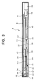
- Figs. 2 and 3 show internal configuration of the portable printer 3 according to the embodiment.
- Fig. 2 is a top cross-sectional view and
- Fig. 3 is a side cross-sectional view of the portable printer.
- the casing 9 houses a carriage 7, a carriage movement mechanism, a sheet transport mechanism.
- the carriage 7 is mounted in the opening portion 6a and an ink jet head 10 is mounted on the carriage 7.
- the sheet transport mechanism is for transporting print sheets from the sheet supply port 6b in a sheet transport direction.
- the carriage movement mechanism is for reciprocally moving the carriage 7 through a space 8 in a direction substantially perpendicular to the sheet transport direction in a range corresponding to the size of the print sheet.
- the ink jet head 10 be formed from a piezoelectric type ink jet head because piezoelectric type ink jet heads have much lower power consumption than other types of print heads, such as thermal type print heads.
- a thermal type print head requires about 60.00 mJ of power to print each character, but an ink jet type print head requires only 0.14 mJ of power to print each character.
- the transport mechanism is disposed in the casing 9 at the left-hand side thereof as viewed in Figs. 2 and 3.
- the transport mechanism includes transport rollers 21, each disposed on a rotational shaft 21a.
- the transport mechanism includes two transport rollers 21 as shown in Fig. 2, to facilitate explanation, only one of the transport rollers 21 and related configuration thereof will be described below while referring to Fig. 3.
- the transport roller 21 is rotatably supported on the casing 9 by bearings 22, 22 and is for transporting the print sheet. Although the transport roller 21 is shifted to the left of the center position of the casing 9 as viewed in Fig. 3, it is positioned near the substantial center of print sheets to be transported.
- the transport mechanism further includes: a gear 23 fixed on the rotational shaft 21a; a driving gear 26 connected with the gear 23 via an idle gear 24 so that rotation of the driving gear 26 rotates the gear 23; and a pulse motor 25 for driving rotation of the driving gear 26.
- Supplementary rollers 28, 28 are disposed in confrontation with the transport roller 21 on a rotational shaft 29.
- the rotational shaft 21a is rotatably supported on a bearing member 35 at one end and on a connection member 31 at the other end.
- a coil spring 34 is disposed between the connection member 31 and the left side of the casing 9 so as to constantly urge the supplementary rollers 28, 28 into contact with the transport roller 21. With this configuration, the supplementary rollers 28, 28 support sheets in contact with the transport roller 21, thereby supplementing transport operations performed by the transport roller 21.
- the transport mechanism configured in this manner transports print sheets supplied through the sheet supply port 6b in a direction perpendicular to the direction of reciprocal movement of the carriage 7. After printing has been performed by the ink jet head 10 mounted on the carriage 7, the transport mechanism discharges the print sheet from a sheet discharge port not shown in the drawings.
- Circuit boards 42 are disposed in parallel with each other between the pulse motor 16 and the transport mechanism.
- the circuit boards 42 include control circuitry for controlling the transport mechanism and the carriage movement mechanism in order to print images and the like.
- a rechargeable battery 20 is provided next to the circuit boards 42.
- a flexible cable 41 is provided to electrically connect the ink jet head 10 with the circuit boards 42.
- Fig. 4 is a block diagram showing the electrical configuration of the portable printer 3 according to the present embodiment.
- the portable printer 3 includes a variety of electrical components connected together, such as a CPU 60; a ROM 61 for storing a control program file for controlling the various electrical components of the portable printer 3; a RAM 62 for storing print data and the like; an LCD control portion 66 for controlling display of the LCD 53; a head drive portion 65 for controlling drive of the ink jet head 10; a motor controller portion 67 for controlling the pulse motors 16, 25; a power control portion 64 for performing a variety of actions such as monitoring residual amount of charge in the battery and controlling recharge of the rechargeable battery 20; and a PCMCIA interface control portion 63.
- a CPU 60 central processing unit 60
- a ROM 61 for storing a control program file for controlling the various electrical components of the portable printer 3
- a RAM 62 for storing print data and the like
- an LCD control portion 66 for controlling display of the LCD 53
- a head drive portion 65 for controlling drive of the ink jet head 10
- a motor controller portion 67 for controlling the pulse motors 16,
- the CPU 60, the ROM 61, the RAM 62, the head drive portion 65, the LCD control portion 66, the motor controller portion 67, and the power control portion 64 are mounted on the circuit boards 42.
- the portable printer 3 is used with the interface card 4 inserted in the card slot 2 of the portable computer 1.
- the portable computer 1 can supply power to the portable printer 3.
- the portable printer 3 will enter an operable condition.
- the power control portion 64 supplies power from the portable computer 1 to the circuit boards 42 and to various motors of the portable printer 3 and also, while monitoring the residual amount of charge in the rechargeable battery 20, recharges the rechargeable battery 20. It should be noted, when the interface card 4 is not inserted in the card slot 2, the power source control portion 64 supplies electrical energy from the battery 20 to the circuit boards 42 and to the motors.
- the portable computer 1 When the user wishes to print out text and the like prepared using the portable computer 1, he or she indicates this desire to the portable computer 1, which accordingly outputs a print command to the portable printer 3 to execute printing operations.
- the portable computer 1 outputs print data, which is transmitted through the PCMCIA interface control portion 63 and stored in the RAM 62.
- the CPU 60 commands the motor controller portion 67 to drive the pulse motor 16 in its forward rotational direction to move the carriage 7.
- the CPU 60 drives the head drive portion 65 according to the print data stored in the RAM 62 so that the ink jet head 10 ejects ink to print. Printing continues until a single line of print has been completed.
- the pulse motor 16 When a single line of print has been printed, the pulse motor 16 is driven in its reverse rotational direction so that the carriage 7 is returned to its starting position. Then, the pulse motor 25 is driven so that the transport roller 21 is rotated by a predetermined amount sufficient to feed the print sheet by one line's worth of print. Then, the next line of print is printed.
- the desired text is printed out by repeating the above-described operations.
- the portable printer 3 can be brought into electrical connection with the portable computer 1 by inserting the interface card 4 into the card slot 2 of the computer 1. Because this enables the portable printer 3 to simultaneously receive print data and power from the computer 1, there is no need for the user to carry an AC adapter for the printer 3.
- an ink jet head 10 particularly a piezoelectric type ink jet head, is used as the printing unit, power consumed by the portable printer 3 during printing is kept low so that the load on the power source of the computer is also kept low. This configuration helps prevent a system down condition from occurring in the computer 1.
- the computer 1 includes a battery, such as a small secondary cell or dry cell, which serves as a power source when the computer 1 is not supplied with power via an AC adapter.
- the battery of the computer 1 supplies power to the interface card 4 via a power source circuit, such as a DC/DC converter.
- the current that can be drawn from the battery is limited by the battery and the power source circuit. When the current drawn from the battery exceeds that allowed by the rating of the power source circuit, the voltage will drop.
- Such a drop in voltage can cause a system down condition, wherein the drop in voltage causes the logic, such as the CPU, of the computer 1 to reset. In the worst situation, such a voltage drop can damage the elements of the power source circuit or damage peripheral equipment, such as a hard disk of the computer 1.
- the portable printer 3 can be used to print many sheets of images without fear of overtaxing the supply source of the computer 1 and causing a computer down condition, even when the portable printer is used at a location where no AC power supply is available, such as in a car or outdoors.
- the present embodiment describes the interface of the portable printer 3 as being a PCMCIA interface, any interface can be used that is capable of receiving power and print information from an external device.
- a Centronics interface, an USB interface, or an IEEE1394 interface could be used as the interface of the present invention.
- the embodiment describes a portable computer as an example of an external device for supplying power and print data when connected to the portable printer 3, any information processing device capable of outputting print data and supplying power could be used instead.
- the external device can be a word processor or a personal digital assistant (PDA).
- PDA personal digital assistant
Applications Claiming Priority (4)
| Application Number | Priority Date | Filing Date | Title |
|---|---|---|---|
| JP14251/97 | 1997-01-28 | ||
| JP1425197 | 1997-01-28 | ||
| JP311734/97 | 1997-11-13 | ||
| JP31173497A JPH10272808A (ja) | 1997-01-28 | 1997-11-13 | 携帯型プリンタ |
Publications (2)
| Publication Number | Publication Date |
|---|---|
| EP0855281A2 true EP0855281A2 (de) | 1998-07-29 |
| EP0855281A3 EP0855281A3 (de) | 1999-05-19 |
Family
ID=26350167
Family Applications (1)
| Application Number | Title | Priority Date | Filing Date |
|---|---|---|---|
| EP98300474A Withdrawn EP0855281A3 (de) | 1997-01-28 | 1998-01-23 | Tragbarer Drucker mit Schnittstelle zur Annahme einer externen Versorgungsspannung |
Country Status (2)
| Country | Link |
|---|---|
| EP (1) | EP0855281A3 (de) |
| JP (1) | JPH10272808A (de) |
Cited By (2)
| Publication number | Priority date | Publication date | Assignee | Title |
|---|---|---|---|---|
| US9013528B2 (en) | 2010-06-04 | 2015-04-21 | Brother Kogyo Kabushiki Kaisha | Handheld printer |
| CN110481167A (zh) * | 2019-09-18 | 2019-11-22 | 深圳市芯乐创技术有限责任公司 | 一种便携式喷墨打印机 |
Families Citing this family (13)
| Publication number | Priority date | Publication date | Assignee | Title |
|---|---|---|---|---|
| AUPQ056099A0 (en) | 1999-05-25 | 1999-06-17 | Silverbrook Research Pty Ltd | A method and apparatus (pprint01) |
| JP2002036516A (ja) * | 2000-07-24 | 2002-02-05 | Brother Ind Ltd | 携帯型インクジェットプリンタ |
| JP2002036668A (ja) * | 2000-07-24 | 2002-02-06 | Brother Ind Ltd | 印刷装置 |
| JP2002099361A (ja) * | 2000-09-25 | 2002-04-05 | F & F:Kk | 周辺装置 |
| JP2002160419A (ja) * | 2000-11-27 | 2002-06-04 | Seiko Epson Corp | テープ印刷装置 |
| KR100381580B1 (ko) * | 2001-08-07 | 2003-04-26 | 삼성전자주식회사 | 휴대용 잉크젯 프린터 |
| JP4981549B2 (ja) * | 2007-06-29 | 2012-07-25 | 株式会社サトー知識財産研究所 | プリンタ |
| JP5601037B2 (ja) * | 2010-06-04 | 2014-10-08 | ブラザー工業株式会社 | 携帯型プリンタ |
| JP5626625B2 (ja) * | 2010-06-04 | 2014-11-19 | ブラザー工業株式会社 | 携帯型印刷装置 |
| JP5707741B2 (ja) * | 2010-06-04 | 2015-04-30 | ブラザー工業株式会社 | 携帯型プリンタ |
| JP5660365B2 (ja) * | 2010-06-04 | 2015-01-28 | ブラザー工業株式会社 | 携帯型プリンタ |
| JP5471994B2 (ja) * | 2010-09-13 | 2014-04-16 | ブラザー工業株式会社 | 携帯型プリンタ |
| JP6432144B2 (ja) * | 2014-03-27 | 2018-12-05 | セイコーエプソン株式会社 | 印刷装置 |
Citations (5)
| Publication number | Priority date | Publication date | Assignee | Title |
|---|---|---|---|---|
| EP0454458A2 (de) * | 1990-04-27 | 1991-10-30 | Esselte Meto International Produktions Gmbh | Etikettendrucker |
| EP0564297A2 (de) * | 1992-04-02 | 1993-10-06 | Esselte Dymo N.V. | Tragbarer Drucker |
| EP0587385A2 (de) * | 1992-09-08 | 1994-03-16 | Canon Kabushiki Kaisha | Druckgerät und Verfahren zum Laden einer darin vorhandenen Batterie |
| EP0729845A1 (de) * | 1995-02-28 | 1996-09-04 | Canon Kabushiki Kaisha | Tintenstrahldrucker und darauf montierte Tintenkassette |
| DE29616000U1 (de) * | 1996-09-13 | 1996-10-31 | Soft Edv Gmbh H | Schaltungsanordnung zur Verbindung eines tragbaren Computers mit einem tragbaren Drucker |
-
1997
- 1997-11-13 JP JP31173497A patent/JPH10272808A/ja active Pending
-
1998
- 1998-01-23 EP EP98300474A patent/EP0855281A3/de not_active Withdrawn
Patent Citations (5)
| Publication number | Priority date | Publication date | Assignee | Title |
|---|---|---|---|---|
| EP0454458A2 (de) * | 1990-04-27 | 1991-10-30 | Esselte Meto International Produktions Gmbh | Etikettendrucker |
| EP0564297A2 (de) * | 1992-04-02 | 1993-10-06 | Esselte Dymo N.V. | Tragbarer Drucker |
| EP0587385A2 (de) * | 1992-09-08 | 1994-03-16 | Canon Kabushiki Kaisha | Druckgerät und Verfahren zum Laden einer darin vorhandenen Batterie |
| EP0729845A1 (de) * | 1995-02-28 | 1996-09-04 | Canon Kabushiki Kaisha | Tintenstrahldrucker und darauf montierte Tintenkassette |
| DE29616000U1 (de) * | 1996-09-13 | 1996-10-31 | Soft Edv Gmbh H | Schaltungsanordnung zur Verbindung eines tragbaren Computers mit einem tragbaren Drucker |
Cited By (4)
| Publication number | Priority date | Publication date | Assignee | Title |
|---|---|---|---|---|
| US9013528B2 (en) | 2010-06-04 | 2015-04-21 | Brother Kogyo Kabushiki Kaisha | Handheld printer |
| US9242483B2 (en) | 2010-06-04 | 2016-01-26 | Brother Kogyo Kabushiki Kaisha | Handheld printer |
| US9403385B2 (en) | 2010-06-04 | 2016-08-02 | Brother Kogyo Kabushiki Kaisha | Handheld printer |
| CN110481167A (zh) * | 2019-09-18 | 2019-11-22 | 深圳市芯乐创技术有限责任公司 | 一种便携式喷墨打印机 |
Also Published As
| Publication number | Publication date |
|---|---|
| EP0855281A3 (de) | 1999-05-19 |
| JPH10272808A (ja) | 1998-10-13 |
Similar Documents
| Publication | Publication Date | Title |
|---|---|---|
| EP0855281A2 (de) | Tragbarer Drucker mit Schnittstelle zur Annahme einer externen Versorgungsspannung | |
| KR950012056B1 (ko) | 정보처리장치 | |
| US8337001B2 (en) | Compact printer with static page width printhead | |
| US5559932A (en) | Printer and computer system with detachable built-in printer | |
| US6158907A (en) | PC card printer | |
| US6918645B2 (en) | Battery-operable printer | |
| US7731350B2 (en) | Ink jet printer | |
| US7538502B2 (en) | Motor driver circuit, control method thereof, and electronic apparatus | |
| US6464317B2 (en) | Battery powered printer capable of printing image information picked-up and stored through an electronic image pick-up device | |
| US20020051136A1 (en) | Printer device | |
| US5714994A (en) | Thermal printer with power save feature | |
| US7052105B2 (en) | Battery residual capacity detection method and printing apparatus using the method | |
| CN1047049C (zh) | 传真装置及其功能扩展单元 | |
| US20030048323A1 (en) | Ink-jet printer performing power source control, and control method of ink-jet printer | |
| US5420701A (en) | Thin-type facsimile apparatus | |
| EP0725471A2 (de) | Energieversorgungsvorrichtung | |
| JP2006277346A (ja) | ホスト機器、通信システム及び電力供給方法 | |
| US7255415B2 (en) | Printing apparatus and printing apparatus control method | |
| JP2006018466A (ja) | 電子機器及びその電力供給制御方法 | |
| JP4281648B2 (ja) | 印刷装置 | |
| JP3155667B2 (ja) | 記録装置 | |
| US20210245536A1 (en) | Printing apparatus | |
| JP2986984B2 (ja) | 記録装置 | |
| JP4403368B2 (ja) | ヘッドユニット及び液体吐出システム | |
| JP2002036668A (ja) | 印刷装置 |
Legal Events
| Date | Code | Title | Description |
|---|---|---|---|
| PUAI | Public reference made under article 153(3) epc to a published international application that has entered the european phase |
Free format text: ORIGINAL CODE: 0009012 |
|
| AK | Designated contracting states |
Kind code of ref document: A2 Designated state(s): BE CH DE FR GB IT LI |
|
| AX | Request for extension of the european patent |
Free format text: AL;LT;LV;MK;RO;SI |
|
| PUAL | Search report despatched |
Free format text: ORIGINAL CODE: 0009013 |
|
| AK | Designated contracting states |
Kind code of ref document: A3 Designated state(s): AT BE CH DE DK ES FI FR GB GR IE IT LI LU MC NL PT SE |
|
| AX | Request for extension of the european patent |
Free format text: AL;LT;LV;MK;RO;SI |
|
| 17P | Request for examination filed |
Effective date: 19990902 |
|
| AKX | Designation fees paid |
Free format text: BE CH DE FR GB IT LI |
|
| 17Q | First examination report despatched |
Effective date: 20000607 |
|
| STAA | Information on the status of an ep patent application or granted ep patent |
Free format text: STATUS: THE APPLICATION IS DEEMED TO BE WITHDRAWN |
|
| 18D | Application deemed to be withdrawn |
Effective date: 20001018 |