EP0854536A2 - Faserverstärktes Kunststoff-Formteil mit integrierter Antenne - Google Patents
Faserverstärktes Kunststoff-Formteil mit integrierter Antenne Download PDFInfo
- Publication number
- EP0854536A2 EP0854536A2 EP98100191A EP98100191A EP0854536A2 EP 0854536 A2 EP0854536 A2 EP 0854536A2 EP 98100191 A EP98100191 A EP 98100191A EP 98100191 A EP98100191 A EP 98100191A EP 0854536 A2 EP0854536 A2 EP 0854536A2
- Authority
- EP
- European Patent Office
- Prior art keywords
- fibers
- shaped part
- fabric
- part according
- wires
- Prior art date
- Legal status (The legal status is an assumption and is not a legal conclusion. Google has not performed a legal analysis and makes no representation as to the accuracy of the status listed.)
- Granted
Links
Images


Classifications
-
- H—ELECTRICITY
- H01—ELECTRIC ELEMENTS
- H01Q—ANTENNAS, i.e. RADIO AERIALS
- H01Q1/00—Details of, or arrangements associated with, antennas
- H01Q1/12—Supports; Mounting means
- H01Q1/22—Supports; Mounting means by structural association with other equipment or articles
- H01Q1/2208—Supports; Mounting means by structural association with other equipment or articles associated with components used in interrogation type services, i.e. in systems for information exchange between an interrogator/reader and a tag/transponder, e.g. in Radio Frequency Identification [RFID] systems
- H01Q1/2241—Supports; Mounting means by structural association with other equipment or articles associated with components used in interrogation type services, i.e. in systems for information exchange between an interrogator/reader and a tag/transponder, e.g. in Radio Frequency Identification [RFID] systems used in or for vehicle tyres
-
- H—ELECTRICITY
- H01—ELECTRIC ELEMENTS
- H01Q—ANTENNAS, i.e. RADIO AERIALS
- H01Q1/00—Details of, or arrangements associated with, antennas
- H01Q1/27—Adaptation for use in or on movable bodies
- H01Q1/32—Adaptation for use in or on road or rail vehicles
-
- H—ELECTRICITY
- H01—ELECTRIC ELEMENTS
- H01Q—ANTENNAS, i.e. RADIO AERIALS
- H01Q1/00—Details of, or arrangements associated with, antennas
- H01Q1/27—Adaptation for use in or on movable bodies
- H01Q1/32—Adaptation for use in or on road or rail vehicles
- H01Q1/325—Adaptation for use in or on road or rail vehicles characterised by the location of the antenna on the vehicle
- H01Q1/3266—Adaptation for use in or on road or rail vehicles characterised by the location of the antenna on the vehicle using the mirror of the vehicle
-
- H—ELECTRICITY
- H01—ELECTRIC ELEMENTS
- H01Q—ANTENNAS, i.e. RADIO AERIALS
- H01Q1/00—Details of, or arrangements associated with, antennas
- H01Q1/27—Adaptation for use in or on movable bodies
- H01Q1/32—Adaptation for use in or on road or rail vehicles
- H01Q1/325—Adaptation for use in or on road or rail vehicles characterised by the location of the antenna on the vehicle
- H01Q1/3283—Adaptation for use in or on road or rail vehicles characterised by the location of the antenna on the vehicle side-mounted antennas, e.g. bumper-mounted, door-mounted
-
- H—ELECTRICITY
- H01—ELECTRIC ELEMENTS
- H01Q—ANTENNAS, i.e. RADIO AERIALS
- H01Q1/00—Details of, or arrangements associated with, antennas
- H01Q1/36—Structural form of radiating elements, e.g. cone, spiral, umbrella; Particular materials used therewith
- H01Q1/38—Structural form of radiating elements, e.g. cone, spiral, umbrella; Particular materials used therewith formed by a conductive layer on an insulating support
-
- H—ELECTRICITY
- H01—ELECTRIC ELEMENTS
- H01Q—ANTENNAS, i.e. RADIO AERIALS
- H01Q1/00—Details of, or arrangements associated with, antennas
- H01Q1/40—Radiating elements coated with or embedded in protective material
Definitions
- the invention relates to a fiber-reinforced plastic molded part.
- a fiber-reinforced plastic mold shows z. B. EP 0 531 840 B1.
- a fiber malt provided with a binder from a resin-hardener system at a temperature at which the resin-hardener system behaves thermoplastic, preformed and then cured thermoset to the preform.
- SMC molding compound UP resin, glass fiber reinforced
- antennas here are generally transmitting and / or receiving antennas such.
- the invention has for its object to save space with fiber-reinforced antennas To connect molded plastic parts.
- this object is achieved in that the fiber-reinforced Plastic molding at least one antenna is integrated. This creates new designs possible e.g. B. in portable radio, television or cell phones.
- the fibers are used to reinforce the molded part be used, an electrical conductivity.
- the antenna is made of these fibers or the antennas are formed.
- Carbon fibers have proven to be particularly useful since they are both have electrical conductivity as well as good tensile strength.
- the molded part made of up to 60 percent by weight carbon fibers.
- metal fibers preferably copper fibers (wires).
- a fabric is pressed into the molded part, which in the warp or weft direction carbon fibers and / or metal fibers (wires), preferred Has copper fibers (wires).
- the tissue is pressed in e.g. B. after processes specified in EP 0 531 840 B1.
- the thickness and / or length of the fibers is selected depending on the required antenna tuning.
- Conveniently are the carbon fibers and / or metal fibers (wires) in the fabric Spaced from each other. A distance of 5 mm has been found in tests proven advantageous. After contacting, there were good reception qualities in the Radio.
- the fibers or the fabric are cured UP or vinyl ester resin coated. This can prevent any damage or displacement the fiber strands take place during further processing into the SMC molded part.
- the molded parts described can be particularly advantageous with the integrated Arrange the antenna or antennas on a vehicle, e.g. B. in the trunk lid or in or on the bumper.
- This Metal shielding is advantageously a synthetic vapor-coated with aluminum Fiber fabric or fleece.
- the insertion of the antenna into the molded part can be done by weaving in as described the electrically conductive fibers or wires in the warp or weft direction in the Tissue. But it can also be sewn on (e.g. zigzag stitch) or Glue on the fabric.
- FIG. 1 shows a top view of a carbon fiber laminate which forms a molded part 4.
- the individual carbon fibers 1 are arranged in parallel at a distance of approximately 5 mm. If these carbon fibers 1 are contacted, an antenna can be formed from them.
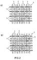
- FIG. 2a shows a fabric made of carbon fibers 1 with glass fibers 2.
- the carbon fibers 1 are each arranged adjacent to a glass fiber 2 and vice versa, the fibers are arranged parallel and at a distance from each other.
- Fig. 2b shows a fabric like Fig. 2a only the fabric is additionally pretreated here, so that the crossing points 5 are fixed. A fixed crossing point 5 is highlighted as an example in FIG. 2b.
- This fabric is coated with hardened UP or vinyl ester resin. The dimensional stability is hereby achieved.
- FIG. 3a shows a fabric 4 with carbon fibers 1.
- the fabric here is as in FIG. 2b pre-treated.
- 3b shows this fabric deformed and hardened. This is shown in FIG. 3c
- the carbon fibers 1 in these Molded parts can then be used as antennas.
- FIG. 4a, b show pressed-in receiving antennas in the primary molded part 3a (FIG. 4a) and in the secondary molding 3b (Fig. 4b).
- the antenna is identified by reference number 7.
- 5a, b show a similar arrangement, but for transmit antennas.
- additional another metal-coated (preferably aluminum-coated) fabric 8 for Shielding provided.
- the figures only show the arrangement of Antennas 7 in one form 3.
Landscapes
- Engineering & Computer Science (AREA)
- Remote Sensing (AREA)
- Reinforced Plastic Materials (AREA)
- Details Of Aerials (AREA)
- Woven Fabrics (AREA)
- Moulding By Coating Moulds (AREA)
Abstract
Description
- Fig. 1
- ein Kohlefaserlaminat,
- Fig. 2a
- eine Draufsicht auf ein Gewebe mit Kohlefaserrovings,
- Fig. 2b
- eine Draufsicht auf ein vorbehandeltes Gewebe mit Kohlefaserrovings,
- Fig. 3a
- ein Gewebe mit Kohlefaserrovings ähnlich Fig. 2b,
- Fig. 3b
- das Gewebe von Fig. 3a verformt und gehärtet und
- Fig. 3c
- das Gewebe von Fig. 3b mit SMC verpreßt,
- Fig. 4
- eingepreßte Empfangsantennen im Primärformteil (Fig. 4a) und im Sekundärformteil (Fig. 4b), und
- Fig. 5
- eingepreßte Sendeantennen im Primärformteil (Fig. 5a) und im Sekundärformteil (Fig. 5b).
Claims (11)
- Faserverstärktes Kunststoff-Formteil, dadurch gekennzeichnet, daß in das Formteil (3) mindestens eine Antenne (7) integriert ist.
- Formteil nach Anspruch 1, dadurch gekennzeichnet, daß Fasern des Formteils (3) eine elektrische Leitfähigkeit besitzen und diese Fasern die Antenne bilden.
- Formteil nach Anspruch 2, dadurch gekennzeichnet, daß die Fasern Kohlefasern (1) oder Metallfasern (Drähte) bevorzugt Kupferfasern (Drähte) sind.
- Formteil nach einem der Ansprüche 2 oder 3, dadurch gekennzeichnet, daß das Formteil (3) aus bis zu 60 Gewichtsprozent Kohlefasern (1) besteht.
- Formteil nach einem der Ansprüche 2 bis 4, dadurch gekennzeichnet, daß ein Gewebe (4) in das Formteil (3) eingepreßt wird, welches in Kette- oder Schußrichtung Kohlefasern (1) oder Metallfasern (Drähte) bevorzugt Kupferfasern (Drähte) aufweist.
- Formteil nach Anspruch 5, dadurch gekennzeichnet, daß die Kohlefasern (1) oder Metallfasern (Drähte) im Gewebe (4) mit Abstand voneinander angeordnet sind.
- Formteil nach einem der Ansprüche 2 bis 6, dadurch gekennzeichnet, daß die Dicke und/oder Länge der Fasern (1) je nach der erforderlichen Antennenabstimmung ausgesucht ist.
- Formteil nach einem der Ansprüche 2 bis 7, dadurch gekennzeichnet, daß die Fasern (1) bzw. das Gewebe (4) mit ausgehärtetem UP- oder Vinylesterharz beschichtet sind.
- Formteil nach einem der Ansprüche 1 bis 8, dadurch gekennzeichnet, daß das Formteil (3) mit der integrierten Antenne bzw. den Antennen an einem Fahrzeug angeordnet ist und z. B. ein Kofferraumdeckel ist oder im oder am Stoßfänger angeordnet ist.
- Formteil nach einem der Ansprüche 1 bis 9, dadurch gekennzeichnet, daß bei Sendeantennen eine zusätzliche Metallabschirmung (8) in das Formteil (3) integriert ist.
- Formte nach Anspruch 10, dadurch gekennzeichnet, daß die Metallabschirmung (8) ein mit Aluminium bedampftes synthetisches Fasergewebe oder Vlies ist.
Applications Claiming Priority (4)
| Application Number | Priority Date | Filing Date | Title |
|---|---|---|---|
| DE19701147 | 1997-01-15 | ||
| DE19701147 | 1997-01-15 | ||
| DE1997129972 DE19729972A1 (de) | 1997-07-12 | 1997-07-12 | Faserverstärktes Kunststoff-Formteil mit integrierter Antenne |
| DE19729972 | 1997-07-12 |
Publications (3)
| Publication Number | Publication Date |
|---|---|
| EP0854536A2 true EP0854536A2 (de) | 1998-07-22 |
| EP0854536A3 EP0854536A3 (de) | 2000-07-05 |
| EP0854536B1 EP0854536B1 (de) | 2007-05-09 |
Family
ID=26033111
Family Applications (1)
| Application Number | Title | Priority Date | Filing Date |
|---|---|---|---|
| EP98100191A Expired - Lifetime EP0854536B1 (de) | 1997-01-15 | 1998-01-08 | Faserverstärktes Kunststoff-Formteil mit integrierter Antenne |
Country Status (3)
| Country | Link |
|---|---|
| EP (1) | EP0854536B1 (de) |
| AT (1) | ATE362202T1 (de) |
| DE (1) | DE59813996D1 (de) |
Cited By (17)
| Publication number | Priority date | Publication date | Assignee | Title |
|---|---|---|---|---|
| EP1221738A3 (de) * | 2000-12-27 | 2002-10-23 | The Furukawa Electric Co., Ltd. | Kleine Antenne und Verfahren zu deren Herstellung |
| EP1241731A3 (de) * | 2001-03-16 | 2003-09-17 | DaimlerChrysler AG | Antennenanordnung |
| WO2004034511A3 (de) * | 2002-09-12 | 2004-06-17 | Daimler Chrysler Ag | Integrierte antennenstrukturen, integrierte elektronische komponentenstrukturen und verfahren zu ihrer herstellung |
| US6950068B2 (en) | 2001-11-15 | 2005-09-27 | Filtronic Lk Oy | Method of manufacturing an internal antenna, and antenna element |
| US6970423B2 (en) | 2001-01-18 | 2005-11-29 | Lucent Technologies Inc. | Universal mobile telecommunications system (UMTS) quality of service (QoS) supporting asymmetric traffic classes |
| FR2884471A1 (fr) * | 2005-04-18 | 2006-10-20 | Plastic Omnium Cie | Piece de renfort pour vehicule automobile et utilisation d'une telle piece comme antenne |
| EP1783859A1 (de) * | 2005-10-20 | 2007-05-09 | EADS Deutschland GmbH | Verfahren zur Herstellung einer strukturintegrierten Antenne |
| WO2008012300A1 (de) * | 2006-07-26 | 2008-01-31 | Universität Bremen | Antenne in einem faserverstärkten verbundwerkstoff und verfahren zur ausbildung einer antenne in einem faserverstärkten verbundwerkstoff |
| WO2008019157A1 (en) * | 2006-08-08 | 2008-02-14 | Sensormatic Electronics Corporation | Thin-film eas and rfid antennas |
| GB2444360A (en) * | 2006-11-30 | 2008-06-04 | Cotech Inc | Antenna embedded in a laminated and moulded shell of a device |
| DE102006056890A1 (de) * | 2006-12-01 | 2008-06-05 | Airbus Deutschland Gmbh | Wandelement mit einer Antenneneinrichtung |
| US8164527B2 (en) | 2011-03-03 | 2012-04-24 | Tangitek, Llc | Antenna apparatus and method for reducing background noise and increasing reception sensitivity |
| US8854275B2 (en) | 2011-03-03 | 2014-10-07 | Tangitek, Llc | Antenna apparatus and method for reducing background noise and increasing reception sensitivity |
| US9055667B2 (en) | 2011-06-29 | 2015-06-09 | Tangitek, Llc | Noise dampening energy efficient tape and gasket material |
| US10262775B2 (en) | 2011-07-11 | 2019-04-16 | Tangitek, Llc | Energy efficient noise dampening cables |
| CN114447581A (zh) * | 2020-11-06 | 2022-05-06 | 大众汽车股份公司 | 天线装置 |
| US11426950B2 (en) | 2015-07-21 | 2022-08-30 | Tangitek, Llc | Electromagnetic energy absorbing three dimensional flocked carbon fiber composite materials |
Family Cites Families (6)
| Publication number | Priority date | Publication date | Assignee | Title |
|---|---|---|---|---|
| US4370658A (en) * | 1981-04-29 | 1983-01-25 | Hill Fred G | Antenna apparatus and method for making same |
| DE3248147A1 (de) * | 1982-12-27 | 1984-06-28 | Siemens AG, 1000 Berlin und 8000 München | Metallisierte formteile aus kunststoff fuer technische gehaeuse zur abschirmung gegenueber elektromagnetischen stoerfeldern |
| JPS6146099A (ja) * | 1984-08-10 | 1986-03-06 | 株式会社ブリヂストン | 電磁波反射体 |
| JPS62216300A (ja) * | 1986-03-17 | 1987-09-22 | 株式会社イナックス | 導電性不織布樹脂複合成形板の製法 |
| DE4008899C1 (en) * | 1990-03-20 | 1991-04-18 | Webasto Ag Fahrzeugtechnik, 8035 Stockdorf, De | Spoiler arrangement for roof of vehicle - comprises frame of glass-fibre reinforced polyester resin, lateral member and angled front spoiler section |
| DE4116232A1 (de) * | 1991-05-17 | 1992-11-19 | Hirschmann Richard Gmbh Co | Antennenanordnung |
-
1998
- 1998-01-08 AT AT98100191T patent/ATE362202T1/de not_active IP Right Cessation
- 1998-01-08 EP EP98100191A patent/EP0854536B1/de not_active Expired - Lifetime
- 1998-01-08 DE DE59813996T patent/DE59813996D1/de not_active Expired - Fee Related
Cited By (23)
| Publication number | Priority date | Publication date | Assignee | Title |
|---|---|---|---|---|
| EP1221738A3 (de) * | 2000-12-27 | 2002-10-23 | The Furukawa Electric Co., Ltd. | Kleine Antenne und Verfahren zu deren Herstellung |
| US6639557B2 (en) | 2000-12-27 | 2003-10-28 | The Furukawa Electric Co., Ltd. | Small antenna and manufacturing method thereof |
| US6970423B2 (en) | 2001-01-18 | 2005-11-29 | Lucent Technologies Inc. | Universal mobile telecommunications system (UMTS) quality of service (QoS) supporting asymmetric traffic classes |
| EP1241731A3 (de) * | 2001-03-16 | 2003-09-17 | DaimlerChrysler AG | Antennenanordnung |
| US6950068B2 (en) | 2001-11-15 | 2005-09-27 | Filtronic Lk Oy | Method of manufacturing an internal antenna, and antenna element |
| WO2004034511A3 (de) * | 2002-09-12 | 2004-06-17 | Daimler Chrysler Ag | Integrierte antennenstrukturen, integrierte elektronische komponentenstrukturen und verfahren zu ihrer herstellung |
| FR2884471A1 (fr) * | 2005-04-18 | 2006-10-20 | Plastic Omnium Cie | Piece de renfort pour vehicule automobile et utilisation d'une telle piece comme antenne |
| EP1714835A1 (de) | 2005-04-18 | 2006-10-25 | Compagnie Plastic Omnium | Verstärkungsteil für ein Kraftfahrzeug und Verwendung desselben als Antenne |
| EP1783859A1 (de) * | 2005-10-20 | 2007-05-09 | EADS Deutschland GmbH | Verfahren zur Herstellung einer strukturintegrierten Antenne |
| WO2008012300A1 (de) * | 2006-07-26 | 2008-01-31 | Universität Bremen | Antenne in einem faserverstärkten verbundwerkstoff und verfahren zur ausbildung einer antenne in einem faserverstärkten verbundwerkstoff |
| WO2008019157A1 (en) * | 2006-08-08 | 2008-02-14 | Sensormatic Electronics Corporation | Thin-film eas and rfid antennas |
| US7973729B2 (en) | 2006-08-08 | 2011-07-05 | Sensormatic Electronics, LLC | Thin-film EAS and RFID antennas |
| GB2444360A (en) * | 2006-11-30 | 2008-06-04 | Cotech Inc | Antenna embedded in a laminated and moulded shell of a device |
| DE102006056890A1 (de) * | 2006-12-01 | 2008-06-05 | Airbus Deutschland Gmbh | Wandelement mit einer Antenneneinrichtung |
| US7701403B2 (en) | 2006-12-01 | 2010-04-20 | Airbus Deutschland Gmbh | Wall element with an antenna device |
| DE102006056890B4 (de) * | 2006-12-01 | 2011-08-25 | Airbus Operations GmbH, 21129 | Wandelement mit einer Antenneneinrichtung |
| US8164527B2 (en) | 2011-03-03 | 2012-04-24 | Tangitek, Llc | Antenna apparatus and method for reducing background noise and increasing reception sensitivity |
| US8854275B2 (en) | 2011-03-03 | 2014-10-07 | Tangitek, Llc | Antenna apparatus and method for reducing background noise and increasing reception sensitivity |
| US9782948B2 (en) | 2011-03-03 | 2017-10-10 | Tangitek, Llc | Antenna apparatus and method for reducing background noise and increasing reception sensitivity |
| US9055667B2 (en) | 2011-06-29 | 2015-06-09 | Tangitek, Llc | Noise dampening energy efficient tape and gasket material |
| US10262775B2 (en) | 2011-07-11 | 2019-04-16 | Tangitek, Llc | Energy efficient noise dampening cables |
| US11426950B2 (en) | 2015-07-21 | 2022-08-30 | Tangitek, Llc | Electromagnetic energy absorbing three dimensional flocked carbon fiber composite materials |
| CN114447581A (zh) * | 2020-11-06 | 2022-05-06 | 大众汽车股份公司 | 天线装置 |
Also Published As
| Publication number | Publication date |
|---|---|
| ATE362202T1 (de) | 2007-06-15 |
| EP0854536A3 (de) | 2000-07-05 |
| EP0854536B1 (de) | 2007-05-09 |
| DE59813996D1 (de) | 2007-06-21 |
Similar Documents
| Publication | Publication Date | Title |
|---|---|---|
| EP0854536A2 (de) | Faserverstärktes Kunststoff-Formteil mit integrierter Antenne | |
| EP0974478B1 (de) | Türmodul für Kraftfahrzeuge mit Funktionselementen aus Kunststoff | |
| DE102013222435B4 (de) | Magnetkernelement, Magnetkernmodul und ein das Magnetkernmodul verwendendes induktives Bauelement | |
| DE102013112413A1 (de) | Batteriegehäuseteil und Batteriegehäuse für eine Traktionsbatterie eines Elektrofahrzeugs | |
| DE19931189A1 (de) | Verfahren zur Herstellung von Bauteilen mit darin angeordneten elektrischen Leiterbahnen sowie danach hergestellte Bauteile, insbesondere als Türmodule für Kraftfahrzeuge | |
| EP0946355B1 (de) | Mehrlagiger verbundkörper | |
| DE102020118348B4 (de) | Formteil für ein mobiles Endgerät mit Sende und/oder Empfangsvorrichtung aus kohlenstofffaserverstärktem Kunststoff | |
| DE19963332A1 (de) | Drahtleitungsträger und Verfahren zum Fertigen eines Drahtleitungsträgers | |
| DE19729972A1 (de) | Faserverstärktes Kunststoff-Formteil mit integrierter Antenne | |
| EP0955191B1 (de) | Einstückiger Türmodul für Kraftfahrzeuge | |
| WO1997012263A2 (de) | Transponder und verfahren zur herstellung eines transponders | |
| DE19712098A1 (de) | Gehäuse für einen Radarsensor | |
| DE10259981A1 (de) | Karosseriebauteil | |
| DE102022000284A1 (de) | Schienensystem für ein schienengebundenes Fahrzeug | |
| EP1467431B1 (de) | Kontaktadapter für die Kontaktierung einer Antennenstruktur eines Fahrzeuges | |
| EP1238841A2 (de) | Deckel für ein Schiebedach | |
| EP1698019B1 (de) | Fahrzeugscheibenantenne | |
| DE19729403B4 (de) | Antennenvorrichtung für ein Diebstahlschutzsystem eines Kraftfahrzeugs | |
| DE102021004993A1 (de) | System zur Übertragung von elektrischer Energie | |
| DE102020134562A1 (de) | Gehäuse zur Aufnahme eines elektrischen Energiespeichers für ein Fahrzeug | |
| DE102020008085B4 (de) | Formteil für ein mobiles Endgerät mit Sende und/oder Empfangsvorrichtung aus kohlenstofffaserverstärktem Kunststoff | |
| DE69923001T2 (de) | Reflektor elektromagnetischer Wellen und Verfahren zu seiner Herstellung | |
| DE102013219377A1 (de) | Antennenanordnung mit antenneneinheit und verbindereinheit | |
| DE102010043430A1 (de) | Zweikomponentiges Lagerschild für eine Elektromaschine sowie Herstellungsverfahren für selbiges | |
| EP1091375B1 (de) | Mehrfachschalter |
Legal Events
| Date | Code | Title | Description |
|---|---|---|---|
| PUAI | Public reference made under article 153(3) epc to a published international application that has entered the european phase |
Free format text: ORIGINAL CODE: 0009012 |
|
| AK | Designated contracting states |
Kind code of ref document: A2 Designated state(s): AT BE CH DE DK ES FI FR GB GR IT LI NL PT SE |
|
| AX | Request for extension of the european patent |
Free format text: AL;LT;LV;MK;RO;SI |
|
| PUAL | Search report despatched |
Free format text: ORIGINAL CODE: 0009013 |
|
| AK | Designated contracting states |
Kind code of ref document: A3 Designated state(s): AT BE CH DE DK ES FI FR GB GR IE IT LI LU MC NL PT SE |
|
| AX | Request for extension of the european patent |
Free format text: AL;LT;LV;MK;RO;SI |
|
| 17P | Request for examination filed |
Effective date: 20010105 |
|
| AKX | Designation fees paid |
Free format text: AT BE CH DE DK ES FI FR GB GR IT LI NL PT SE |
|
| 17Q | First examination report despatched |
Effective date: 20050405 |
|
| GRAP | Despatch of communication of intention to grant a patent |
Free format text: ORIGINAL CODE: EPIDOSNIGR1 |
|
| GRAS | Grant fee paid |
Free format text: ORIGINAL CODE: EPIDOSNIGR3 |
|
| GRAA | (expected) grant |
Free format text: ORIGINAL CODE: 0009210 |
|
| AK | Designated contracting states |
Kind code of ref document: B1 Designated state(s): AT BE CH DE DK ES FI FR GB GR IT LI NL PT SE |
|
| PG25 | Lapsed in a contracting state [announced via postgrant information from national office to epo] |
Ref country code: FI Free format text: LAPSE BECAUSE OF FAILURE TO SUBMIT A TRANSLATION OF THE DESCRIPTION OR TO PAY THE FEE WITHIN THE PRESCRIBED TIME-LIMIT Effective date: 20070509 |
|
| REG | Reference to a national code |
Ref country code: GB Ref legal event code: FG4D Free format text: NOT ENGLISH |
|
| REG | Reference to a national code |
Ref country code: CH Ref legal event code: EP |
|
| REF | Corresponds to: |
Ref document number: 59813996 Country of ref document: DE Date of ref document: 20070621 Kind code of ref document: P |
|
| PG25 | Lapsed in a contracting state [announced via postgrant information from national office to epo] |
Ref country code: SE Free format text: LAPSE BECAUSE OF FAILURE TO SUBMIT A TRANSLATION OF THE DESCRIPTION OR TO PAY THE FEE WITHIN THE PRESCRIBED TIME-LIMIT Effective date: 20070809 |
|
| PG25 | Lapsed in a contracting state [announced via postgrant information from national office to epo] |
Ref country code: ES Free format text: LAPSE BECAUSE OF FAILURE TO SUBMIT A TRANSLATION OF THE DESCRIPTION OR TO PAY THE FEE WITHIN THE PRESCRIBED TIME-LIMIT Effective date: 20070820 |
|
| NLV1 | Nl: lapsed or annulled due to failure to fulfill the requirements of art. 29p and 29m of the patents act | ||
| GBV | Gb: ep patent (uk) treated as always having been void in accordance with gb section 77(7)/1977 [no translation filed] |
Effective date: 20070509 |
|
| EN | Fr: translation not filed | ||
| PG25 | Lapsed in a contracting state [announced via postgrant information from national office to epo] |
Ref country code: PT Free format text: LAPSE BECAUSE OF FAILURE TO SUBMIT A TRANSLATION OF THE DESCRIPTION OR TO PAY THE FEE WITHIN THE PRESCRIBED TIME-LIMIT Effective date: 20071009 Ref country code: NL Free format text: LAPSE BECAUSE OF FAILURE TO SUBMIT A TRANSLATION OF THE DESCRIPTION OR TO PAY THE FEE WITHIN THE PRESCRIBED TIME-LIMIT Effective date: 20070509 Ref country code: DK Free format text: LAPSE BECAUSE OF FAILURE TO SUBMIT A TRANSLATION OF THE DESCRIPTION OR TO PAY THE FEE WITHIN THE PRESCRIBED TIME-LIMIT Effective date: 20070509 |
|
| PLBE | No opposition filed within time limit |
Free format text: ORIGINAL CODE: 0009261 |
|
| STAA | Information on the status of an ep patent application or granted ep patent |
Free format text: STATUS: NO OPPOSITION FILED WITHIN TIME LIMIT |
|
| 26N | No opposition filed |
Effective date: 20080212 |
|
| PG25 | Lapsed in a contracting state [announced via postgrant information from national office to epo] |
Ref country code: IT Free format text: LAPSE BECAUSE OF FAILURE TO SUBMIT A TRANSLATION OF THE DESCRIPTION OR TO PAY THE FEE WITHIN THE PRESCRIBED TIME-LIMIT Effective date: 20070509 Ref country code: GR Free format text: LAPSE BECAUSE OF FAILURE TO SUBMIT A TRANSLATION OF THE DESCRIPTION OR TO PAY THE FEE WITHIN THE PRESCRIBED TIME-LIMIT Effective date: 20070810 Ref country code: GB Free format text: LAPSE BECAUSE OF FAILURE TO SUBMIT A TRANSLATION OF THE DESCRIPTION OR TO PAY THE FEE WITHIN THE PRESCRIBED TIME-LIMIT Effective date: 20070509 |
|
| BERE | Be: lapsed |
Owner name: MENZOLIT-FIBRON G.M.B.H. Effective date: 20080131 |
|
| PG25 | Lapsed in a contracting state [announced via postgrant information from national office to epo] |
Ref country code: FR Free format text: LAPSE BECAUSE OF FAILURE TO SUBMIT A TRANSLATION OF THE DESCRIPTION OR TO PAY THE FEE WITHIN THE PRESCRIBED TIME-LIMIT Effective date: 20080104 |
|
| REG | Reference to a national code |
Ref country code: CH Ref legal event code: PL |
|
| PG25 | Lapsed in a contracting state [announced via postgrant information from national office to epo] |
Ref country code: LI Free format text: LAPSE BECAUSE OF NON-PAYMENT OF DUE FEES Effective date: 20080131 Ref country code: DE Free format text: LAPSE BECAUSE OF NON-PAYMENT OF DUE FEES Effective date: 20080801 Ref country code: CH Free format text: LAPSE BECAUSE OF NON-PAYMENT OF DUE FEES Effective date: 20080131 |
|
| PG25 | Lapsed in a contracting state [announced via postgrant information from national office to epo] |
Ref country code: BE Free format text: LAPSE BECAUSE OF NON-PAYMENT OF DUE FEES Effective date: 20080131 |
|
| PG25 | Lapsed in a contracting state [announced via postgrant information from national office to epo] |
Ref country code: AT Free format text: LAPSE BECAUSE OF NON-PAYMENT OF DUE FEES Effective date: 20080108 |