EP0854253A1 - Aérateur universel extrudé à éléments plissés - Google Patents
Aérateur universel extrudé à éléments plissés Download PDFInfo
- Publication number
- EP0854253A1 EP0854253A1 EP97100719A EP97100719A EP0854253A1 EP 0854253 A1 EP0854253 A1 EP 0854253A1 EP 97100719 A EP97100719 A EP 97100719A EP 97100719 A EP97100719 A EP 97100719A EP 0854253 A1 EP0854253 A1 EP 0854253A1
- Authority
- EP
- European Patent Office
- Prior art keywords
- ventilation element
- side part
- element according
- material thickness
- ventilation
- Prior art date
- Legal status (The legal status is an assumption and is not a legal conclusion. Google has not performed a legal analysis and makes no representation as to the accuracy of the status listed.)
- Withdrawn
Links
- 239000000463 material Substances 0.000 claims abstract description 47
- 238000009423 ventilation Methods 0.000 claims description 57
- 239000000853 adhesive Substances 0.000 claims description 21
- 230000001070 adhesive effect Effects 0.000 claims description 21
- 238000001125 extrusion Methods 0.000 claims description 9
- 238000004519 manufacturing process Methods 0.000 claims description 9
- 238000000034 method Methods 0.000 claims description 9
- XLYOFNOQVPJJNP-UHFFFAOYSA-N water Substances O XLYOFNOQVPJJNP-UHFFFAOYSA-N 0.000 claims description 7
- 238000004026 adhesive bonding Methods 0.000 claims description 4
- 239000011324 bead Substances 0.000 claims description 3
- 238000005452 bending Methods 0.000 claims description 3
- 239000000654 additive Substances 0.000 claims description 2
- 239000012790 adhesive layer Substances 0.000 claims description 2
- 239000002390 adhesive tape Substances 0.000 claims description 2
- 230000008569 process Effects 0.000 claims description 2
- 238000003466 welding Methods 0.000 claims description 2
- 229920002457 flexible plastic Polymers 0.000 claims 1
- 238000000465 moulding Methods 0.000 claims 1
- 229920003023 plastic Polymers 0.000 abstract description 3
- 239000004033 plastic Substances 0.000 abstract description 3
- 238000007789 sealing Methods 0.000 description 6
- 230000009471 action Effects 0.000 description 3
- 230000008901 benefit Effects 0.000 description 3
- 230000000694 effects Effects 0.000 description 3
- 239000003292 glue Substances 0.000 description 3
- 230000007704 transition Effects 0.000 description 3
- 239000000428 dust Substances 0.000 description 2
- 230000006978 adaptation Effects 0.000 description 1
- XAGFODPZIPBFFR-UHFFFAOYSA-N aluminium Chemical compound [Al] XAGFODPZIPBFFR-UHFFFAOYSA-N 0.000 description 1
- 229910052782 aluminium Inorganic materials 0.000 description 1
- 238000009826 distribution Methods 0.000 description 1
- 239000013013 elastic material Substances 0.000 description 1
- 239000004745 nonwoven fabric Substances 0.000 description 1
- 239000011148 porous material Substances 0.000 description 1
- 230000000284 resting effect Effects 0.000 description 1
- 238000005096 rolling process Methods 0.000 description 1
- 238000009958 sewing Methods 0.000 description 1
- 125000006850 spacer group Chemical group 0.000 description 1
- 238000003892 spreading Methods 0.000 description 1
- 230000007480 spreading Effects 0.000 description 1
- 238000003860 storage Methods 0.000 description 1
- 238000009827 uniform distribution Methods 0.000 description 1
Images


Classifications
-
- E—FIXED CONSTRUCTIONS
- E04—BUILDING
- E04D—ROOF COVERINGS; SKY-LIGHTS; GUTTERS; ROOF-WORKING TOOLS
- E04D1/00—Roof covering by making use of tiles, slates, shingles, or other small roofing elements
- E04D1/36—Devices for sealing the spaces or joints between roof-covering elements
-
- E—FIXED CONSTRUCTIONS
- E04—BUILDING
- E04D—ROOF COVERINGS; SKY-LIGHTS; GUTTERS; ROOF-WORKING TOOLS
- E04D13/00—Special arrangements or devices in connection with roof coverings; Protection against birds; Roof drainage ; Sky-lights
- E04D13/17—Ventilation of roof coverings not otherwise provided for
- E04D13/174—Ventilation of roof coverings not otherwise provided for on the ridge of the roof
- E04D13/176—Ventilation of roof coverings not otherwise provided for on the ridge of the roof formed by flexible material suitable to be rolled up
Definitions
- the invention relates to a ventilation element to cover the length of the roof running gap between a ridge or ridge plank and roofing slabs according to the preamble of claim 1 and a method for manufacturing of such a ventilation element.
- Such ventilation elements are known as rollable goods or as rigid fans. They are attached to their middle part on a ridge or ridge slat and seal the gap between this slat and the roofing slabs of a roof, whereby they lie with their outer edge areas on the covering plates come.
- a rollable ventilation element is known from DE 40 01 766.
- This fan is made of a nonwoven and pleated in the area of its outer edges, so Can be enlarged in area to cover the valleys of the roofing slabs to be able to nestle.
- the necessary air exchange between the areas below and above the fan is realized in that air permeable Nonwoven material is used. Because the nonwoven material is impermeable to water but must be permeable to air, this fan has only very small, in the nonwoven fabric introduced air passage pores, which dust over time and become impermeable to air, which means that the ventilation function is no longer fulfilled can.
- ridge and degree ventilation element is known from EP-0 117 391. It consists of a rigid middle section with adjoining side sections that are made of comb-like elastic teeth are built, on which a nonwoven material in pleated shape is attached. The side parts nestle here again the roofing slabs, whereby the sealing is achieved. In the stiff The middle part of this fan is next to the support area for the ridge or ridge slat Ventilation openings are provided through which the air from the roof structure after can pull off at the top. Unfortunately, this rigid ventilation element is not can be rolled up, which increases storage and distribution costs.
- this elastic element is intentionally made of a rigid material, thus the spring effect created during assembly the toothed side parts can press into the troughs of the roofing panels, so that a Shape adaptation and sealing is created.
- the manufacture of such elements is elaborate and their uses are on certain roof tile shapes limited.
- a ventilation element is known from German Patent No. 44 41 296, which can be rolled up and at the transition between the middle section and side section both parts are made with a relatively large material thickness.
- the material thickness of the Side parts decrease towards their edge area in order to adapt well to the To ensure the shape of the roofing tiles, while in the transition area between the middle part and side part relatively large material thickness an elastic Can exert spring action, the side parts in the recesses of the roofing panels pushes in.
- the object of the present invention is to overcome the disadvantages mentioned above To overcome the state of the art.
- a ventilation element be created, the side parts of which can be spread out and thus the roofing panels are adaptable, but essentially no restoring forces develop so that the side panels on their edges after laying without there are leaks on the roof covering panels.
- This object is achieved by designing a ventilation element according to the characterizing part of claim 1 solved.
- the middle part which is made of the relatively stronger material, ensures sufficient stability of the ventilation element.
- the material thickness is the middle part in the range of 0.6 mm to 1.2 mm, in particular 0.8 mm to 1 mm and preferably 0.9 mm, while the material thickness of each side part accordingly in the range from 0.2 mm to 0.8 mm, in particular 0.4 mm to 0.7 mm and is preferably 0.5.
- the pleating of each side part is essentially designed wavy.
- a zigzag course have, while for a medium stretchability (medium-vaulted roof covering panels) a zigzag course with flattened tips on one side and for great stretchability (strongly arched roof covering panels) a zigzag path with two-sided flattened tips.
- the ventilation element preferably consists of a, in particular modified, PVC material, which is weatherproof, especially resistant, through additives against UV light, is made, and it can be rolled up and laid as yard goods educated.
- the weather resistance brings the outside in particular exposed side parts advantages in terms of service life. Here is particular the resistance to UV light due to the thin material thickness of the Side parts of importance.
- the central strip of the ventilation element has according to the invention spaced apart ventilation openings that in particular as protrusions protruding in the median strip towards the top are formed, the outer edges of which form water protection edges and their material is thickened compared to the surrounding areas.
- the ventilation element according to the invention can also be carried out so that in the section where the median strip adjoins the side part, in the longitudinal direction of the Ventilation element a bending zone with one opposite the adjacent areas reduced material thickness runs.
- the side parts of the Ventilation element after resting the median strip on the ridge or Burr slat fall down by its own weight and into the valleys of the roofing sheets.
- Adhesives in particular, are suitably attached to the underside of the side part Adhesive beads or tape arranged so that the pleating of the Partly, advantageously, an adhesive layer into the pleating valleys having.
- the adhesives are used to sink into the valleys of the roof tiles Fix sealing strips there in order to obtain an optimal sealing effect.
- the A flat strip is molded into the underside of the side part at the edge.
- Such a flat strip consists of an elastic material that is also easy in the Let roofing sheets molded in. It ensures even better customization to the roof tile shape and the adhesive can with a uniform distribution be applied to the flattened underside of the side part.
- the before described embodiments of the ventilation elements according to the invention can be integral with the middle part and the side parts by means of an extrusion technique getting produced.
- each side part forms a separate component, which with the middle part in particular by welding, gluing, riveting, folding, inserting or extrusion molding or forms is connected.
- each side part together with the Middle part is extruded, the extrusion being the material thickness of each side part approximately from the edge adjoining the middle part to the outer edge is kept the same and much less than the material thickness of the middle part, can be made a ventilation element that the previously described Has advantages.
- the ventilation element can be made in one piece with those previously discussed Refinements or with separate side parts that are made during the Extrusion process can be connected to the middle part. In the latter case on the one hand the possibility of the side part initially in flat form with the middle part to connect and then pleat, while on the other hand the side part is already in pleated form are extruded into the material of the middle part can.
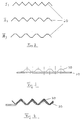
- the ventilation element shown in Figure 1 consists essentially of a Middle part 10, on the upper and lower edge of the pleated side parts 20th are arranged. According to the invention, but not visible in the drawing, that is Middle part 10 executed much stronger than that in terms of material thickness Side parts 20. If, for example, the middle part 10 has a material thickness of 0.8 mm to 0.9 mm, the side parts 20 would be about 0.4 mm thick. By this small material thickness can be the side parts 20 when molded into the bulges the roofing tiles are easily stretched; they nestle up of fitting completely to the surface of these panels because of the pleating no restoring forces have been developed to restore the original waveform could. The side parts 20 also fall, since they are the slightest over their entire width Material thickness are relatively light in the troughs of the roofing slabs into it and the extension i.e. the stretching of the pleating for adjustment makes no difficulties.
- the ventilation element comes on a ridge or Ridge to lie and is attached there.
- the Ventilation element according to Figure 1 mutually arranged longitudinally spaced ventilation openings 9 on. These are as protrusions 11 projecting towards the top trained with a hole.
- Beading 12 is attached around the edge area. The material is in this area still somewhat thickened, which provides good stability of the deposits 11 becomes. In particular, this stability can prevent that when rolling up of the fan, the deposits 11 are pressed.
- FIG. 2 now shows three different pleating forms for side parts 20, which are used depending on the curvature of the roofing slabs.
- a zigzag wavy pleating comes especially used when the roof covering panels are hardly arched are.
- the pleating With higher roofing slabs, i.e. in a medium altitude range, the pleating must be stretched more.
- a pleating form is suitable for this, whose zigzag course is flattened at the top, as shown at II) in Figure 2 is.
- the pleating must have a large stretchability be provided. This is achieved, for example, in the cross section, which is shown in Figure 2 at III) and flattened on both sides in the zigzag shape is.
- the stretchability of the pleating can also be determined using the pleating shape to adjust.
- the side panels with all three shown Pleating forms because of their small material thickness according to the invention Have the advantage of conforming completely to the roof covering and remain there after application, without due to the resulting restoring forces causing leaks in the pleating.
- FIGS. 3 and 4 show two different possibilities for an adhesive 30 to attach the underside of a side part 20 in the edge region thereof.
- the pleating has a zigzag shape with the top and flattened tips at the bottom.
- An adhesive for example a flexible one double-sided adhesive tape 30, is pleated at the bottom of the lower flats of the side part.
- the pleating stretches along with the flexible adhesive strip 30.
- the side part 20 is then in the area of the adhesive strip 30 pressed onto the roof tiles from above. This essentially becomes the entire lower surface of the side part 20 in contact with the adhesive 30 come that sticks to the roofing sheets themselves.
- the shape of the pleating in FIG. 2 is therefore for use with large extensions deep roof tiles provided.
- the roof tile increases can be up to 80% amount, the restoring forces caused by the stretching of the pleating become quite high with conventional fans with strong material in the side panel can. Such occur in the present ventilation element according to the invention As previously described, the restoring forces do not increase, the adhesion remains tight.
- an adhesive 30 tracks the shape of the pleating, ie in a zigzag shape applied to the side part 20 in the edge area.
- the adhesive 30 again a double-sided adhesive flexible strip can be used, but it can a bead of adhesive material can also be applied.
- the pleating shape in Figure 4 is used with flat roofing slabs. Has an advantageous effect here that if there is only a slight stretching of the pleating, the glue the tips that are still standing up, making them a good one Sealing can be provided.
- FIG. 5 shows continuously with the representations A) to D) the production of a Ventilation element according to the invention, which has a separate side part 20 that is attached to the middle part 10.
- Representation A shows what was initially present in the manufacturing process flat side part 20.
- a flat strip which can consist of a thin aluminum sheet, for example attached lower edge, while on the underside of the strip 21 an adhesive strip 30 is arranged.
- the representation B) shows another starting situation in which the strip 21 is attached to the edge of the side part 20 by a hem. At the again superimposed point of the side part 20 can the attachment for example by sewing or gluing. Below the one with the stripe 21 provided edge, in turn, an adhesive strip 30 is applied.
- the illustration C) now shows a later state of the side part 20 in the manufacturing process, in which the side panel 20 has already been pleated.
- the pleating detects the side part 20 and the strip 21, while the adhesive 30th is uniformly distributed on the underside at the edge of the side part 20.
- one half of the middle part 10 can be seen, that in another Method step is brought together with the side part 20, whereby a finished ventilation element is created, as shown in the illustration D).
- connection is preferably thermal; the two parts 20 and 10 are extruded together, with the pleating naturally also under Exposure to heat is carried out.
- the side part 20 is only because of the better representability has been heavily drawn, as the middle part 10. According to the invention, the side part 20, however, has a significantly smaller material thickness than the central part 10.
Landscapes
- Engineering & Computer Science (AREA)
- Architecture (AREA)
- Civil Engineering (AREA)
- Structural Engineering (AREA)
- Building Environments (AREA)
- Cooling, Air Intake And Gas Exhaust, And Fuel Tank Arrangements In Propulsion Units (AREA)
Priority Applications (2)
| Application Number | Priority Date | Filing Date | Title |
|---|---|---|---|
| EP97100719A EP0854253A1 (fr) | 1997-01-17 | 1997-01-17 | Aérateur universel extrudé à éléments plissés |
| DE29723495U DE29723495U1 (de) | 1997-01-17 | 1997-01-17 | Extrudierter Universallüfter mit plissierten Seitenteilen |
Applications Claiming Priority (1)
| Application Number | Priority Date | Filing Date | Title |
|---|---|---|---|
| EP97100719A EP0854253A1 (fr) | 1997-01-17 | 1997-01-17 | Aérateur universel extrudé à éléments plissés |
Publications (1)
| Publication Number | Publication Date |
|---|---|
| EP0854253A1 true EP0854253A1 (fr) | 1998-07-22 |
Family
ID=8226378
Family Applications (1)
| Application Number | Title | Priority Date | Filing Date |
|---|---|---|---|
| EP97100719A Withdrawn EP0854253A1 (fr) | 1997-01-17 | 1997-01-17 | Aérateur universel extrudé à éléments plissés |
Country Status (2)
| Country | Link |
|---|---|
| EP (1) | EP0854253A1 (fr) |
| DE (1) | DE29723495U1 (fr) |
Cited By (2)
| Publication number | Priority date | Publication date | Assignee | Title |
|---|---|---|---|---|
| WO2002027115A1 (fr) | 2000-09-29 | 2002-04-04 | Andrew Leo Haynes | Solins de garnitures de tuile |
| EP1375775A1 (fr) * | 2002-06-21 | 2004-01-02 | Bernd Meinecke | Elément de ventilation de faíte ou d'arête de toit sous forme de bande |
Citations (11)
| Publication number | Priority date | Publication date | Assignee | Title |
|---|---|---|---|---|
| NL7711857A (nl) * | 1976-10-29 | 1978-05-03 | Braas & Co Gmbh | Nok- of hoekafdichting. |
| EP0117391A2 (fr) | 1983-02-26 | 1984-09-05 | BRAAS & CO. GMBH | Recouvrement de faîte ou d'arête pour toits recouverts de plaques |
| DE8713110U1 (de) * | 1987-09-30 | 1988-01-21 | Fleck, Oskar, 4354 Datteln | Gewölbtes Firstabdichtungs- und -belüftungselement |
| DE4001766A1 (de) | 1990-01-23 | 1991-08-01 | Albrecht Dipl Ing Kloeckner | First- und gratbelueftung fuer pfannendaecher |
| DE9108658U1 (de) * | 1991-07-13 | 1991-09-26 | Fleck, Oskar, 4354 Datteln | Firstentlüftungselement |
| DE9405203U1 (de) * | 1994-03-26 | 1995-04-27 | Gehring Manfred Dr | Rollbarer Dichtungsstreifen für eine First- oder Gratabdeckung |
| DE29504197U1 (de) * | 1995-03-15 | 1995-05-04 | Norm A.M.C. AG, Erstfeld, Uri | Dichtungsstreifen |
| DE29504548U1 (de) * | 1995-03-17 | 1995-06-22 | Bwk Dachzubehoer Gmbh | Dichtungsstreifen zum Herstellen von First- oder Gratabdeckungen |
| DE4441296C1 (de) | 1994-11-21 | 1996-07-04 | Alfons Knoche | Universallüfter mit plissierten Seitenteilen in gespritzter Ausführung |
| EP0722025A1 (fr) * | 1994-12-14 | 1996-07-17 | Vuille S.A. | Bande de protection pour le faîte d'un toit |
| DE29608830U1 (de) * | 1996-05-17 | 1996-08-14 | Norm Amc Ag | Lüftungselement für Dächer |
-
1997
- 1997-01-17 EP EP97100719A patent/EP0854253A1/fr not_active Withdrawn
- 1997-01-17 DE DE29723495U patent/DE29723495U1/de not_active Expired - Lifetime
Patent Citations (11)
| Publication number | Priority date | Publication date | Assignee | Title |
|---|---|---|---|---|
| NL7711857A (nl) * | 1976-10-29 | 1978-05-03 | Braas & Co Gmbh | Nok- of hoekafdichting. |
| EP0117391A2 (fr) | 1983-02-26 | 1984-09-05 | BRAAS & CO. GMBH | Recouvrement de faîte ou d'arête pour toits recouverts de plaques |
| DE8713110U1 (de) * | 1987-09-30 | 1988-01-21 | Fleck, Oskar, 4354 Datteln | Gewölbtes Firstabdichtungs- und -belüftungselement |
| DE4001766A1 (de) | 1990-01-23 | 1991-08-01 | Albrecht Dipl Ing Kloeckner | First- und gratbelueftung fuer pfannendaecher |
| DE9108658U1 (de) * | 1991-07-13 | 1991-09-26 | Fleck, Oskar, 4354 Datteln | Firstentlüftungselement |
| DE9405203U1 (de) * | 1994-03-26 | 1995-04-27 | Gehring Manfred Dr | Rollbarer Dichtungsstreifen für eine First- oder Gratabdeckung |
| DE4441296C1 (de) | 1994-11-21 | 1996-07-04 | Alfons Knoche | Universallüfter mit plissierten Seitenteilen in gespritzter Ausführung |
| EP0722025A1 (fr) * | 1994-12-14 | 1996-07-17 | Vuille S.A. | Bande de protection pour le faîte d'un toit |
| DE29504197U1 (de) * | 1995-03-15 | 1995-05-04 | Norm A.M.C. AG, Erstfeld, Uri | Dichtungsstreifen |
| DE29504548U1 (de) * | 1995-03-17 | 1995-06-22 | Bwk Dachzubehoer Gmbh | Dichtungsstreifen zum Herstellen von First- oder Gratabdeckungen |
| DE29608830U1 (de) * | 1996-05-17 | 1996-08-14 | Norm Amc Ag | Lüftungselement für Dächer |
Cited By (4)
| Publication number | Priority date | Publication date | Assignee | Title |
|---|---|---|---|---|
| WO2002027115A1 (fr) | 2000-09-29 | 2002-04-04 | Andrew Leo Haynes | Solins de garnitures de tuile |
| EP1330581A1 (fr) * | 2000-09-29 | 2003-07-30 | Andrew Leo Haynes | Solins de garnitures de tuile |
| EP1330581A4 (fr) * | 2000-09-29 | 2005-05-11 | Andrew Leo Haynes | Solins de garnitures de tuile |
| EP1375775A1 (fr) * | 2002-06-21 | 2004-01-02 | Bernd Meinecke | Elément de ventilation de faíte ou d'arête de toit sous forme de bande |
Also Published As
| Publication number | Publication date |
|---|---|
| DE29723495U1 (de) | 1998-09-03 |
Similar Documents
| Publication | Publication Date | Title |
|---|---|---|
| DE8816544U1 (de) | Dichtungsstreifen für eine First- oder Gratabdeckung | |
| EP0791699B1 (fr) | Closoir de ventilation enroulable pour faíte et arête de toits | |
| DE69811189T2 (de) | Filtrationsanordnung | |
| DE4404150C1 (de) | Lüftungsband | |
| EP0911459B1 (fr) | Closoir de ventilation pour faíte ou arête de toit | |
| EP0786568B1 (fr) | Elément d'aération pour toitures | |
| DE19821035B4 (de) | Abdichtungsmatte | |
| EP0854253A1 (fr) | Aérateur universel extrudé à éléments plissés | |
| DE19828721A1 (de) | Dichtungsstreifen | |
| EP0838561B1 (fr) | Elément d'aération pour toitures, avec organe d'étanchéité | |
| DE19733230A1 (de) | Abdichtungsmatte | |
| EP1017912B1 (fr) | Mat d'etancheite | |
| DE4441296C2 (de) | Universallüfter mit plissierten Seitenteilen in gespritzter Ausführung | |
| DE10015094C1 (de) | Lüftungsstreifen für Dächer | |
| EP1002168B1 (fr) | Element de ventilation de faite ou d'aretier | |
| DE9416291U1 (de) | Dichtungsstreifen für First- und/oder Gratabdeckungen | |
| EP1030002B1 (fr) | Elément d'aération de faíte ou d'arête de toit et son procédé de fabrication | |
| DE4244283A1 (de) | First- und/oder Gratabdeckung | |
| EP0707120B1 (fr) | Bande d'étanchéité pour faíte ou arête de couverture et procédé de fabrication | |
| DE20023413U1 (de) | Auf- bzw. abrollbarer Dichtungsstreifen für eine First- oder Gratabdeckung | |
| DE102006001721A1 (de) | Dichtstreifen | |
| DE3844902C2 (de) | Lüfterkappe zur Hinterlüftung von Dächern im First- oder Gratbereich | |
| DE29723782U1 (de) | First- oder Gratbelüftungselement | |
| EP1013845A1 (fr) | Elément de faíte ou d'arête de toit | |
| DE10021937A1 (de) | Auf- bzw. abrollbarer Dichtungsstreifen für eine First- oder Gratabdeckung und Verfahren zu dessen Herstellung |
Legal Events
| Date | Code | Title | Description |
|---|---|---|---|
| PUAI | Public reference made under article 153(3) epc to a published international application that has entered the european phase |
Free format text: ORIGINAL CODE: 0009012 |
|
| AK | Designated contracting states |
Kind code of ref document: A1 Designated state(s): AT BE CH DE ES FR GB IT LI NL SE |
|
| AX | Request for extension of the european patent |
Free format text: AL;LT;LV;RO;SI |
|
| 17P | Request for examination filed |
Effective date: 19980813 |
|
| AKX | Designation fees paid |
Free format text: AT BE CH DE ES FR GB IT LI NL SE |
|
| RBV | Designated contracting states (corrected) |
Designated state(s): AT BE CH DE ES FR GB IT LI NL SE |
|
| 17Q | First examination report despatched |
Effective date: 20020204 |
|
| STAA | Information on the status of an ep patent application or granted ep patent |
Free format text: STATUS: THE APPLICATION IS DEEMED TO BE WITHDRAWN |
|
| 18D | Application deemed to be withdrawn |
Effective date: 20020615 |