EP0853703B2 - Verfahren zur einstellung der anisotropie einer papierbahn - Google Patents
Verfahren zur einstellung der anisotropie einer papierbahn Download PDFInfo
- Publication number
- EP0853703B2 EP0853703B2 EP97926023A EP97926023A EP0853703B2 EP 0853703 B2 EP0853703 B2 EP 0853703B2 EP 97926023 A EP97926023 A EP 97926023A EP 97926023 A EP97926023 A EP 97926023A EP 0853703 B2 EP0853703 B2 EP 0853703B2
- Authority
- EP
- European Patent Office
- Prior art keywords
- forming
- wire
- roll
- web
- twin
- Prior art date
- Legal status (The legal status is an assumption and is not a legal conclusion. Google has not performed a legal analysis and makes no representation as to the accuracy of the status listed.)
- Expired - Lifetime
Links
- 238000000034 method Methods 0.000 title claims abstract description 12
- 239000000725 suspension Substances 0.000 claims abstract description 24
- 230000000694 effects Effects 0.000 claims abstract description 20
- XLYOFNOQVPJJNP-UHFFFAOYSA-N water Substances O XLYOFNOQVPJJNP-UHFFFAOYSA-N 0.000 claims abstract description 11
- 230000015572 biosynthetic process Effects 0.000 claims description 29
- 230000001276 controlling effect Effects 0.000 claims description 3
- 230000001105 regulatory effect Effects 0.000 claims description 3
- 238000007599 discharging Methods 0.000 claims 1
- 239000010410 layer Substances 0.000 description 15
- 239000000835 fiber Substances 0.000 description 11
- 239000004744 fabric Substances 0.000 description 10
- 239000002344 surface layer Substances 0.000 description 5
- 239000002023 wood Substances 0.000 description 5
- 230000007423 decrease Effects 0.000 description 4
- 238000005259 measurement Methods 0.000 description 4
- 230000003247 decreasing effect Effects 0.000 description 3
- 230000001419 dependent effect Effects 0.000 description 3
- 230000014759 maintenance of location Effects 0.000 description 3
- 238000010276 construction Methods 0.000 description 2
- 239000007788 liquid Substances 0.000 description 2
- 238000012423 maintenance Methods 0.000 description 2
- 238000004519 manufacturing process Methods 0.000 description 2
- 230000003749 cleanliness Effects 0.000 description 1
- 230000002301 combined effect Effects 0.000 description 1
- 230000008602 contraction Effects 0.000 description 1
- 239000000945 filler Substances 0.000 description 1
- 230000010349 pulsation Effects 0.000 description 1
- 230000000630 rising effect Effects 0.000 description 1
- 239000007787 solid Substances 0.000 description 1
- 230000002195 synergetic effect Effects 0.000 description 1
Images


Classifications
-
- D—TEXTILES; PAPER
- D21—PAPER-MAKING; PRODUCTION OF CELLULOSE
- D21F—PAPER-MAKING MACHINES; METHODS OF PRODUCING PAPER THEREON
- D21F9/00—Complete machines for making continuous webs of paper
- D21F9/003—Complete machines for making continuous webs of paper of the twin-wire type
-
- D—TEXTILES; PAPER
- D21—PAPER-MAKING; PRODUCTION OF CELLULOSE
- D21F—PAPER-MAKING MACHINES; METHODS OF PRODUCING PAPER THEREON
- D21F1/00—Wet end of machines for making continuous webs of paper
-
- D—TEXTILES; PAPER
- D21—PAPER-MAKING; PRODUCTION OF CELLULOSE
- D21F—PAPER-MAKING MACHINES; METHODS OF PRODUCING PAPER THEREON
- D21F1/00—Wet end of machines for making continuous webs of paper
- D21F1/36—Guiding mechanisms
-
- D—TEXTILES; PAPER
- D21—PAPER-MAKING; PRODUCTION OF CELLULOSE
- D21F—PAPER-MAKING MACHINES; METHODS OF PRODUCING PAPER THEREON
- D21F7/00—Other details of machines for making continuous webs of paper
- D21F7/06—Indicating or regulating the thickness of the layer; Signal devices
Definitions
- Roll and blade forming was originally introduced for newsprint in 1987 as a means for producing formation quality similar to that of a blade former but without the accompanying problems of low retention and sensitive operation associated with the use of a blade former.
- the original newsprint former configuration has been progressively developed since 1987 and this forming technique has also been adapted to make all other printing and writing paper grades.
- ROLL and BLADE For roil and blade gap formers in which a forming shoe and/or an MB-blade unit or units is/are employed in the twin-wire zone the general designation "ROLL and BLADE" formers will be used in the following.
- a twin-wire web former in which water is drained out of the web through both of the wires.
- a forming shoe provided with a ribbed deck and arranged inside one of the wire loops.
- This forming shoe is followed by a wire loading device with a spring blade placed inside the other wire loop. By means of this spring blade an intensive pressure pulse is produced in the web during its forming.
- This wire loading device is followed by dewatering and web forming units which include forming ribs and are placed inside both of the wire loops. At least one of the dewatering and web forming units is loaded by means of a pressure-hose arrangement.
- the method in accordance with the invention is mainly characterized by the characterizing part of claim 1.
- the first forming roll may comprises a roll mantle having through perforations leading from an exterior of the roll mantle to an interior of the roll mantle and means defining a suction chamber in the interior in the wrap angle sector such that the through perforations are communicable with the suction chamber.
- the former for carrying out the invention may additionally comprise a first forming shoe arranged in the twin-wire zone after the first forming roll and including a linear and/or curved blade deck, and an MB-unit arranged in the twin-wire zone after the first forming shoe and including at least one support member arranged inside a loop of the first wire and at least one drainage and loading member arranged in the loop of the second wire in opposed relationship to the support member(s) in the loop of the first wire.
- turbulence is generated in a stock suspension jet in a slice channel of a headbox
- the stock suspension jet is discharged from a slice opening of the slice channel of the headbox and directed into a forming gap defined in part by a first forming roll having a diameter greater than or equal to about 1.4 m.
- the stock suspension jet is directed into a convergence of first and second wires which define a twin-wire zone after the forming gap while the first forming roll is arranged in a loop of the first or second wire.
- a run of the twin-wire zone is directed after the forming gap in a curve over a wrap angle sector of the first forming roll having a magnitude less than about 25° and a pulsating pressure effect is produced on the web after the curved run of the twin-wire zone over the wrap angle of the first forming roll.
- the diameter of the first forming roll, the wrap angle sector of the first forming roll, a magnitude of the pulsating pressure effect and an amount of turbulence in the stock suspension jet are set relative to one another to provide for an optimum anisotropy in the web.
- a first forming member having stationary forming blades is arranged in a loop of the first wire
- a second forming member having loadable forming blades is arranged in a loop of the second wire such that the blades in the second forming member alternate with the blades in the first forming member in a running direction of the web
- a pressure impulse applied to the blades in the second forming member is regulated to vary the loading of the blades in the second forming member in order to provide an adjustable drainage and formation effect.
- a vacuum can be applied through gap spaces defined between the blades in the first and/or second forming members to intensify the drainage of water through the gap spaces.
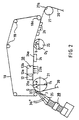
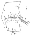
- Figure 1 is a schematic side view of a roll and blade gap former for carrying out the present invention in which the first forming roll is arranged inside the loop of the upper wire and the principal running direction of the twin-wire zone is substantially horizontal.
- Figure 2 is a schematic view of another embodiment of a former in which the first forming roll is arranged inside the loop of the lower wire.
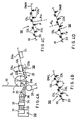
- Figure 3 is a schematic view of another embodiment of the former in which the support and loading blades in the MB-unit following after the first forming roll in the twin-wire zone are arranged in inverted positions in relation to the embodiment shown in Fig. 2 .
- Figure 4A is a view of a preferred embodiment of the initial part of the twin-wire zone in a former whose overall embodiment is substantially similar to the former shown in Fig. 1 , wherein important elements and features of the former are in use.
- Figure 4C is an illustration similar to Fig. 4B of a second embodiment of the twin-wire zone.
- Figure 4D is an illustration similar to Figs. 4B and 4C of a third embodiment of the twin-wire zone.
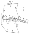
- Figure 5 is a schematic view of an embodiment of the roll and blade gap former in which the principal direction of the twin-wire zone is vertically upward.
- Figure 6 is a schematic view of the vertical former shown in Fig. 5 in which the support and loading members in the MB-unit following after the first forming roll are arranged in inverted positions compared to the embodiment shown in Fig. 5 .
- Figure 7 is a schematic view of an embodiment in which, unlike the embodiments shown in Figs. 5 and 6 , the first forming roll in the gap area and the second upper roll terminating the twin-wire zone are arranged inside the loop of the carrying wire.
- Figure 8 is a schematic view of a former in which the support and loading blades in the MB-unit following after the first forming roll are arranged in inverted positions compared to the embodiment shown in Fig. 7 .
- Figure 9A is a schematic illustration of an arrangement for measuring the pressure profile at the first forming roll.
- Figure 9B is a graphic illustration of results of measurement of the pressure profile at the first forming roll utilizing the arrangement shown in Fig. 9A .
- Figure 10A is a graphic illustration of z-directional distribution of anisotropy from a roll and blade former with various jet-to-wire ratios for a rush situation.
- Figure 10B is a graphic illustration of z-directional distribution of anisotropy from a roll and blade former with various jet-to-wire ratios for a drag situation.
- Figure 11A is a graphic illustration of the control of the fiber orientation in the paper web as a function of jet-to-wire ratio with different wrap angle sectors of the forming wires on the first forming roll.
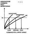
- Figure 11B is a graphic illustration of the orientation anisotropy in the paper web with different wrap angle sectors of the forming wires on the first forming roll.
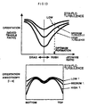
- Figure 13A is a graphic illustration of the control of fiber orientation in the paper web with different headbox types.
- Figure 13B is a graphic illustration of the orientation anisotropy in the paper web with different headbox types.
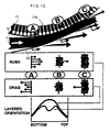
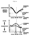
- Figure 14 illustrates the control of web formation and fiber orientation on "ROLL and BLADE" formers.
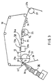
- Figure 16A is a schematic illustration of the area of the forming gap of a former.
- Figure 16B is a graphic illustration of formation as a function of the relative amount of water flow removed by the MB-unit or equivalent in the former shown in Fig. 16A .
- Figs. 1-4D are horizontal versions of the twin-wire former for carrying out the invention.
- the former in accordance with the invention comprises a lower wire 20 guided in a loop by guide rolls.
- the lower wire 20 is called the "carrying wire” because the web W follows this wire after the twin-wire zone.
- the former also comprises an upper wire 10 guided in a loop by rolls 18, 18a.
- the upper wire 10 is called the "covering wire” and, together with the lower wire 20, it defines a twin-wire zone whose principal running direction is substantially horizontal in the embodiments shown in Figs. 1-4D .
- the drainage of water from the paper web W that is being formed takes place through both wires 10, 20.
- the paper web W follows the lower wire 20 over a suction zone 27a of a wire suction roll 27 to a pick-up point to be passed onward, e.g., into a press section (not shown).
- the former includes a headbox 30 having a slice opening 37 from which a stock suspension jet J is fed into a wedge-shaped forming gap G defined by a convergence of the wires 10, 20.
- the headbox 30, which is shown schematically, may comprise, in the direction of flow of the stock suspension, an inlet header 31, a first bank of tubes such as a distributor manifold 32, an equalizing chamber 33, a second bank of tubes such as a set of turbulence tubes 34 and a narrowing slice channel 35 out of whose slice opening 37 the stock suspension jet J is discharged into the forming gap G.
- the headbox 30 that is used to expressly what is called headbox with vanes, i.e., in the slice channel 35, there are a number of turbulence vanes or turbulence generating vanes 36, arranged one above the other.
- the turbulence vanes 36 may be in the form of thin flexible plates and are fixed at an end next of the set of turbulence tubes 34 or plates so as to be freely floating and positioned in the stock suspension flow at their opposite end proximate the slice opening 37.
- turbulence vanes 36 By means of the turbulence vanes 36, a particularly high level of microturbulence and a high-energy turbulence state are produced in the stock suspension jet J discharged out of the slice opening 37, which has synergic effects with other specific features of the invention, which will be described later.
- the forming gap G is defined from above by the first forming roll 11, which is arranged inside the loop of the upper wire 10 and which is provided with a suction zone 11 a.
- the first forming roll 11 is arranged inside the loop of the upper wire 10 in Fig. 1
- the corresponding forming roll 21, which is provided with a similar suction zone 21 a is arranged inside the loop of the lower wire 20.
- the formers shown in Figs. 2 and 3 differ from the former shown in Fig. 1 also in the respect that in the embodiments shown in Figs. 2 and 3 , the run of the twin-wire zone is horizontal immediately after the first forming roll 21, whereas in Fig.
- the twin-wire zone is upwardly rising at an angle of about 20°.
- the run of the twin-wire zone is curved on a wrap angle sector a, in Figs. 1 and 4A in an upward direction and in Figs. 2 and 3 in a downward direction (depending on the location of the forming roll 11,21).
- the wrap angle sector a in Figs. 1 and 4A , there follows an upwardly inclined run of the twin-wire zone, in which, inside the loop of the lower wire 20, there is first a forming shoe 22 provided with a curved blade deck 22a and after that an MB-unit 50.
- the MB-unit 50 comprises drainage elements 13a and 23a arranged in an opposed relationship with the twin-wire zone running therebetween.
- Drainage element 13a includes fixed support blades or ribs and drainage element 23a includes movable support blades or ribs which are operatively loaded toward the fixed support blades by loading means to effect dewatering of the web.
- Other facets of the MB-unit 50 are discussed below.
- the MB-unit 50 is followed, inside the loop of the lower wire 20, by a second forming shoe 24 provided with a curved blade deck 24a.
- the curve radius R 1 of the first forming shoe 22 is typically selected to be from about 2 m to about 8 m and the curve radius R 2 of the second forming shoe 24 is also typically selected to be from about 2 m to about 8 m.
- the principal direction of the run of an adjustably loadable MB-blade zone defined between the first and the second forming shoes 22 and 24, and in which elements in the MB-unit are operative against an adjacent wire is substantially linear.
- the principal direction of the run of the MB-blade zone between the first and second forming shoes 22 and 24 is downwardly curved with a curve radius R a
- Fig. 4D it is upwardly curved with a curve radius R b .
- the formers illustrated in Figs. 2 and 3 are in most respects similar to one another with the exception of the relative positioning of drainage elements 13a, 13b and 23a, 23b in the MB-unit 50.
- the drainage element 13b of the MB-unit is arranged inside the loop of the upper wire 10 and comprises stationary support blades 13L which guide the twin-wire zone and which are seen more clearly in Figs. 4B, 4C and 4D .
- the drainage element 23b of the MB-unit 50 is arranged inside the loop of the lower wire 20 and comprises flexible loading blades 23L which are loadable by loading means (not shown) with an adjustable force F and which are also seen more clearly in Figs. 4B, 4C and 4D .
- the loading forces F of the loading blades 23L are produced in a manner in itself known by passing a medium of adjustable pressure, such as air or water, into loading hoses (not shown), which load the loading blades 23L against the wires 10,20 and against the stationary support blades 13L.
- the stationary support blades 13L are arranged in an alternating relationship with the flexible loading blades 23L as shown in Figs. 4B, 4C and 4D .
- the corresponding drainage elements 13a and 23a of the MB-unit are arranged in positions opposite in relation to the corresponding elements 13b and 23b shown in Fig. 2 .
- Fig. 4A shows an MB-unit in which the element 13b arranged inside the loop of the upper wire 10 comprises schematically illustrated position adjustment means such as position adjustment controls 13K, which are arranged in connection with the front and rear edges of the element 13b and by whose means the position and the loading of the element 13b in relation to the loading blades 23L ( Figs. 4C and 4D ) of the element 23b arranged inside the loop of the lower wire 20 can be adjusted.
- position adjustment means such as position adjustment controls 13K, which are arranged in connection with the front and rear edges of the element 13b and by whose means the position and the loading of the element 13b in relation to the loading blades 23L ( Figs. 4C and 4D ) of the element 23b arranged inside the loop of the lower wire 20 can be adjusted.
- the run of the twin-wire zone DWL is linear and upwardly inclined.
- the blades 13L arranged inside the loop of the upper wire 10 are stationary support blades
- the blades 23L arranged inside the loop of the lower wire 20 are flexible blades which can be loaded with adjustable forces F produced by means of a pressure medium.
- the pressure impulse of the set of blades and the formation and the drainage effect can be regulated.
- the environment of the elements 13b, 23b may be connected with sources of vacuum which intensify the drainage of water through the gap spaces between the sets of blades 13L and 23L.
- Fig. 4A shows a former including the unique combination of four particular characteristic features for carrying out the present invention, which particular features have a mutual combined effect and synergy, and which is described in more detail later, in particular with reference to Figs. 9A-16 .
- the first specific feature of the invention is the use of the turbulence vanes 36 in the slice channel 35 of the headbox 30 to cause the turbulence level in the stock suspension jet J discharged out of the slice opening 37 to be elevated and sufficiently high, i.e., above a situation in which turbulence vanes 36 are not used in a conventional headbox.
- a fourth specific feature of the invention is the use of the MB-unit 50 so that the twin-wire zone runs through the gap between the sets of blades 13L, 23L, one of which is loaded with adjustable forces F against the other, either along a linear path ( Fig. 4B ), along a downwardly curved path ( Fig. 4C ), or along an upwardly curved path ( Fig. 4D ).
- Figs. 5-8 illustrate vertical versions of the twin-wire former, wherein the run of the twin-wire zone is vertical and proceeds from the bottom towards the top, i.e., the forming gap is defined in a lowermost vertical position.
- the first forming roll 11 is arranged inside the loop of the covering wire 10
- the second upper forming roll 29 is arranged inside the loop of the carrying wire 20.
- a suction zone 29a of a second forming roll 29 arranged in the loop of the carrying wire 20 guarantees that, after the suction zone 29a, the web W follows the carrying wire 20 which is guided by guide rolls 28 and on which the web W is passed onto a pick-up roll 41.
- the web W is transferred onto a pick-up fabric 40 which carries the web W into the press section (not shown).
- the wire guide roll arranged opposite to the first forming roll 11,21 in the area of the forming gap G is denoted by the reference 21',11'.
- the diameter D 21 of the second forming suction roll 29 shown in Figs. 5-8 is typically selected in the range from about 1.0 m to about 1.8 m, preferably in the range from about 1.4 m to about 1.6 m.
- the paper web W can be passed directly from the wrap sector a of the first forming roll 11,21 to the MB-unit 50 without using a first forming shoe 12,22 provided with a curved blade deck or an equivalent drainage unit 12 provided with a planar blade deck 12a situated in between (as shown in Figs. 2 and 3 ).
- Figure 9A shows the area of the forming gap in a former in greater detail and the mounting of a surface mounted pressure transducer 1 and a pressure transducer 2 arranged between the wires.
- Fig. 9B shows that the drainage pattern through the forming zone on the first forming roll 11 actually has three distinct phases. Initially, a large discharge of water passes through the outer fabric 20 (which may be the covering wire or the carrying wire depending on the construction) in a straight line from the jet's impingement point IP against the fabric 20 (the initial zone). The jet J increases in thickness slightly at this point as a result of its deceleration upon entering a pressure zone created between the fabrics and 20. The initial discharge has only the bare fabric 20 as drainage resistance.
- the wrap angle a cannot be selected only with regard to orientation level however.
- the dimensioning criteria to attain good control of the balance of formation and retention is to set the forming roll 11,21 wrap angle a to drain approximately 70% of the headbox flow rate.
- this leads to the situation where the wood containing grades of newsprint and SC grades will be dimensioned with higher wrap angles than wood free grades. It is possible to exploit this fortuitous synergy since wood-containing grades are ideally made with higher orientation levels and therefore should have a higher wrap angle. Conversely, wood free grades normally require a lower level of orientation and should have a lower wrap angle.
- the standard type has a tube bundle turbulence generator or system and an open converging nozzle section.
- the high turbulence type headbox 30 uses the same tube bundle system 34 but has in addition turbulence vanes 36 attached at the outlets of the turbulence tubes in the tube bundle system 34 that extend into the nozzle or slice opening 37 area.
- the use of turbulence vanes 36 for increasing the turbulence is per se well known in the art.
- the length of the turbulence vanes 36 is but one parameter which enables the turbulence produced by the headbox to be adjusted.
- FIGS 10A and 10B show results from a roll and blade former for various jet-to-wire ratios.
- the minimum anisotropy occurred at a jet-to-wire ratio of 1.02, whereas this would be at 1.00 with a hybrid former of Fourdrinier.
- This 2% excess jet velocity is necessary so that after the jet J is decelerated entering the pressure zone between the wires 10 and 20, the jet speed will equal the wire speed.
- the notation of the X-axis is the distance in the z-direction of the web from the bottom side to the top side measured in grammage, i.e., it is the true distance in thickness in the case that the web density is uniform through the web thickness.
- the notation of the Y-axis i.e., the value of the anisotropy, is the amount of additional percentage of fibers in the main direction of orientation of the fibers than the amount of fibers in a perpendicular direction thereto. For example, when the anisotropy has a value of 0.3, there are 30% more fibers oriented in the main direction of fibers than in the perpendicular direction. Note that these axis notations also apply to the lowermost illustration in Fig. 10 as well as to Figs. 11B , 13B , 14 (lowermost illustration), 15A, 15B and 16B.
- the average anisotropy increases in magnitude as the jet-to-wire ratio is either decreased (drag) or increased (rush) from jet-to-wire ratio 1.02.
- the Z-direction anisotropy profile shape in drag is most often a simple curve having minimum anisotropy at the surfaces and maximum anisotropy at the sheet's center. In rush however, the layered anisotropy profile has a local minimum anisotropy at the center as well as at the edges; the maximum anisotropy occurs at the top middle and bottom middle sections.
- FIG. 10 One source of this different shape between rush and drag conditions is shown schematically in Figure 10 .
- the Z-direction jet-to-wire speed differences are shown throughout the forming zone in both rush and drag situations.
- Point C in Figure 10 is the point where the two fabrics 10,20 leave the forming roll 11. It is thought that the two fabrics 10,20 do not leave in a parallel line but rather the fabric 10 on the roll 11 side adheres to the roll 11 before releasing due to the presence of a vacuum zone 11a in the outgoing nip. This would cause a velocity change in the liquid center core at point C - as shown in Figure 10 .
- the velocity of the web greater than the speed of the wires at the center layer of the web is maintained somewhat.
- the wrap angle sector ends and the force exerted on the web decreases, the velocity of the center layer of the web is decreased.
- the edges of the web in the z-direction nave an even lower velocity than the edges of the web with respect to the velocity of the wires 10,20 in view of the resistance of the wires 10,20.
- the lower velocity of the web with respect to the wires at the center layer of the web is maintained somewhat.
- the wrap angle sector ends and the force exerted on the web decreases, the velocity of the center layer of the web is decreased with respect to the speed of the wires 10,20 even further.
- Figure 13B shows that in both rush and drag conditions the sheet's surfaces have a rather low level of anisotropy even at high shear (extreme rush or drag). If shear were the only consideration, the surface layers should be quite highly orientated. In practice, both drainage rate and initial turbulence in the headbox jet affect the level or orientation in the sheet's surface layers.
- the turbulence level depends on the flow rate and is not independently adjustable.
- the length of the vanes 36 can be varied, or some other criteria of the headbox adjusted to provide different amounts of turbulence.
- FIG. 13A The effects of this on orientation, measured through the machine direction/cross-machine direction tensile ratio, are shown in Figure 13A where medium turbulence means, e.g., shorter vanes 36, and high turbulence means, e.g., longer vanes, 36, i.e., there is a direct relationship between the length of the vanes and the amount of turbulence generated thereby.
- the initial turbulence level influences the anisotropy level over about 20% of the sheet thickness from the surfaces (40% in total) - see Figure 13B .
- the turbulence is probably dissipated before the center of the sheet is drained.
- headbox jet turbulence level to control orientation level, only works on gap formers equipped with a forming roll 11,21 as the first drainage element.
- the drainage rate has to be quite rapid to trap the turbulence near the surface layers before the turbulence dissipates.
- blade type gap formers the effects of altering the headbox jet's turbulence level will be very minor due to their slower drainage rate.
- FIG. 14 shows a comparison of the orientation and formation dependence on jet-to-wire ratio for a roll and blade former using a standard blade shoe 22 and a loadable MB-blade unit 50.
- the standard blade shoe 22 there are two optimum areas for formation, both of which give a highly orientated sheet.
- the optimum jet-to-wire ratio in rush is typically in the range 1.06 to 1.08 or, in drag, 0.96 to 0.98.
Landscapes
- Paper (AREA)
- Unwinding Webs (AREA)
- Advancing Webs (AREA)
- Control And Other Processes For Unpacking Of Materials (AREA)
Claims (4)
- Verfahren zum Steuern der Anisotropie einer bei einem Walzen- und Rakelspaltformer ausgebildeten Bahn, gekennzeichnet durch die folgenden Schritte:Erzeugen einer Turbulenz bei einem Ganzstoffsuspensionsstrahl (J) in einem Auslaufdüsenkanal (35) eines Stoffauflaufkasten (30) mittels Turbulenzerzeugungsflügeln (36), die in dem Auslaufdüsenkanal angeordnet sind,Ausstoßen des Ganzstoffsuspensionsstrahls (J) aus einer Auslaufdüsenöffnung (37) des Auslaufdüsenkanal (35) des Stoffauflaufkasten (30) und Richten des Ganzstoffsuspensionsstrahls (J) in einen Bahnbildungsspalt (G), der teilweise durch eine erste Bahnbildungswalze (11, 21) definiert ist, die einen Durchmesser (D1) hat, der größer oder gleich ungefähr 1,4 m ist, wobei der Ganzstoffsuspensionsstrahl (J) zu einer Konvergenz aus einem ersten und einem zweiten Sieb (10, 20) gerichtet wird, die eine Zwillingssiebzone nach dem Bahnbildungsspalt (G) definieren, wobei die erste Bahnbildungswalze (11, 21) in einer Schleife von entweder dem ersten oder dem zweiten Sieb (10, 20) angeordnet ist,Richten eines Laufes der Zwillingssiebzone nach dem Bahnbildungsspalt (G) in einer Kurve über einen Umschlingungswinkelsektor (a) der ersten Bahnbildungswalze (11, 21) mit einer Größe, die geringer als ungefähr 25° ist,Erzeugen eines Pulsationsdruckeffektes auf die Bahn (W) nach dem gekrümmten Lauf der Zwillingssiebzone über den Umschlingungswinkel (a) der Bahnbildungswalze (-11, 21) undEinstellen des Durchmessers (D1) der Bahnbildungswalze (11, 21), des Umschlingungswinkelsektors (a) der ersten Bahnbildungswalze (11, 21), einer Größe des Pulsationsdruckeffektes und eines Turbulenzbetrages bei dem Ganzstoffsuspensionsstrahl (J) relativ zueinander, um eine optimale Anisotropie in der Bahn vorzusehen.
- Verfahren gemäß Anspruch 1, dadurch gekennzeichnet, dass der Schritt des Erzeugens des Druckpulationseffektes die folgenden Schritte aufweist:Anordnen eines ersten Bahnbildungselements (13b, 23a) mit ortsfesten Bahnbildungsrakeln (13L) in einer der Siebschleifen (10, 20),Anordnen eines zweiten Bahnbildungselementes (13a, 23b) mit belastbaren Bahnbildungsrakeln (23L) in der anderen Siebschleife (10, 20) derart, dass sich die Rakeln (23L) bei dem zweiten Bahnbildungselement (13a, 23b) mit den Rakeln (13L) bei dem ersten Bahnbildungselement (13b, 23a) in der Laufrichtung der Bahn abwechseln, undEinstellen eines auf die Rakeln (23L) bei dem zweiten Bahnbildungselement (13a, 23b) aufgebrachten Druckimpulses, um die Belastung der Rakeln (23L) bei dem zweiten Bahnbildungselement (13a, 23b) zu ändern, um einen einstellbaren Ablauf- und Bahnbildungseffekt vorzusehen.
- Verfahren gemäß Anspruch 2, dadurch gekennzeichnet, dass dieses des weiteren den folgenden Schritt aufweist:Aufbringen eines Unterdrucks durch zwischen den Rakeln (13L, 23L) bei zumindest entweder dem ersten oder dem zweiten Bahnbildungselement (13a, 13b, 23a, 23b) definierte Spalträume, um das Ablaufen des Wassers durch die Spalträume zu intensivieren.
- Verfahren gemäß Anspruch 1, dadurch gekennzeichnet, dass der Ganzstoffsuspensionsstrahl (J) aus der Auslaufdüsenöffnung (37) des Auslaufdüsenkanals (35) des Stoffauflaufkasten (30) bei einer ersten Geschwindigkeit ausgestoßen wird, wobei das erste und das zweite Sieb (10, 20) so geführt werden, dass sie mit einer zweiten Geschwindigkeit laufen, wobei die erste Geschwindigkeit des Ganzstoffsuspensionsstrahls (J) relativ zu der zweiten Geschwindigkeit des ersten und des zweiten Siebes (10, 20) gesteuert wird, um dadurch ein Strahl-Sieb-Verhältnis zu definieren, dass das Verhältnis der zweiten Geschwindigkeit zu der ersten Geschwindigkeit bildet, wobei das Strahl-Sieb-Verhältnis relativ zu dem Durchmesser (D1) der ersten Bahnbildungswalze (11, 21), den Umschlingungswinkelsektor (a) der ersten Bahnbildunswalze (11, 21), der Größe des Pulsationsdruckeffektes und des Turbulenzbetrages bei dem Ganzstoffsuspensionsstrahl (J) eingestellt wird, um eine optimale Anisotropie in der Bahn vorzusehen.
Applications Claiming Priority (3)
| Application Number | Priority Date | Filing Date | Title |
|---|---|---|---|
| US08/661,657 US5798024A (en) | 1996-06-11 | 1996-06-11 | Controlling web anistropy in a roll and blade twin-wire gap former |
| US661657 | 1996-06-11 | ||
| PCT/FI1997/000362 WO1997047803A1 (en) | 1996-06-11 | 1997-06-10 | Roll and blade twin-wire gap former for a paper machine |
Publications (3)
| Publication Number | Publication Date |
|---|---|
| EP0853703A1 EP0853703A1 (de) | 1998-07-22 |
| EP0853703B1 EP0853703B1 (de) | 2001-10-10 |
| EP0853703B2 true EP0853703B2 (de) | 2009-01-07 |
Family
ID=24654539
Family Applications (1)
| Application Number | Title | Priority Date | Filing Date |
|---|---|---|---|
| EP97926023A Expired - Lifetime EP0853703B2 (de) | 1996-06-11 | 1997-06-10 | Verfahren zur einstellung der anisotropie einer papierbahn |
Country Status (9)
| Country | Link |
|---|---|
| US (1) | US5798024A (de) |
| EP (1) | EP0853703B2 (de) |
| JP (1) | JP3297057B2 (de) |
| KR (1) | KR100423180B1 (de) |
| AT (1) | ATE206780T1 (de) |
| BR (1) | BR9702313A (de) |
| CA (1) | CA2228259C (de) |
| DE (1) | DE69707256T3 (de) |
| WO (1) | WO1997047803A1 (de) |
Families Citing this family (19)
| Publication number | Priority date | Publication date | Assignee | Title |
|---|---|---|---|---|
| FI981098A7 (fi) * | 1998-05-18 | 1999-11-19 | Valmet Corp | Paperikoneen kaksiviirainen tela-kiraformeri |
| DE10012342A1 (de) * | 2000-03-14 | 2001-09-20 | Voith Paper Patent Gmbh | Doppelsiebformer |
| US6860030B1 (en) * | 2000-11-15 | 2005-03-01 | Voith Paper, Inc. | Control system for gap measuring |
| FI109299B (fi) * | 2001-01-22 | 2002-06-28 | Metso Paper Inc | Kaksiviiraformeri |
| DE10106731A1 (de) * | 2001-02-14 | 2002-08-22 | Voith Paper Patent Gmbh | Doppelsiebformer zur Herstellung einer Faserstoffbahn aus einer Faserstoffsuspension |
| DE10161056A1 (de) * | 2001-12-12 | 2003-06-26 | Voith Paper Patent Gmbh | Siebpartie |
| ATE378470T1 (de) * | 2002-03-01 | 2007-11-15 | Voith Patent Gmbh | Verfahren und system zur steuerung der papierformation |
| CN100371528C (zh) * | 2002-08-23 | 2008-02-27 | 美卓造纸机械公司 | 纸幅或纸板幅在双网成型器或成型器的双网区中的成型 |
| US7789995B2 (en) | 2002-10-07 | 2010-09-07 | Georgia-Pacific Consumer Products, LP | Fabric crepe/draw process for producing absorbent sheet |
| US6821392B2 (en) * | 2003-02-20 | 2004-11-23 | Metso Paper, Inc. | Headbox sealing device |
| CN1886555B (zh) * | 2003-12-22 | 2011-01-12 | 阿斯顿约翰逊公司 | 用于造纸机的混合型成形部 |
| MXPA06005684A (es) * | 2003-12-22 | 2006-08-17 | Astenjohnson Inc | Seccion de formacion tipo separacion para una maquina de fabricacion de papel tela doble. |
| JP4913510B2 (ja) * | 2006-09-05 | 2012-04-11 | 横河電機株式会社 | シミュレーション方法、繊維配向制御方法、及び繊維配向制御装置 |
| DE102006049078A1 (de) * | 2006-10-13 | 2008-04-17 | Voith Patent Gmbh | Vorrichtung und Verfahren zur Herstellung einer Faserstoffbahn |
| DE102006049026A1 (de) * | 2006-10-13 | 2008-04-17 | Voith Patent Gmbh | Vorrichtung und Verfahren zur Herstellung einer Faserstoffbahn |
| DE102006049025A1 (de) | 2006-10-13 | 2008-04-17 | Voith Patent Gmbh | Vorrichtung und Verfahren zur Herstellung einer Faserstoffbahn |
| JP5270663B2 (ja) * | 2008-03-21 | 2013-08-21 | 日本製紙株式会社 | 塗工紙の製造方法 |
| KR20160063770A (ko) | 2014-11-27 | 2016-06-07 | 주식회사 제이엘서피스 | 내식성이 우수한 건식 확산 코팅 조성물의 제조방법 |
| SE540011C2 (en) * | 2015-05-19 | 2018-02-27 | Valmet Oy | A method of making a structured fibrous web and a creped fibrous web |
Citations (3)
| Publication number | Priority date | Publication date | Assignee | Title |
|---|---|---|---|---|
| US3963562A (en) † | 1974-01-14 | 1976-06-15 | Lodding Engineering Corporation | Slurry distributor |
| US4941950A (en) † | 1989-07-26 | 1990-07-17 | Beloit Corporation | Headbox with grooved trailing element |
| DE2857473C2 (de) † | 1977-10-11 | 1992-07-30 | The Procter & Gamble Co., Cincinnati, Ohio, Us |
Family Cites Families (13)
| Publication number | Priority date | Publication date | Assignee | Title |
|---|---|---|---|---|
| US3843470A (en) * | 1970-08-31 | 1974-10-22 | Beloit Corp | Flexible trailing elements in a paper-making machine headbox having projections thereon extending into the slurry flow |
| US3923593A (en) * | 1971-12-03 | 1975-12-02 | Beloit Corp | Multiple ply web former with divided slice chamber |
| US5393378A (en) * | 1989-05-31 | 1995-02-28 | Ishikawajima-Harima Jukogyo Kabushiki Kaishi | Method for measuring and controlling fiber variations in paper sheet |
| DE4026953C2 (de) * | 1990-01-26 | 1995-11-30 | Escher Wyss Gmbh | Entwässerungsvorrichtung und Verfahren zur Entwässerung an einem Doppelsiebformer |
| US5034098A (en) * | 1990-02-23 | 1991-07-23 | Beloit Corporation | Method of forming a paper web |
| FI91788C (fi) * | 1990-09-12 | 1994-08-10 | Valmet Paper Machinery Inc | Paperikoneen kaksiviirainen rainanmuodostusosa |
| FI93032C (fi) * | 1991-03-15 | 1995-02-10 | Valmet Paper Machinery Inc | Paperikoneen kaksiviirainen rainanmuodostusosa |
| US5211814A (en) * | 1991-05-31 | 1993-05-18 | Valmet Paper Machinery Inc. | Wire loading device in a paper machine |
| US5129988A (en) * | 1991-06-21 | 1992-07-14 | Kimberly-Clark Corporation | Extended flexible headbox slice with parallel flexible lip extensions and extended internal dividers |
| FI920228A0 (fi) * | 1992-01-17 | 1992-01-17 | Valmet Paper Machinery Inc | Banformningsparti foer pappersmaskin. |
| SE501332C2 (sv) | 1993-05-27 | 1995-01-16 | Valmet Karlstad Ab | Sätt att forma en tissuepappersbana |
| FI103995B (fi) * | 1993-06-17 | 1999-10-29 | Valmet Paper Machinery Inc | Menetelmä ja laite sekä säätöjärjestely paperikoneessa paperirainan poikittaisen profiilin hallinnassa |
| FI953984A7 (fi) * | 1995-08-24 | 1997-02-25 | Metso Paper Inc | Paperikoneen rainanmuodostusosa |
-
1996
- 1996-06-11 US US08/661,657 patent/US5798024A/en not_active Expired - Lifetime
-
1997
- 1997-06-10 CA CA002228259A patent/CA2228259C/en not_active Expired - Fee Related
- 1997-06-10 BR BR9702313A patent/BR9702313A/pt not_active IP Right Cessation
- 1997-06-10 AT AT97926023T patent/ATE206780T1/de active
- 1997-06-10 KR KR10-1998-0701021A patent/KR100423180B1/ko not_active Expired - Fee Related
- 1997-06-10 DE DE69707256T patent/DE69707256T3/de not_active Expired - Lifetime
- 1997-06-10 WO PCT/FI1997/000362 patent/WO1997047803A1/en not_active Ceased
- 1997-06-10 JP JP50125198A patent/JP3297057B2/ja not_active Expired - Fee Related
- 1997-06-10 EP EP97926023A patent/EP0853703B2/de not_active Expired - Lifetime
Patent Citations (3)
| Publication number | Priority date | Publication date | Assignee | Title |
|---|---|---|---|---|
| US3963562A (en) † | 1974-01-14 | 1976-06-15 | Lodding Engineering Corporation | Slurry distributor |
| DE2857473C2 (de) † | 1977-10-11 | 1992-07-30 | The Procter & Gamble Co., Cincinnati, Ohio, Us | |
| US4941950A (en) † | 1989-07-26 | 1990-07-17 | Beloit Corporation | Headbox with grooved trailing element |
Non-Patent Citations (2)
| Title |
|---|
| James L. Ewald, Tappi Proceedings, 1989, pp 3-11 † |
| Scott B. Pantaleo, Tappi Journal Vol. 78, Nov 11 1995, pp 89-95 † |
Also Published As
| Publication number | Publication date |
|---|---|
| DE69707256T2 (de) | 2002-07-11 |
| WO1997047803A1 (en) | 1997-12-18 |
| KR100423180B1 (ko) | 2004-07-19 |
| DE69707256D1 (de) | 2001-11-15 |
| EP0853703B1 (de) | 2001-10-10 |
| ATE206780T1 (de) | 2001-10-15 |
| KR19990036353A (ko) | 1999-05-25 |
| DE69707256T3 (de) | 2009-07-16 |
| CA2228259A1 (en) | 1997-12-18 |
| EP0853703A1 (de) | 1998-07-22 |
| JPH11504997A (ja) | 1999-05-11 |
| US5798024A (en) | 1998-08-25 |
| CA2228259C (en) | 1999-12-07 |
| BR9702313A (pt) | 1999-03-09 |
| JP3297057B2 (ja) | 2002-07-02 |
Similar Documents
| Publication | Publication Date | Title |
|---|---|---|
| EP0853703B2 (de) | Verfahren zur einstellung der anisotropie einer papierbahn | |
| US3994774A (en) | Twin-wire paper machine adjustable to single-wire machine | |
| CA1084318A (en) | Microturbulence generator for papermachine headbox | |
| US6372091B2 (en) | Method and apparatus for forming a paper web | |
| CA2104230A1 (en) | Twin-wire former | |
| EP0373133A2 (de) | Verfahren und Vorrichtung zur Herstellung einer Papier- oder Pappbahn | |
| EP2035622B1 (de) | FORMIERPARTIE und zugehöriges Verfahren | |
| US5599427A (en) | Twin-wire web former in a paper machine | |
| US5552021A (en) | Method, device and arrangement for regulating the control of a transverse profile of a paper web in a paper machine | |
| US6776877B2 (en) | Twin wire former for the production of a fiber web from a fiber suspension | |
| US5833809A (en) | Twin-wire former | |
| GB2094364A (en) | Methods and apparatus for forming a multi-layered paper web | |
| CA2151645C (en) | Hybrid former for a paper machine | |
| EP0488058A1 (de) | Formierzone in der Zweisiebenformierpartie einer Papiermaschine | |
| CA2207971C (en) | Three-layer headbox | |
| EP0700472B1 (de) | Verfahren zur herstellung von tissuepapier | |
| EP1361309A1 (de) | Verfahren zur Regelung der Qualität einer Papierbahn | |
| CA2277979C (en) | Roll and blade twin-wire gap former for a paper machine | |
| US5409575A (en) | Two-wire web-forming section of a paper machine | |
| US6464835B1 (en) | Equipment and method in a twin-wire former | |
| CA2300280C (en) | Apparatus and method of generating stock turbulence in a fourdrinier forming section | |
| US6962647B2 (en) | Headbox for a paper machine, board machine, pulp machine or equivalent | |
| US20240060238A1 (en) | Inclined-wire former and method of producing a fibrous web | |
| Norman | 10 Web Forming |
Legal Events
| Date | Code | Title | Description |
|---|---|---|---|
| PUAI | Public reference made under article 153(3) epc to a published international application that has entered the european phase |
Free format text: ORIGINAL CODE: 0009012 |
|
| 17P | Request for examination filed |
Effective date: 19980127 |
|
| AK | Designated contracting states |
Kind code of ref document: A1 Designated state(s): AT DE FI FR GB IT SE |
|
| 17Q | First examination report despatched |
Effective date: 20000411 |
|
| GRAG | Despatch of communication of intention to grant |
Free format text: ORIGINAL CODE: EPIDOS AGRA |
|
| GRAG | Despatch of communication of intention to grant |
Free format text: ORIGINAL CODE: EPIDOS AGRA |
|
| GRAH | Despatch of communication of intention to grant a patent |
Free format text: ORIGINAL CODE: EPIDOS IGRA |
|
| GRAH | Despatch of communication of intention to grant a patent |
Free format text: ORIGINAL CODE: EPIDOS IGRA |
|
| RAP1 | Party data changed (applicant data changed or rights of an application transferred) |
Owner name: METSO PAPER, INC. |
|
| GRAA | (expected) grant |
Free format text: ORIGINAL CODE: 0009210 |
|
| AK | Designated contracting states |
Kind code of ref document: B1 Designated state(s): AT DE FI FR GB IT SE |
|
| REF | Corresponds to: |
Ref document number: 206780 Country of ref document: AT Date of ref document: 20011015 Kind code of ref document: T |
|
| REF | Corresponds to: |
Ref document number: 69707256 Country of ref document: DE Date of ref document: 20011115 |
|
| REG | Reference to a national code |
Ref country code: GB Ref legal event code: IF02 |
|
| ET | Fr: translation filed | ||
| PLBQ | Unpublished change to opponent data |
Free format text: ORIGINAL CODE: EPIDOS OPPO |
|
| PLBI | Opposition filed |
Free format text: ORIGINAL CODE: 0009260 |
|
| 26 | Opposition filed |
Opponent name: VOITH PAPER PATENT GMBH Effective date: 20020709 |
|
| PLBF | Reply of patent proprietor to notice(s) of opposition |
Free format text: ORIGINAL CODE: EPIDOS OBSO |
|
| PLBF | Reply of patent proprietor to notice(s) of opposition |
Free format text: ORIGINAL CODE: EPIDOS OBSO |
|
| PLCK | Communication despatched that opposition was rejected |
Free format text: ORIGINAL CODE: EPIDOSNREJ1 |
|
| APBP | Date of receipt of notice of appeal recorded |
Free format text: ORIGINAL CODE: EPIDOSNNOA2O |
|
| APBQ | Date of receipt of statement of grounds of appeal recorded |
Free format text: ORIGINAL CODE: EPIDOSNNOA3O |
|
| APAA | Appeal reference recorded |
Free format text: ORIGINAL CODE: EPIDOS REFN |
|
| APAH | Appeal reference modified |
Free format text: ORIGINAL CODE: EPIDOSCREFNO |
|
| APBU | Appeal procedure closed |
Free format text: ORIGINAL CODE: EPIDOSNNOA9O |
|
| RIC2 | Information provided on ipc code assigned after grant |
Ipc: D21F 9/00 20060101ALI20070413BHEP Ipc: D21F 11/02 20060101AFI20070413BHEP |
|
| RTI2 | Title (correction) |
Free format text: METHOD FOR CONTROLLING THE ANISOTROPY OF A PAPER WEB |
|
| PUAH | Patent maintained in amended form |
Free format text: ORIGINAL CODE: 0009272 |
|
| STAA | Information on the status of an ep patent application or granted ep patent |
Free format text: STATUS: PATENT MAINTAINED AS AMENDED |
|
| 27A | Patent maintained in amended form |
Effective date: 20090107 |
|
| AK | Designated contracting states |
Kind code of ref document: B2 Designated state(s): AT DE FI FR GB IT SE |
|
| REG | Reference to a national code |
Ref country code: SE Ref legal event code: RPEO |
|
| PGFP | Annual fee paid to national office [announced via postgrant information from national office to epo] |
Ref country code: FI Payment date: 20120613 Year of fee payment: 16 Ref country code: SE Payment date: 20120621 Year of fee payment: 16 Ref country code: GB Payment date: 20120622 Year of fee payment: 16 Ref country code: FR Payment date: 20120705 Year of fee payment: 16 |
|
| PGFP | Annual fee paid to national office [announced via postgrant information from national office to epo] |
Ref country code: IT Payment date: 20130625 Year of fee payment: 17 |
|
| PG25 | Lapsed in a contracting state [announced via postgrant information from national office to epo] |
Ref country code: SE Free format text: LAPSE BECAUSE OF NON-PAYMENT OF DUE FEES Effective date: 20130611 |
|
| REG | Reference to a national code |
Ref country code: SE Ref legal event code: EUG |
|
| GBPC | Gb: european patent ceased through non-payment of renewal fee |
Effective date: 20130610 |
|
| PG25 | Lapsed in a contracting state [announced via postgrant information from national office to epo] |
Ref country code: FI Free format text: LAPSE BECAUSE OF NON-PAYMENT OF DUE FEES Effective date: 20130610 |
|
| REG | Reference to a national code |
Ref country code: FR Ref legal event code: ST Effective date: 20140228 |
|
| PG25 | Lapsed in a contracting state [announced via postgrant information from national office to epo] |
Ref country code: GB Free format text: LAPSE BECAUSE OF NON-PAYMENT OF DUE FEES Effective date: 20130610 |
|
| PG25 | Lapsed in a contracting state [announced via postgrant information from national office to epo] |
Ref country code: FR Free format text: LAPSE BECAUSE OF NON-PAYMENT OF DUE FEES Effective date: 20130701 |
|
| PGFP | Annual fee paid to national office [announced via postgrant information from national office to epo] |
Ref country code: AT Payment date: 20140611 Year of fee payment: 18 Ref country code: DE Payment date: 20140619 Year of fee payment: 18 |
|
| PG25 | Lapsed in a contracting state [announced via postgrant information from national office to epo] |
Ref country code: IT Free format text: LAPSE BECAUSE OF NON-PAYMENT OF DUE FEES Effective date: 20140610 |
|
| REG | Reference to a national code |
Ref country code: DE Ref legal event code: R119 Ref document number: 69707256 Country of ref document: DE |
|
| REG | Reference to a national code |
Ref country code: AT Ref legal event code: MM01 Ref document number: 206780 Country of ref document: AT Kind code of ref document: T Effective date: 20150610 |
|
| PG25 | Lapsed in a contracting state [announced via postgrant information from national office to epo] |
Ref country code: DE Free format text: LAPSE BECAUSE OF NON-PAYMENT OF DUE FEES Effective date: 20160101 |
|
| PG25 | Lapsed in a contracting state [announced via postgrant information from national office to epo] |
Ref country code: AT Free format text: LAPSE BECAUSE OF NON-PAYMENT OF DUE FEES Effective date: 20150610 |