EP0853322B1 - Elektrischer Übergang mit niedrigem Widerstand in strombegrenzenden Polymeren, erzielt durch Plasmaverfahren - Google Patents
Elektrischer Übergang mit niedrigem Widerstand in strombegrenzenden Polymeren, erzielt durch Plasmaverfahren Download PDFInfo
- Publication number
- EP0853322B1 EP0853322B1 EP97309495A EP97309495A EP0853322B1 EP 0853322 B1 EP0853322 B1 EP 0853322B1 EP 97309495 A EP97309495 A EP 97309495A EP 97309495 A EP97309495 A EP 97309495A EP 0853322 B1 EP0853322 B1 EP 0853322B1
- Authority
- EP
- European Patent Office
- Prior art keywords
- current limiting
- conductive
- polymer composition
- electrodes
- polymer
- Prior art date
- Legal status (The legal status is an assumption and is not a legal conclusion. Google has not performed a legal analysis and makes no representation as to the accuracy of the status listed.)
- Expired - Lifetime
Links
Images

Classifications
-
- H—ELECTRICITY
- H01—ELECTRIC ELEMENTS
- H01C—RESISTORS
- H01C17/00—Apparatus or processes specially adapted for manufacturing resistors
- H01C17/28—Apparatus or processes specially adapted for manufacturing resistors adapted for applying terminals
-
- H—ELECTRICITY
- H01—ELECTRIC ELEMENTS
- H01C—RESISTORS
- H01C1/00—Details
- H01C1/14—Terminals or tapping points specially adapted for resistors; Arrangements of terminals or tapping points on resistors
- H01C1/1406—Terminals or electrodes formed on resistive elements having positive temperature coefficient
-
- H—ELECTRICITY
- H01—ELECTRIC ELEMENTS
- H01C—RESISTORS
- H01C7/00—Non-adjustable resistors formed as one or more layers or coatings; Non-adjustable resistors made from powdered conducting material or powdered semi-conducting material with or without insulating material
- H01C7/02—Non-adjustable resistors formed as one or more layers or coatings; Non-adjustable resistors made from powdered conducting material or powdered semi-conducting material with or without insulating material having positive temperature coefficient
- H01C7/027—Non-adjustable resistors formed as one or more layers or coatings; Non-adjustable resistors made from powdered conducting material or powdered semi-conducting material with or without insulating material having positive temperature coefficient consisting of conducting or semi-conducting material dispersed in a non-conductive organic material
-
- Y—GENERAL TAGGING OF NEW TECHNOLOGICAL DEVELOPMENTS; GENERAL TAGGING OF CROSS-SECTIONAL TECHNOLOGIES SPANNING OVER SEVERAL SECTIONS OF THE IPC; TECHNICAL SUBJECTS COVERED BY FORMER USPC CROSS-REFERENCE ART COLLECTIONS [XRACs] AND DIGESTS
- Y10—TECHNICAL SUBJECTS COVERED BY FORMER USPC
- Y10T—TECHNICAL SUBJECTS COVERED BY FORMER US CLASSIFICATION
- Y10T29/00—Metal working
- Y10T29/49—Method of mechanical manufacture
- Y10T29/49002—Electrical device making
- Y10T29/49082—Resistor making
- Y10T29/49083—Heater type
-
- Y—GENERAL TAGGING OF NEW TECHNOLOGICAL DEVELOPMENTS; GENERAL TAGGING OF CROSS-SECTIONAL TECHNOLOGIES SPANNING OVER SEVERAL SECTIONS OF THE IPC; TECHNICAL SUBJECTS COVERED BY FORMER USPC CROSS-REFERENCE ART COLLECTIONS [XRACs] AND DIGESTS
- Y10—TECHNICAL SUBJECTS COVERED BY FORMER USPC
- Y10T—TECHNICAL SUBJECTS COVERED BY FORMER US CLASSIFICATION
- Y10T29/00—Metal working
- Y10T29/49—Method of mechanical manufacture
- Y10T29/49002—Electrical device making
- Y10T29/49082—Resistor making
- Y10T29/49101—Applying terminal
Definitions
- This invention relates to electrical devices based on current limiting PTC polymer devices, and in particular to electrical circuit protection devices comprising a current limiting PTC polymer device composed of a conductive polymer composition in combination with suitable electrodes.
- the invention also concerns the physical and electrical interface between the conductive polymer composition and the electrodes combined thereto. Specifically, the invention concerns an interface between a conductive polymer composition and an electrode resulting in a low contact resistance.
- the current limiting polymer compositions generally include conductive particles, such as carbon black, graphite or metal particles, dispersed in a polymer matrix, such as thermoplastic polymer, elastomeric polymer or thermosetting polymer.
- PTC behavior in a current limiting polymer composition is characterized by the material undergoing a sharp increase in resistivity as its temperature rises above a particular value otherwise known as the anomaly or switching temperature, T s .
- Materials exhibiting PTC behavior are useful in a number of applications including electrical circuit protection devices in which the current passing through a circuit is controlled by the temperature of a PTC element forming part of that circuit.
- Particularly useful devices comprising current limiting polymer compositions are electrical circuit protection devices.
- Such circuit protection devices usually contain a current limiting polymer device comprised of two electrodes embedded in a current limiting polymer composition.
- the circuit protection devices When connected to a circuit, the circuit protection devices have a relatively low resistance under normal operating conditions of the circuit, but are tripped, that is, converted into a high resistance state when a fault condition, for example, excessive current or temperature, occurs.
- a fault condition for example, excessive current or temperature
- T s transition temperature or switching temperature
- a current limiting polymer composition is attached in some manner to a source of electrical power.
- This is generally provided by what is referred to in the art as an electrode which is in contact with the current limiting polymer composition and which is connected to a source of electrical power.
- the interface in these devices between the current limiting polymer composition and the metal electrode presents certain problems which limit the range of applications in which such devices can be reliably implemented commercially. For example, the avoidance of excessive current concentrations at any spot near the electrodes of the device presents problems, as does the provision of electrodes in a form which will reliably distribute the current over a suitable cross-sectional area of the current limiting polymer composition of the device and without variations of such distribution on repeated cycles of operation of the device.
- metal electrodes may lead to some degree of electrical non-uniformity; if the surface of the electrode closest to the other electrode has any imperfections, this can lead to electrical stress concentration which will cause poor performance. This problem is particularly serious when the current limiting polymer composition exhibits PTC behavior, since it can cause creation of a hot zone adjacent to the electrode; it also becomes increasingly serious as the distance between the electrodes gets smaller.
- the electrodes which have been used in such current limiting PTC polymer devices include solid and stranded wires, wire rovings, metal foils, expanded metal, perforated metal sheets, etc.
- a variety of methods have been developed for connecting the electrodes to the current limiting polymer composition.
- Taylor discloses a method for laminating metal foil electrodes to the current limiting polymer composition through the use of pressure, heat and time. Taylor also discloses the optional use of an electrically conductive adhesive to help bind the electrode to the current limiting polymer composition.
- Kleiner, et al. 253 & '475 disclose the use of electrodes with microrough surfaces. Namely, Kleiner, et al., teaches the use of electrodes that have a roughened surface obtained by removal of material from the surface of a smooth electrode, e.g. by etching; by chemical reaction on the surface of a smooth electrode, e.g. by galvanic deposition; or by deposition of a microrough layer of the same or a different material on the surface of the electrode.
- JP 63-312601 A discloses a conductive polymer PTC resistance element which includes two surfaces roughened by physicochemical means and which includes metal films deposited on the surface by sputtering.
- the current limiting polymer composition plastically deforms to make intimate contact with the electrodes.
- a thin layer of polymer may cover a large percentage of the contact area between the electrodes and the current limiting polymer composition. This thin layer of polymer will prevent direct contact between the conductive filler particles in the current limiting polymer composition and the electrodes. This factor limits the decrease in device resistance obtainable through the application of pressure to connect electrodes to the current limiting polymer composition.
- the resulting device requires a large package and consequently has to be mounted externally to the circuit breaker. Therefore, it would be desirable to have a method for attaching electrodes to current limiting polymer compositions which would provide for a compact geometry and which would not require high spring pressure.
- a low contact resistance relative to the overall device resistance is desirable for two main reasons. First, the joule heating will occur in the bulk of the current limiting polymer composition thus preventing arcing at the electrode-composition interface. Such arcing results in electrode delamination or a thermal/electrical break down in the electrode composition interface. Second, the lower the overall device resistance the higher the steady state current ratings obtainable for the device.
- the invention is defined by the method with the features of claim 1 and the device with the features of claim 6.
- the conductive polymer composition can include thermoplastic polymer, elastomeric polymer or thermosetting polymer.
- the conductive filler particles can include carbon black, graphite, metal powders, metal salts, conductive metal oxides and mixtures thereof.
- the material used to metallize the at least two metallized surfaces of the conductive polymer composition include tantalum, tungsten, titanium, chromium, molybdenum, vanadium, zirconium, aluminium, silver, copper, nickel, gold, brass, zinc, mixtures thereof and plated metals, i.e. silver plated copper.
- This conductive polymer composition can also include non-conductive fillers such as flame retardants, arc-suppression agents, radiation cross-linking agents, plasticizers, antioxidents, and other adjuvants. These conductive polymer compositions can further be cross-linked by radiation, chemical cross-linking, or heat cross-linking for improved electrical properties.
- non-conductive fillers such as flame retardants, arc-suppression agents, radiation cross-linking agents, plasticizers, antioxidents, and other adjuvants.
- These conductive polymer compositions can further be cross-linked by radiation, chemical cross-linking, or heat cross-linking for improved electrical properties.
- One embodiment of the invention provides an electrical device which comprises (a) a conductive polymer composition comprising a polymer with conductive particles dispersed therein, wherein at least two surfaces of said conductive polymer composition are enriched with said conductive particles, and (b) at least two electrodes attached to said conductive polymer composition at said at least two surfaces enriched with conductive particles.
- Such devices are characterized by being relatively conductive when used as a circuit component carrying normal current but which exhibit a very sharp increase in resistivity and reversibly transform into being relatively non-conductive when the temperature of the device increases above a switching temperature or switching temperature range, T s , due to resistive Joule heating (I 2 R) generated from a fault current.
- These electrical devices are particularly useful as PTC elements in electrical circuit protection devices.
- the conductive polymer compositions can be surface treated to provide at least two conductive particle enriched surfaces. Such surface treatment entails plasma etching of the surfaces of the conductive polymer compositions to be enriched.
- plasma etching processes are known. Of the various known etching processes, corona etching may be particularly useful with the invention. Corona etching in air at atmospheric pressure may be as effective as etching at reduced pressures while being more cost effective and easier to implement on a manufacturing scale compared to conventional plasma etching processes.
- Plasma etching involves the selective removal of polymer molecules from the treated surfaces of the conductive polymer composition using plasma processing. Basically, plasma etching entails ion bombardment as well as chemical reactions of the surface of the conductive polymer composition with mobile ions. Because the polymer molecules are more readily energized by the ion bombardment, the plasma etching results in a greater loss of polymer molecules from the surface of the conductive polymer composition compared to the loss of atoms or molecules of the conductive particles. Accordingly, the plasma etched surfaces of the conductive polymer composition has a higher concentration of conductive particles exposed (i.e., no polymer film covering the surface of the particles on the treated surface of the conductive polymer composition) than do the untreated surfaces.
- conductive particles i.e., carbon black.
- the increase in the concentration of conductive particles at the surface of the conductive polymer composition results in a significant decrease in the contact resistance between said treated surface and the electrode subsequently attached thereto.
- the greater the area of real contact between the conductive particles and the electrode the lower the contact resistance.
- the treatment of the surface of the conductive polymer composition results in an increase in the area of real contact between said composition and the electrode subsequently attached thereto, and hence, reduces the contact resistance.
- plasma etching of the conductive polymer composition results in a two fold decrease in the contact resistance of the current limiting PTC polymer devices of the invention.
- Selected areas on the surface of the conductive polymer compositions may also optionally be metallized.
- the metals used to metallize the conductive polymer composition may be capable of reacting with the conductive carbon particles to form a carbide; preferably the metal should be selected from the group comprising tantalum, tungsten, titanium, chromium molybdenum, vanadium, zirconium, aluminum, silver, nickel and mixtures thereof; more preferably from a group of metals which exhibit both a low oxidation and the tendency to form highly conductive oxides, i.e., Ti, Cr or some form of hybrid which reacts to form a highly conductive oxide, i.e., WTiC 2.
- non-carbide forming metals may be used provided that they maintain long term ( ⁇ 10 year) conductivity, i.e. silver, nickel, silver plating over copper, and silver plating
- the surface of the conductive polymer composition can be metallized using a deposition process known in the art as plasma sputtering.
- plasma spray techniques in air at atmospheric pressure may be used to metallize the surfaces of conductive polymer compositions on a manufacturing scale at reduced cost compared to conventional plasma sputtering processes.
- the plasma sputtering process entails bombarding a metal target, i.e., silver, with argon ions, or similar ions such that metal atoms are liberated from the surface of the target and impinge on the surface of the conductive polymer composition.
- the selected surfaces of the conductive polymer composition can be optionally plasma etched by the process described above.
- the plasma etching and plasma sputtering processes be performed in the same apparatus. It is most preferable that the interior cavity of the apparatus not be exposed to atmospheric gases between the etching and sputtering processes. Such procedure is preferred because atmospheric gases may contaminate the sample surface.
- the polymers suitable for use in preparing the conductive polymer compositions can be thermoplastic, elastomeric or thermosetting resins or blends thereof; preferably thermoplastic polymers; most preferably polyethylene polymers.
- Thermoplastic polymers suitable for may be crystalline or non-crystalline.
- Illustrative examples are polyolefins, such as polyethylene or polypropylene, copolymers (including terpolymers, etc.) of olefins such as ethylene and propylene, with each other and with other monomers such as vinyl esters, acids or esters of ⁇ , ⁇ -unsaturated organic acids or mixtures thereof, halogenated vinyl or vinylidene polymers such as polyvinyl chloride, polyvinylidene chloride, polyvinyl fluoride, polyvinylidene fluoride and copolymers of these monomers with each other or with other unsaturated monomers, polyesters, such as poly(hexamethylene adipate or sebacate), poly(ethylene terephthalate) and poly(tetramethylene terephthalate), polyamides such as Nylon-6, Nylon-6,6 Nylon-6,10 and the "Versamids" (condensation
- Suitable elastomeric resins include rubbers, elastomeric gums and thermoplastic elastomers.
- elastomeric gum refers to a polymer which is non-crystalline and which exhibits rubbery or elastomeric characteristics after being cross-linked.
- thermoplastic elastomer refers to a material which exhibits, in a certain temperature range, at least some elastomer properties; such materials generally contain thermoplastic and elastomeric moieties.
- Suitable elastomeric gums for example, polyisoprene (both natural and synthetic), ethylene-propylene random copolymers, poly(isobutylene), styrene-butadiene random copolymer rubbers, styreneacrylonitrile-butadiene random copolymer rubbers, styreneacrylonitrile-butadiene terpolymer rubbers with and without added minor copolymerized amounts of ⁇ , ⁇ -unsaturated carboxylic acids, polyacrylate rubbers, polyurethane gums, random copolymers of vinylidene fluoride and, for example, hexafluoropropylene, polychloroprene, chlorinated polyethylene, chlorosulphonated polyethylene, polyethers, plasticized poly(vinyl chloride) containing more than 21% pasticizer, substantially non-crystalline random co-or ter-polymers of ethylene with vinyl esters or acids and esters of ⁇ ,
- Suitable thermoplastic elastomers include graft and block copolymers, such as random copolymers of ethylene and propylene grafted with polyethylene or polypropylene side chains, and block copolymers of ⁇ -olefins such as polyethylene or polypropylene with ethylene/propylene or ethylene-propylene/diene rubbers, polystyrene with polybutadiene, polystyrene with polyisoprene, polystyrene with ethylene-propylene rubber, poly(vinylcyclohexane) with ethylene-propylene rubber, poly( ⁇ -methylstyrene) with polysiloxanes, polycarbonates with polysiloxanes, poly(tetramethylene terephthalate) with poly(tetramethylene oxide) and thermoplastic polyurethane rubbers.
- graft and block copolymers such as random copolymers of ethylene and propylene grafted with polyethylene or polypropylene
- thermosetting resins particularly those which are liquid at room temperature and thus easily mixed with the conductive particles and particulate filler can also be used.
- Conductive compositions of thermosetting resins which are solids at room temperature can be readily prepared using solution techniques.
- Typical thermosetting resins include epoxy resins, such as resins made from epichchlorohydrin and bisphenol A or epichlorohydrin and aliphatic polyols, such as glycerol. Such resins are generally cured using amine or amide curing agents.
- Other thermosetting resins such as phenolic resins obtained by condensing a phenol with an aldehyde, e.g. phenol-formaldehyde resin, can also be used.
- Suitable conductive particles can include, for example, conductive carbon black, graphite, carbon fibers, metal powders, e.g., nickel, tungsten, silver, iron, copper, etc., or alloy powders, e.g., nichrome, brass, conductive metal salts, and conductive metal oxides; with carbon black, graphite and carbon fibers being preferred; carbon black being most preferred.
- the conductive particles are distributed or dispersed in the polymer, to form conductive chains in the polymer under normal temperature conditions.
- the conductive particles are dispersed in the polymer preferably in the amount of 5 to 80% by weight, more preferably 10 to 60% by weight, and more preferably about 30 to 55% by weight, based on the weight of the total polymer.
- the conductive particles preferably have a particle size from about 0.01 to 200 microns, preferably from about 0.02 to 25 microns.
- the particles can be of any shape, such as flakes, rods, spheroids, etc., preferably spheroids.
- the amount of conductive particles incorporated into the polymer matrix will depend on the desired resistivity of the current limiting PTC polymer device. In general, greater amounts of conductive particles in the polymer will result in a lower resistivity for a particular polymeric material.
- the conductive polymer compositions can further comprise non-conductive fillers including arc suppression agents, e.g., alumina trihydrate, radiation cross-linking agents, antioxidants, flame retardants, inorganic fillers, e.g. silica, plasticizers, and other adjuvants.
- the conductive polymer compositions are preferably cured by cross-linking to impart the desired resistance-temperature characteristics to the current limiting PTC polymer device.
- the conductive polymer compositions can be cross-linked by radiation or by chemical cross-linking.
- radiation and/or chemical cross-linking methods known in the art, see, for example, U.S. Patent Nos. 5,195,013 (Jacobs et al.); 4,907,340 (Fang et al.); 4,485,838 (Jacobs et al.); 4,775,778 (van Konynenburg et al.); and, 4,724,417 (Au et al.);.
- the cross-links formed should be stable for operation in the temperature range in which the current limiting PTC polymer device is required to operate and also provide the element with the desired characteristics.
- the unsurface treated conductive polymer compositions may be prepared by conventional plastic processing techniques such as melt blending the polymer component and the conductive particle component, and optional adjuvants and then molding, e.g., injection or blow molding, or extruding the uncross-linked polymer, and then cross-linking the polymer to form a molded current limiting PTC polymer device.
- the conductive polymer compositions may also be cross-linked subsequent to the attachment of the electrodes.
- metal electrodes Materials suitable for use with the invention as metal electrodes include tantalum, tungsten, titanium, chromium, molybdenum, vanadium, zirconium, aluminum, silver, copper, nickel, gold, brass, zinc and mixtures or platings thereof.
- the electrodes may be attached to the conductive polymer compositions of the invention by any one of four processes.
- the metal electrodes may be attached to the conductive particle rich and/or metallized surfaces of the conductive polymer composition using an electrically conductive adhesive.
- an electrically conductive adhesive for a discussion regarding the use of electrically conductive adhesives in conductive polymer electrical devices, see, for example, U.S. Patent No. 4,314,231 (Walty).
- the electrodes may be soldered to the metallized surfaces of the conductive polymer composition.
- the electrodes may be welded to the metallized surfaces of the conductive polymer composition.
- the electrodes may be mechanically attached by spring pressure.
- the current limiting PTC polymer device is typically connected in series with a power source and load.
- the source voltage can be rated as high as 600 V rms .
- Preferred devices of the invention are reliable at rated voltages of 120 V rms to 600 V rms and have a survival life of at least three high fault short circuits (i.e., 480 V/100 kA) when used as a series fault current protection device in devices such as molded case circuit breakers, miniature circuit breakers and contactors.
- the current limiting PTC polymer devices can be used for protecting motors, solenoids, telephone lines and batteries. These devices also can be used like fuses or circuit breakers but have the advantage of not requiring replacement or manual reset after a fault condition, since they are automatically resettable.
- the device resistance for a current limiting PTC polymer device comprising a conductive polymer composition modified by the method of the invention is compared with that of a current limiting PTC polymer device comprising an unmodified conductive polymer composition.
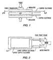
- Figures 1 and 2 shows the methods used to obtain the pressure and resistance measurements. A force transducer was used to measure the force applied to the copper electrodes. The apparent pressure was then calculated by dividing the electrode surface area into the measured force. The device resistance was measured using a four point probe micro ohmmeter. The comparative results presented in graphical form in Figure 3, were obtained using the same conductive polymer composition. That sample comprised a high density polyethylene/carbon black conductive polymer composition with copper electrodes.
- the surface of the unmodified conductive polymer composition was mechanically scribed with a cross-hatch pattern to increase the surface area and to improve the adhesion of the sputtered electrodes.
- Figure 4 shows the surface pattern developed in the surface of the conductive polymer composition by scribing. The surface was then scraped to remove loose debris, and was gently wiped with ethyl alcohol and lint free wipes. The scribed area was then framed with kapton tape to make a clean edge. The unmodified element was then sandwiched between two copper electrodes and the device resistance was measured at increasing pressures. The results are shown in Figure 3.
- the surface of the modified conductive polymer composition was prepared in the same way as the unmodified conductive polymer composition.
- the modified conductive polymer composition was subjected to further treatment, namely by plasma etching.
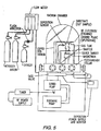
- the etching process was performed in a bell jar vacuum system like that depicted in Figure 5, for plasma processing. Using an oxygen/nitrogen plasma, the surface of the conductive polymer composition was etched.
- the process conditions implemented for the etching process are shown in Table 1.
Landscapes
- Engineering & Computer Science (AREA)
- Microelectronics & Electronic Packaging (AREA)
- Chemical & Material Sciences (AREA)
- Dispersion Chemistry (AREA)
- Ceramic Engineering (AREA)
- Physics & Mathematics (AREA)
- Electromagnetism (AREA)
- Manufacturing & Machinery (AREA)
- Thermistors And Varistors (AREA)
- Compositions Of Macromolecular Compounds (AREA)
Claims (6)
- Verfahren zum Herstellen einer PTC-Polymer-Strombegrenzungsvorrichtung, bei welchem eine leitende Polymerzusammensetzung, die ein Polymer mit darin dispergierten leitenden Teilchen enthält, hergestellt wird, mindestens zwei Oberflächen der Zusammensetzung mittels einer Plasmabearbeitungsprozedur behandelt wird, im Zuge deren die Oberflächen mittels Plasmaätzen mit den leitenden Teilchen angereichert werden und die Oberflächen mittels Plasmasputtern metallisiert werden, wobei die Plasmaätzprozedur vor der Plasmasputterprozedur erfolgt, und mindestens zwei Elektroden an den Oberflächen befestigt werden.
- Verfahren nach Anspruch 1, bei welchem die Elektroden an den behandelten Oberflächen mechanisch mittels Federdruck befestigt werden, indem ein elektrisch leitender Klebstoff benutzt wird, oder mittels Lötens oder Schweißens der metallisierten Oberflächen an diese.
- Verfahren nach Anspruch 1 oder 2, bei welchem das Plasmasputtern mit Teilchen von Tantal, Wolfram, Titan, Chrom, Molybdän, Vanadium, Zirconium, Aluminium, Silber, Nickel oder Gemischen daraus durchgeführt wird.
- Verfahren nach Anspruch 3, bei welchem die Teilchen ein Gemisch aus Wolfram und Titan sind.
- Verfahren nach einem der vorhergehenden Ansprüche, bei welchem die Vorrichtung eingeritzt wird, bevor sie der Plasmabearbeitungsprozedur unterworfen wird.
- PTC-Polymer-Strombegrenzungsvorrichtung, wie sie durch ein Verfahren nach einem der vorhergehenden Ansprüche erhalten werden kann.
Applications Claiming Priority (2)
| Application Number | Priority Date | Filing Date | Title |
|---|---|---|---|
| US770746 | 1996-12-19 | ||
| US08/770,746 US5841111A (en) | 1996-12-19 | 1996-12-19 | Low resistance electrical interface for current limiting polymers by plasma processing |
Publications (2)
| Publication Number | Publication Date |
|---|---|
| EP0853322A1 EP0853322A1 (de) | 1998-07-15 |
| EP0853322B1 true EP0853322B1 (de) | 2003-10-22 |
Family
ID=25089556
Family Applications (1)
| Application Number | Title | Priority Date | Filing Date |
|---|---|---|---|
| EP97309495A Expired - Lifetime EP0853322B1 (de) | 1996-12-19 | 1997-11-25 | Elektrischer Übergang mit niedrigem Widerstand in strombegrenzenden Polymeren, erzielt durch Plasmaverfahren |
Country Status (6)
| Country | Link |
|---|---|
| US (3) | US5841111A (de) |
| EP (1) | EP0853322B1 (de) |
| JP (1) | JPH10199706A (de) |
| CN (1) | CN1133179C (de) |
| CA (1) | CA2225212A1 (de) |
| DE (1) | DE69725692T2 (de) |
Cited By (1)
| Publication number | Priority date | Publication date | Assignee | Title |
|---|---|---|---|---|
| US7804392B2 (en) | 2005-02-17 | 2010-09-28 | Siemens Ag | Switching resistor for an electric switching device |
Families Citing this family (49)
| Publication number | Priority date | Publication date | Assignee | Title |
|---|---|---|---|---|
| US6812624B1 (en) | 1999-07-20 | 2004-11-02 | Sri International | Electroactive polymers |
| AU7291398A (en) | 1997-05-06 | 1998-11-27 | Thermoceramix, L.L.C. | Deposited resistive coatings |
| US6265051B1 (en) * | 1998-11-20 | 2001-07-24 | 3Com Corporation | Edge connectors for printed circuit boards comprising conductive ink |
| US6838972B1 (en) | 1999-02-22 | 2005-01-04 | Littelfuse, Inc. | PTC circuit protection devices |
| US6222166B1 (en) * | 1999-08-09 | 2001-04-24 | Watlow Electric Manufacturing Co. | Aluminum substrate thick film heater |
| US6320129B1 (en) * | 1999-09-21 | 2001-11-20 | Industrial Technology Research Institute | Method for making electrode of polymer composite |
| US6459358B1 (en) | 1999-09-27 | 2002-10-01 | Eaton Corporation | Flexible moldable conductive current-limiting materials |
| US6624383B1 (en) * | 2000-08-30 | 2003-09-23 | Parker-Hannifin Corporation | Using laser etching to improve surface contact resistance of conductive fiber filler polymer composites |
| EP1213728A3 (de) * | 2000-11-27 | 2005-10-26 | Eaton Corporation | Strombegrenzungseinrichtung |
| CA2429983A1 (en) | 2000-11-29 | 2002-08-01 | Thermoceramix, Inc. | Resistive heaters and uses thereof |
| US6597551B2 (en) | 2000-12-13 | 2003-07-22 | Huladyne Corporation | Polymer current limiting device and method of manufacture |
| EP1231613A1 (de) * | 2001-02-08 | 2002-08-14 | Abb Research Ltd. | Widerstandselemente mit PTC-Verhalten |
| JP2002313604A (ja) * | 2001-04-18 | 2002-10-25 | Tdk Corp | ポリマーptc素子 |
| TW529846U (en) * | 2001-11-12 | 2003-04-21 | Polytronics Technology Corp | Over-current protection component and the device |
| DK1512215T3 (da) * | 2002-03-18 | 2011-12-05 | Stanford Res Inst Int | Elektroaktive polymeranordning til bevægelse af fluid |
| US20040222406A1 (en) * | 2003-05-08 | 2004-11-11 | Fuzetec Technology Co., Ltd. | Positive temperature coefficient polymer composition and resettable fuse made therefrom |
| US6991003B2 (en) * | 2003-07-28 | 2006-01-31 | M.Braun, Inc. | System and method for automatically purifying solvents |
| CN1993778B (zh) * | 2004-06-08 | 2011-01-26 | 泰科电子雷伊化学株式会社 | 聚合物ptc元件 |
| US7544311B2 (en) * | 2005-04-06 | 2009-06-09 | Fuzetec Technology Co., Ltd. | Positive temperature coefficient polymer composition and circuit protection device made therefrom |
| WO2006123571A1 (ja) * | 2005-05-16 | 2006-11-23 | Tyco Electronics Raychem K.K. | 封口体およびそれを用いた電池パック |
| US8164415B2 (en) * | 2005-11-07 | 2012-04-24 | Tyco Electronics Japan G.K. | PTC device |
| JP5274019B2 (ja) * | 2005-12-09 | 2013-08-28 | タイコエレクトロニクスジャパン合同会社 | Ptcデバイスの製造方法 |
| EP2081413A1 (de) * | 2006-06-16 | 2009-07-22 | David Sanchez Duque | Heizplatte und verfahren zu ihrer herstellung |
| WO2008040700A1 (en) * | 2006-10-02 | 2008-04-10 | Arcelik Anonim Sirketi | A coating method and the coating formed thereby |
| SE530660C2 (sv) * | 2006-10-17 | 2008-08-05 | Conflux Ab | Värmeelement |
| US8728354B2 (en) * | 2006-11-20 | 2014-05-20 | Sabic Innovative Plastics Ip B.V. | Electrically conducting compositions |
| EP2174360A4 (de) | 2007-06-29 | 2013-12-11 | Artificial Muscle Inc | Wandler mit elektroaktivem polymer für anwendungen der sensorischen rückmeldung |
| US8003016B2 (en) * | 2007-09-28 | 2011-08-23 | Sabic Innovative Plastics Ip B.V. | Thermoplastic composition with improved positive temperature coefficient behavior and method for making thereof |
| EP2307807A2 (de) * | 2008-05-01 | 2011-04-13 | Thermoceramix, Inc. | Heizelementbeschichtungen verwendende kochgeräte |
| GB0815724D0 (en) * | 2008-08-29 | 2008-10-08 | Peratech Ltd | Pressure sensitive composition |
| US8063730B2 (en) * | 2008-09-30 | 2011-11-22 | Tsinghua University | Thermistor and electrical device employed with same |
| EP2239793A1 (de) | 2009-04-11 | 2010-10-13 | Bayer MaterialScience AG | Elektrisch schaltbarer Polymerfilmaufbau und dessen Verwendung |
| WO2012118916A2 (en) | 2011-03-01 | 2012-09-07 | Bayer Materialscience Ag | Automated manufacturing processes for producing deformable polymer devices and films |
| CN103703404A (zh) | 2011-03-22 | 2014-04-02 | 拜耳知识产权有限责任公司 | 电活化聚合物致动器双凸透镜系统 |
| WO2013105161A1 (ja) * | 2012-01-11 | 2013-07-18 | パナソニック株式会社 | 圧接型半導体装置及びその製造方法 |
| EP2828901B1 (de) | 2012-03-21 | 2017-01-04 | Parker Hannifin Corporation | Rolle-an-rolle-herstellungsverfahren zur herstellung selbstheilender elektroaktiver polymervorrichtungen |
| US9761790B2 (en) | 2012-06-18 | 2017-09-12 | Parker-Hannifin Corporation | Stretch frame for stretching process |
| CN103517467B (zh) * | 2012-06-27 | 2016-03-09 | 比亚迪股份有限公司 | 一种ptc电热元件、电加热装置以及电动车 |
| US9590193B2 (en) | 2012-10-24 | 2017-03-07 | Parker-Hannifin Corporation | Polymer diode |
| DE102014110560A1 (de) | 2014-07-25 | 2016-01-28 | Epcos Ag | Sensorelement, Sensoranordnung und Verfahren zur Herstellung eines Sensorelements und einer Sensoranordnung |
| DE102014110553A1 (de) * | 2014-07-25 | 2016-01-28 | Epcos Ag | Sensorelement, Sensoranordnung und Verfahren zur Herstellung eines Sensorelements |
| CN108290241A (zh) * | 2015-10-27 | 2018-07-17 | 哈钦森技术股份有限公司 | 将用于联接结构的聚合物、陶瓷和复合材料金属化 |
| CA3011250A1 (en) | 2016-01-12 | 2017-07-20 | 3M Innovative Properties Company | Heating tape and system |
| US10625083B2 (en) | 2016-06-27 | 2020-04-21 | Hutchinson Technology Incorporated | Metallized components and surgical instruments |
| US10925663B2 (en) | 2016-06-27 | 2021-02-23 | Mound Laser & Photonics Center, Inc. | Metallized components and surgical instruments |
| CN107622851B (zh) * | 2017-09-25 | 2019-06-18 | 江苏时恒电子科技有限公司 | 一种具有纳米颗粒膜的负温度系数热敏电阻及其制备方法 |
| CN107863212A (zh) * | 2017-09-25 | 2018-03-30 | 江苏时瑞电子科技有限公司 | 一种热敏电阻等离子喷涂贱金属铜双电极及其制备方法 |
| US12243978B2 (en) | 2019-06-28 | 2025-03-04 | Blue Current, Inc. | Thermally responsive solid state composite electrolyte separator |
| US11037708B2 (en) * | 2019-07-01 | 2021-06-15 | Littelfuse, Inc. | PPTC device having resistive component |
Family Cites Families (39)
| Publication number | Priority date | Publication date | Assignee | Title |
|---|---|---|---|---|
| US3351882A (en) * | 1964-10-09 | 1967-11-07 | Polyelectric Corp | Plastic resistance elements and methods for making same |
| US3858144A (en) * | 1972-12-29 | 1974-12-31 | Raychem Corp | Voltage stress-resistant conductive articles |
| US3835434A (en) * | 1973-06-04 | 1974-09-10 | Sprague Electric Co | Ptc resistor package |
| US4330703A (en) * | 1975-08-04 | 1982-05-18 | Raychem Corporation | Layered self-regulating heating article |
| US4775778A (en) * | 1976-10-15 | 1988-10-04 | Raychem Corporation | PTC compositions and devices comprising them |
| US4304987A (en) * | 1978-09-18 | 1981-12-08 | Raychem Corporation | Electrical devices comprising conductive polymer compositions |
| US4315237A (en) * | 1978-12-01 | 1982-02-09 | Raychem Corporation | PTC Devices comprising oxygen barrier layers |
| US4238812A (en) * | 1978-12-01 | 1980-12-09 | Raychem Corporation | Circuit protection devices comprising PTC elements |
| NZ193661A (en) * | 1979-05-10 | 1983-06-17 | Sunbeam Corp | Heating element conductive and ptc material |
| US4272471A (en) * | 1979-05-21 | 1981-06-09 | Raychem Corporation | Method for forming laminates comprising an electrode and a conductive polymer layer |
| DE2930350C2 (de) * | 1979-07-26 | 1981-04-02 | Gewerkschaft Schalker Eisenhütte, 4650 Gelsenkirchen | Reinigungseinrichtung zum Reinigen der Türrahmen bzw. Reinigungseinrichtung zum Reinigen der Türen von Verkokungskammern eines Verkokungsofens |
| US5049850A (en) * | 1980-04-21 | 1991-09-17 | Raychem Corporation | Electrically conductive device having improved properties under electrical stress |
| US4317027A (en) * | 1980-04-21 | 1982-02-23 | Raychem Corporation | Circuit protection devices |
| US4545926A (en) * | 1980-04-21 | 1985-10-08 | Raychem Corporation | Conductive polymer compositions and devices |
| US4475138A (en) * | 1980-04-21 | 1984-10-02 | Raychem Corporation | Circuit protection devices comprising PTC element |
| US4314231A (en) * | 1980-04-21 | 1982-02-02 | Raychem Corporation | Conductive polymer electrical devices |
| US4314230A (en) * | 1980-07-31 | 1982-02-02 | Raychem Corporation | Devices comprising conductive polymers |
| US4426633A (en) * | 1981-04-15 | 1984-01-17 | Raychem Corporation | Devices containing PTC conductive polymer compositions |
| US4845838A (en) * | 1981-04-02 | 1989-07-11 | Raychem Corporation | Method of making a PTC conductive polymer electrical device |
| US5195013A (en) * | 1981-04-02 | 1993-03-16 | Raychem Corporation | PTC conductive polymer compositions |
| US4485838A (en) * | 1983-02-24 | 1984-12-04 | Toray Industries, Inc. | Methods for manufacturing lead fiber and radiation shielding material using the same |
| US4780598A (en) * | 1984-07-10 | 1988-10-25 | Raychem Corporation | Composite circuit protection devices |
| US4857880A (en) * | 1985-03-14 | 1989-08-15 | Raychem Corporation | Electrical devices comprising cross-linked conductive polymers |
| US4685025A (en) * | 1985-03-14 | 1987-08-04 | Raychem Corporation | Conductive polymer circuit protection devices having improved electrodes |
| US4724417A (en) * | 1985-03-14 | 1988-02-09 | Raychem Corporation | Electrical devices comprising cross-linked conductive polymers |
| US4774024A (en) * | 1985-03-14 | 1988-09-27 | Raychem Corporation | Conductive polymer compositions |
| US4647894A (en) * | 1985-03-14 | 1987-03-03 | Raychem Corporation | Novel designs for packaging circuit protection devices |
| US4689475A (en) * | 1985-10-15 | 1987-08-25 | Raychem Corporation | Electrical devices containing conductive polymers |
| JPS63312601A (ja) * | 1987-06-15 | 1988-12-21 | Tdk Corp | 導電性重合体ptc抵抗素子及びその製造方法 |
| US4907340A (en) * | 1987-09-30 | 1990-03-13 | Raychem Corporation | Electrical device comprising conductive polymers |
| US4924074A (en) * | 1987-09-30 | 1990-05-08 | Raychem Corporation | Electrical device comprising conductive polymers |
| JPH0826462B2 (ja) * | 1987-11-30 | 1996-03-13 | 龍徳 四十宮 | 表面金属化重合体成形物の製造方法 |
| US4910389A (en) * | 1988-06-03 | 1990-03-20 | Raychem Corporation | Conductive polymer compositions |
| EP0404959B1 (de) * | 1988-09-24 | 1995-05-10 | Dai Nippon Insatsu Kabushiki Kaisha | Elektrisch-leitendes Thermo-transfer Band |
| JPH047801A (ja) * | 1990-04-25 | 1992-01-13 | Daito Tsushinki Kk | Ptc素子 |
| US5436609A (en) * | 1990-09-28 | 1995-07-25 | Raychem Corporation | Electrical device |
| US5281845A (en) * | 1991-04-30 | 1994-01-25 | Gte Control Devices Incorporated | PTCR device |
| JPH0521208A (ja) * | 1991-05-07 | 1993-01-29 | Daito Tsushinki Kk | Ptc素子 |
| EP0640995B1 (de) * | 1993-08-25 | 1997-06-25 | Abb Research Ltd. | Elektrisches Widerstandselement und Verwendung dieses Widerstandselementes in einem Strombegrenzer |
-
1996
- 1996-12-19 US US08/770,746 patent/US5841111A/en not_active Expired - Fee Related
-
1997
- 1997-03-12 US US08/820,398 patent/US5928547A/en not_active Expired - Fee Related
- 1997-05-05 US US08/850,465 patent/US5886324A/en not_active Expired - Fee Related
- 1997-11-25 EP EP97309495A patent/EP0853322B1/de not_active Expired - Lifetime
- 1997-11-25 DE DE69725692T patent/DE69725692T2/de not_active Expired - Fee Related
- 1997-12-18 JP JP9365067A patent/JPH10199706A/ja not_active Withdrawn
- 1997-12-18 CA CA002225212A patent/CA2225212A1/en not_active Abandoned
- 1997-12-18 CN CN97108729A patent/CN1133179C/zh not_active Expired - Fee Related
Cited By (1)
| Publication number | Priority date | Publication date | Assignee | Title |
|---|---|---|---|---|
| US7804392B2 (en) | 2005-02-17 | 2010-09-28 | Siemens Ag | Switching resistor for an electric switching device |
Also Published As
| Publication number | Publication date |
|---|---|
| CN1133179C (zh) | 2003-12-31 |
| CA2225212A1 (en) | 1998-06-19 |
| US5928547A (en) | 1999-07-27 |
| DE69725692T2 (de) | 2004-07-22 |
| US5841111A (en) | 1998-11-24 |
| EP0853322A1 (de) | 1998-07-15 |
| DE69725692D1 (de) | 2003-11-27 |
| CN1185635A (zh) | 1998-06-24 |
| US5886324A (en) | 1999-03-23 |
| JPH10199706A (ja) | 1998-07-31 |
Similar Documents
| Publication | Publication Date | Title |
|---|---|---|
| EP0853322B1 (de) | Elektrischer Übergang mit niedrigem Widerstand in strombegrenzenden Polymeren, erzielt durch Plasmaverfahren | |
| JP5711365B2 (ja) | 正温度係数抵抗を有する導電性複合材料及び過電流保護素子 | |
| KR960011153B1 (ko) | 도전성 중합체를 포함하고 있는 전기장치 | |
| EP0908902B1 (de) | PTC-Element, Schutzvorrichtung und elektrische Leiterplatte | |
| KR100295013B1 (ko) | 유기질ptc더어미스터및이것을이용한형광램프과열방지장치 | |
| EP0815568B1 (de) | Elektrische vorrichtung | |
| JP4666760B2 (ja) | 導電性ポリマーを用いた電気デバイス | |
| US6074576A (en) | Conductive polymer materials for high voltage PTC devices | |
| EP0764333A1 (de) | Leitfähige polymere enthaltende elektrische vorrichtungen | |
| WO2001009905A2 (en) | Electrically conductive polymer composition | |
| CA2479926A1 (en) | Ptc conductive composition containing a low molecular weight polyethylene processing aid | |
| US5817423A (en) | PTC element and process for producing the same | |
| US6660795B2 (en) | PTC conductive polymer compositions | |
| US6359544B1 (en) | Conductive polymer compositions containing surface treated kaolin clay and devices | |
| US6197220B1 (en) | Conductive polymer compositions containing fibrillated fibers and devices | |
| US20020161090A1 (en) | PTC conductive polymer compositions | |
| JP3168262B2 (ja) | 回路保護装置 | |
| WO2001006521A1 (fr) | Dispositif a coefficient de temperature positif et son procede de fabrication | |
| KR20000075344A (ko) | 피.티.시. 저항소자 제조용 수지 조성물 | |
| KR0183371B1 (ko) | 정온도 계수 소자 | |
| JP2004193626A (ja) | Ptc回路保護装置 | |
| CA2292935A1 (en) | Current limiting device with reduced resistance | |
| CN1917101A (zh) | 过电流保护元件 | |
| JPH076864A (ja) | 正抵抗温度係数発熱体およびその製造方法 |
Legal Events
| Date | Code | Title | Description |
|---|---|---|---|
| PUAI | Public reference made under article 153(3) epc to a published international application that has entered the european phase |
Free format text: ORIGINAL CODE: 0009012 |
|
| AK | Designated contracting states |
Kind code of ref document: A1 Designated state(s): DE FR IT |
|
| AX | Request for extension of the european patent |
Free format text: AL;LT;LV;MK;RO;SI |
|
| 17P | Request for examination filed |
Effective date: 19980928 |
|
| AKX | Designation fees paid |
Free format text: DE FR IT |
|
| RBV | Designated contracting states (corrected) |
Designated state(s): DE FR IT |
|
| 17Q | First examination report despatched |
Effective date: 20020130 |
|
| GRAH | Despatch of communication of intention to grant a patent |
Free format text: ORIGINAL CODE: EPIDOS IGRA |
|
| GRAS | Grant fee paid |
Free format text: ORIGINAL CODE: EPIDOSNIGR3 |
|
| GRAA | (expected) grant |
Free format text: ORIGINAL CODE: 0009210 |
|
| AK | Designated contracting states |
Kind code of ref document: B1 Designated state(s): DE FR IT |
|
| PGFP | Annual fee paid to national office [announced via postgrant information from national office to epo] |
Ref country code: FR Payment date: 20031105 Year of fee payment: 7 |
|
| REF | Corresponds to: |
Ref document number: 69725692 Country of ref document: DE Date of ref document: 20031127 Kind code of ref document: P |
|
| PGFP | Annual fee paid to national office [announced via postgrant information from national office to epo] |
Ref country code: DE Payment date: 20031128 Year of fee payment: 7 |
|
| ET | Fr: translation filed | ||
| PLBE | No opposition filed within time limit |
Free format text: ORIGINAL CODE: 0009261 |
|
| STAA | Information on the status of an ep patent application or granted ep patent |
Free format text: STATUS: NO OPPOSITION FILED WITHIN TIME LIMIT |
|
| 26N | No opposition filed |
Effective date: 20040723 |
|
| PG25 | Lapsed in a contracting state [announced via postgrant information from national office to epo] |
Ref country code: DE Free format text: LAPSE BECAUSE OF NON-PAYMENT OF DUE FEES Effective date: 20050601 |
|
| PG25 | Lapsed in a contracting state [announced via postgrant information from national office to epo] |
Ref country code: FR Free format text: LAPSE BECAUSE OF NON-PAYMENT OF DUE FEES Effective date: 20050729 |
|
| REG | Reference to a national code |
Ref country code: FR Ref legal event code: ST |
|
| PG25 | Lapsed in a contracting state [announced via postgrant information from national office to epo] |
Ref country code: IT Free format text: LAPSE BECAUSE OF NON-PAYMENT OF DUE FEES;WARNING: LAPSES OF ITALIAN PATENTS WITH EFFECTIVE DATE BEFORE 2007 MAY HAVE OCCURRED AT ANY TIME BEFORE 2007. THE CORRECT EFFECTIVE DATE MAY BE DIFFERENT FROM THE ONE RECORDED. Effective date: 20051125 |