EP0852430A2 - Anfangssynchronisation für ein Direktsequenz CDMA Zellularsystem - Google Patents
Anfangssynchronisation für ein Direktsequenz CDMA Zellularsystem Download PDFInfo
- Publication number
- EP0852430A2 EP0852430A2 EP19980100081 EP98100081A EP0852430A2 EP 0852430 A2 EP0852430 A2 EP 0852430A2 EP 19980100081 EP19980100081 EP 19980100081 EP 98100081 A EP98100081 A EP 98100081A EP 0852430 A2 EP0852430 A2 EP 0852430A2
- Authority
- EP
- European Patent Office
- Prior art keywords
- code
- synthesized
- output
- spread code
- long
- Prior art date
- Legal status (The legal status is an assumption and is not a legal conclusion. Google has not performed a legal analysis and makes no representation as to the accuracy of the status listed.)
- Withdrawn
Links
Images


Classifications
-
- H—ELECTRICITY
- H04—ELECTRIC COMMUNICATION TECHNIQUE
- H04B—TRANSMISSION
- H04B1/00—Details of transmission systems, not covered by a single one of groups H04B3/00 - H04B13/00; Details of transmission systems not characterised by the medium used for transmission
- H04B1/69—Spread spectrum techniques
- H04B1/707—Spread spectrum techniques using direct sequence modulation
- H04B1/7073—Synchronisation aspects
- H04B1/7075—Synchronisation aspects with code phase acquisition
- H04B1/7077—Multi-step acquisition, e.g. multi-dwell, coarse-fine or validation
-
- H—ELECTRICITY
- H04—ELECTRIC COMMUNICATION TECHNIQUE
- H04B—TRANSMISSION
- H04B1/00—Details of transmission systems, not covered by a single one of groups H04B3/00 - H04B13/00; Details of transmission systems not characterised by the medium used for transmission
- H04B1/69—Spread spectrum techniques
- H04B1/707—Spread spectrum techniques using direct sequence modulation
- H04B1/7073—Synchronisation aspects
- H04B1/7075—Synchronisation aspects with code phase acquisition
- H04B1/70755—Setting of lock conditions, e.g. threshold
-
- H—ELECTRICITY
- H04—ELECTRIC COMMUNICATION TECHNIQUE
- H04B—TRANSMISSION
- H04B1/00—Details of transmission systems, not covered by a single one of groups H04B3/00 - H04B13/00; Details of transmission systems not characterised by the medium used for transmission
- H04B1/69—Spread spectrum techniques
- H04B1/707—Spread spectrum techniques using direct sequence modulation
- H04B1/7073—Synchronisation aspects
- H04B1/7083—Cell search, e.g. using a three-step approach
-
- H—ELECTRICITY
- H04—ELECTRIC COMMUNICATION TECHNIQUE
- H04B—TRANSMISSION
- H04B1/00—Details of transmission systems, not covered by a single one of groups H04B3/00 - H04B13/00; Details of transmission systems not characterised by the medium used for transmission
- H04B1/69—Spread spectrum techniques
- H04B1/707—Spread spectrum techniques using direct sequence modulation
- H04B1/709—Correlator structure
-
- H—ELECTRICITY
- H04—ELECTRIC COMMUNICATION TECHNIQUE
- H04B—TRANSMISSION
- H04B1/00—Details of transmission systems, not covered by a single one of groups H04B3/00 - H04B13/00; Details of transmission systems not characterised by the medium used for transmission
- H04B1/69—Spread spectrum techniques
- H04B1/707—Spread spectrum techniques using direct sequence modulation
- H04B1/7073—Synchronisation aspects
- H04B1/70735—Code identification
-
- H—ELECTRICITY
- H04—ELECTRIC COMMUNICATION TECHNIQUE
- H04B—TRANSMISSION
- H04B1/00—Details of transmission systems, not covered by a single one of groups H04B3/00 - H04B13/00; Details of transmission systems not characterised by the medium used for transmission
- H04B1/69—Spread spectrum techniques
- H04B1/707—Spread spectrum techniques using direct sequence modulation
- H04B1/7073—Synchronisation aspects
- H04B1/7075—Synchronisation aspects with code phase acquisition
- H04B1/70751—Synchronisation aspects with code phase acquisition using partial detection
-
- H—ELECTRICITY
- H04—ELECTRIC COMMUNICATION TECHNIQUE
- H04B—TRANSMISSION
- H04B2201/00—Indexing scheme relating to details of transmission systems not covered by a single group of H04B3/00 - H04B13/00
- H04B2201/69—Orthogonal indexing scheme relating to spread spectrum techniques in general
- H04B2201/707—Orthogonal indexing scheme relating to spread spectrum techniques in general relating to direct sequence modulation
- H04B2201/70702—Intercell-related aspects
Definitions
- the present invention relates to an initial synchronization method and a receiver for initial synchronization in a DS-CDMA (Direct Sequence-Code Division Multiple Access) inter base station asynchronous cellular system.
- DS-CDMA Direct Sequence-Code Division Multiple Access
- CDMA code division multiple access
- SS spread spectrum
- cellular systems require two kinds of cell searches, namely, an initial cell search by which an initial cell to be connected to a mobile station is identified, and a neighboring cell search by which neighboring cells are searched for the hand-over.
- an initial cell search by which an initial cell to be connected to a mobile station is identified
- a neighboring cell search by which neighboring cells are searched for the hand-over.
- each of the cells uses the same frequency.
- the initial synchronization needs to reduce the timing error between the spread code of the received signal and the spread code replica generated by the receiver to within 1 ⁇ 2 chip period while the simultaneous cell search.
- DS-CDMA cellular systems can be categorized into two classes, namely, inter base station synchronous systems in which temporal synchronization is performed strictly among all base stations, and inter base station asynchronous systems in which temporal synchronization is not performed.
- Inter base station synchronous systems achieve inter base station synchronization using other systems such as the GPS (Global Positioning System) . Since each of the base stations uses the same long code by giving it a delay which differs from one base station to another, it suffices to synchronize only the timing of the long code during the initial search.
- the neighboring cell search for the hand-over can be performed at a higher speed since the mobile station receives the code delay information of the neighboring base stations directly from the given base station with which the mobile station is at a given time communicating.
- each of the base stations uses a different spread code in order to identify the base stations.
- the mobile station needs to identify the spread codes in performing the initial cell search.
- the number of codes to be searched can be limited by obtaining the spread codes of the neighboring base stations from the current base station to which the mobile station belongs.
- the search time is longer. Indeed when a long code is used for the spread code, the amount of time for the cell search becomes enormous.
- this inter base station asynchronous system has an advantage in that other systems such as GPS are not needed.
- a cell search system capable of solving these problems inherent in the inter base station asynchronous systems and performing initial synchronization at a high speed is being proposed by Kenichi Higuchi, Mamoru Sawahashi, and Fumiyuki Adachi, in " Two-step high speed long code initial synchronization method in the DS-CDMA inter base station asynchronous system " (Shingakugihou CS-96-19, RCS96-12 (1996-05)) .
- this initial synchronization method a spread code sequence synthesized from a long code corresponding to the cells and a short code corresponding to a communication channel is used to doubly spread the data.
- a second short code common to all cells is assigned to the control channel in order to perform the initial synchronization in two steps.
- a matched filter de-spreads the received signal by using the short code and detects the timing of the long code.
- a correlator identifies the long code corresponding to a cell by using a spread code sequence synthesized from the long code corresponding to the cell and the specific short code.
- Fig. 1 illustrates a configuration of cells.
- the numeral 61 represents the mobile station.
- Each of the cells #1 through #n has one of the base stations BS 1 , BS 2 , , BSn, respectively.
- Each base station sends a signal to the mobile station 61 by using symbols which are doubly spread by the long codes #1, #2, , #n and the short codes #0 - #s identifying each channel.
- the short codes #0 - #s are common to each of the cells.
- the common short code #0 is assigned to the control channel of each of the cells.
- Fig. 2 is a timing chart for explaining the conventional two-step high speed initial synchronization method, and an example of a signal of a control channel received at a mobile station.
- the control channel received from each of the base stations contains certain symbols, which have been spread only by the short code #0 every long-code period. Signals received from BS k-2 , BS k-1 , and BS k are shown in the drawing and the certain symbols are shown as shaded portions of the signals.
- This short code #0 is assigned commonly to all of the base stations, and this is achieved by not spreading the signals with the long codes over a certain period.
- the other symbol positions of the control channels are doubly spread using the long code #i, which differs from one base station to another, and the short code #0. In this way, the control channels transmitted from each of the base stations BS k-2 - BS k are asynchronously multiplexed and are received at the mobile station.
- the mobile station finds a correlation between the base band received signal and the short code #0 using a matched filter.
- the peak of the correlation is detected at the temporal position corresponding to the reception timing of the symbol which is spread with the short code #0 of the control channel of the base stations.
- the timing corresponding to the maximum electric power is detected after these peak electric powers have been detected over the R-period of the long code.
- the detected timing, the code timing T is determined to be the long code synchronization timing transmitted from the base station of the new cell in which a mobile station is located.
- the mobile station 61 In the second stage, in order to identify the base station BS k , the mobile station 61 identifies the long code #k that is used to spread the control channel, the long code timing T of which has been detected. In order to accomplish this, the long code #k is sequentially selected out of the long codes #1 - #n of the system in the initial cell search. A replica code is synthesized from the selected long code #k and the short code #0, and correlation is detected by a correlator using the long code synchronization timing obtained in the first stage.
- the correlation detection is continued over the range of long codes #1 - #n until a long code causes the correlation detection value to exceed the threshold value.
- the long code that has exceeded the threshold value is judged to be the long code #k of the new base station, and the cell search is completed.
- a replica code is synthesized from the short code #0 and the long code #k.
- the long code #k is sequentially selected from the long codes of neighboring cells transmitted by the current base station to the mobile station. Correlation is detected using the long code synchronization timing.
- cell search can be performed at a high speed by performing the timing synchronization and the identification of the long code separately.
- correlation detection needs to be performed approximately (the number of spread codes ⁇ the number of phases of the spread codes) times to search a cell.
- spread code sequences are made of long codes corresponding to the cells and short codes corresponding to the communication channels.
- a specific short code common to each of the cells is assigned to the control channel for the initial synchronization of the DS-CDMA inter base station asynchronous cellular system.
- the long code synchronization timing transmitted from the corresponding base station is determined.
- a synthesized code for each long code is defined by a combination of the long code and the specific short code.
- the matched filter detects the correlation between the received signal and each of several segments, each segment being taken from a portion of one of the synthesized code.
- the segment taken from a next synthesized code is extracted starting from a position in the next synthesized code, which is shifted by a predetermined amount from where the segment of the first synthesized code was extracted. The amount of shifting, however, is smaller than the length of the segments.
- the long code transmitted from the corresponding base station is identified based on the magnitude of the electric power of the correlation.
- the correlation between each of the segments and the received signal is detected based on the long code synchronization timing, by sequentially replacing each of the segments every time, an interval of the received signal corresponding to the prescribed chip number is newly input to the matched filter.
- a portion of the base band received signal still remains in the matched filter at the time the correlation with the segment of one synthesized code has been processed.
- the portion can be used for processing the correlation with the segment of the next synthesized code instead of being disposed of. Consequently, the long codes can be searched at a higher speed.
- the received signal used for the previous correlation is discarded immediately before processing the next correlation.
- the receiver for the DS-CDMA inter base station asynchronous cellular system uses spread code sequences synthesized from long codes corresponding to the cells and short codes corresponding to the communication channels.
- a specific short code is assigned to the control channel of all cells.
- the receiver has a spread code generating means for outputting each of several segments, each segment being taken from a portion of one of the synthesized code.
- the segment taken from a next synthesized code is extracted starting from a position in the next synthesized code, which is shifted by a predetermined amount from where the segment of the first synthesized code was extracted.
- the amount of shifting is smaller than the length of the segments.
- a matched filter finds a correlation between the output of the corresponding spread code generating means and the received signal.
- a long code synchronization timing determination means determines the long code synchronization timing transmitted from the corresponding base station using the correlation between the specific short code and the received signal.
- the long code identification means supplies one of the segments to the matched filter from the spread code generating means based on the long code synchronization timing. Then the long code identification means sequentially replaces each of the segments and supplies the segment every time an interval of the received signal corresponding to the amount of shifting is newly input to the matched filter, and identifies the long codes transmitted from the corresponding base station based on the magnitude of the electric power of the output signal of the matched filter. Accordingly, long codes can be searched faster.
- the spread code generating means further outputs the specific short code.
- the long code synchronization timing determination means supplies the specific short code from the spread code generating means to the matched filter, and determines the synchronization timing of the long code transmitted from the corresponding base station based on the electric power of the output signal of the matched filter. Therefore, the long code synchronization timing can be easily determined.
- the long code synchronization timing and the identification of the long code can be determined using the matched filter.
- the matched filter has multiple sample holders and multiple multipliers for outputting signals from the sample holders as the first and second outputs according to the value of the bits corresponding to the output of the spread code generating means.
- a first analog addition circuit adds the first outputs of the multipliers.
- a second analog addition circuit adds the second outputs of the multipliers.
- a third analog addition circuit subtracts the output of the first analog addition circuit from the output of the second analog addition circuit. Since the above-mentioned matched filter consumes a small amount of electric power, the electric power consumption of the receiver can be reduced accordingly.
- Fig. 1 shows a conventional structure of the cells of DS-CDMA communication system.
- Fig. 2 is a timing chart of the conventional two-step high speed initial synchronization method.
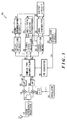
- Fig. 3 is a block diagram of the signal reception circuit of the mobile station 61 shown in Fig. 1.
- Fig. 4 is a block diagram of the long code search circuit shown in Fig. 3.
- Fig. 5 is a block diagram of the matched filter 18.
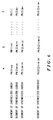
- Fig. 6 shows a synthesized code to be input to the coefficient input terminal of the matched filter.
- Fig. 7 is a flowchart of the initial cell search of the embodiment shown in Fig. 4.
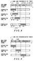
- Fig. 8 shows the relation between the base band received signal and the segments of the synthesized codes to be correlation-processed according to the embodiment of the present invention.
- Fig. 9 shows the relation between the base band received signal and the segments of the codes according to the prior art.
- Fig. 10 is a block diagram of an example of the matched filter in Fig. 1.
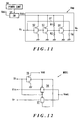
- Fig. 11 illustrates the inversion amplifier Amp.
- Fig. 12 illustrates the multiplier MUX.
- Fig. 13 illustrates the reference voltage generator Vref.
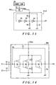
- Fig. 14 illustrates an analog operation circuit that supplies the input voltage to the inversion amplifier via capacitors.
- Each base station periodically masks the long code of one information symbol length every long code cycle which starts at a prescribed time of the control channel, and transmits the symbol that has been spread only by the short code #0 that is common to all base stations.
- the transmitter of the base station BS transmits a transmission signal obtained by spreading the transmission data with binary spread codes and QPSK-modulating the transmission signal.
- Fig. 3 is a block diagram of the signal reception circuit of the mobile station 61 shown in Fig. 1.
- a spectrum spread signal received by a reception antenna 11 is demodulated from the BPSK and transformed into an intermediate frequency signal by a high frequency receiver 12, split into two signals by a distributor 13, and supplied to multipliers 16 and 17.
- An oscillator 14 generates a signal ( cos ⁇ t ) having an intermediate frequency.
- the output from the oscillator 14 is directly supplied to the multiplier 16.
- the output from the oscillator 14 is also input to the multiplier 17 via a phase shift circuit 15 which shifts the phase of the output signal supplied from the oscillator 14 by ⁇ /2.
- the multiplier 16 multiplies the intermediate frequency signal received from the distributor 13 by the oscillation output received from the oscillator 14 and outputs a base band signal Ri which is an in-phase component (I component) and is output via a low-pass filter 62.
- the multiplier 17 multiplies the intermediate frequency signal received from the distributor 13 by the output ( sin ⁇ t ) of the phase shift circuit 15, and outputs a base band signal Rq which is a quadrature component (Q component). In this way, the received signal is quadrature-detected.
- the base band signals Ri and Rq are input to a complex-type matched filter 18, multiplied by a PN code sequence generated by a PN code sequence generator 19, and are de-spread.
- the in-phase component Si of the de-spread output and the quadrature component Sq of the de-spread output received from the complex-type matched filter 18 are input to a delay detection circuit 20, a signal level detector 22, and a phase correction means 24.
- the delay detection circuit 20 detects the delay of the de-spread output Si and Sq and outputs the detected delay to a frame synchronization circuit 21 which detects the timing of each frame.
- the resultant output timing signal Ct is input to a phase correction means 24.
- the signal level detector 22 calculates the electric power (correlation value) from the de-spread output Si which is the I component and the de-spread output Sq which is the Q component.
- the resultant output Lb from the signal level detector 22 is supplied to a multi-path selector 23 and a long code search circuit 27.
- the long code search circuit 27 searches the long code and supplies the number Lc of the long code to the PN generator 19.
- the multi-path selector 23 selects multiple peaks having high received signal levels from among the peaks of the signals received through multiple paths.
- the output Cm of the multi-path selection circuit 23 is input to the phase correction means 24.
- the phase correction means 24 corrects the phase of the signal received through each path.
- the Rake synthesizer 25 synthesizes, at a synchronized timing, the phase-corrected output of each path received from the phase correction means 24, and outputs the synthesized output to the output circuit 26.
- the output of the output circuit 26 is supplied to a subsequent decision circuit or the like not shown in the drawing, which de-modulates and processes the signal.
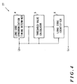
- Fig. 4 is a block diagram of the long code search circuit 27 shown in Fig. 3.
- the electric power Lb output from the signal level detector 22 is supplied to the long code synchronization timing determiner 4, the threshold value calculator 5, and the long code identifier 6.
- the PN generator 19 is controlled by the long code synchronization timing determiner 4 and the long code identifier 6. At the time of the initial search, the PN generator 19 outputs the short code #0 that is common to the control channels of all base stations. After the long code synchronization timing has been determined, each segment having N chips, which is a portion of the spread code sequence synthesized from the short code #0 and one of the long codes #i unique to each base station, is sequentially loaded and output.
- the short code #0 common to the control channels of all base stations is output.
- the long code search circuit 27 sequentially replaces and outputs each segment having N chips, which forms a portion of a code synthesized from the short code #0 and one of the long codes #i.
- the segment taken from a next synthesized code is extracted starting from a position in the next synthesized code which is shifted by a predetermined amount from where the segment of the first synthesized code was extracted.
- the amount of shifting is smaller than the length of the segments.
- the long code search circuit 27 searches the long code of the new base station based on the information of the long codes of the neighboring cells received from the control channel of the base station to which the mobile station currently belongs.
- the long code synchronization timing determiner 4 in the initial cell search,
- the threshold value calculator 5 calculates a threshold value to be output to the long code identifier 6 based on the electric power of the maximum correlation value of the long code identification timing. In the neighboring cell search before the hand-over,
- the long code identifier 6 sequentially supplies and replaces each of the segments after the long code identification timing is detected, and compares the output Lb of the signal level detector 22 with the prescribed threshold value. If the output Lb of the signal level detector 22 exceeds this threshold value, the synthesized code supplied to the matched filter is identified as the synthesized code of the new base station.
- Fig. 5 is a schematic drawing of the matched filter 18. In this drawing, it is assumed that the base band received signal is input with positive and negative polarities and that the segments of each synthesized code consists of a binary code sequence, which has values 1 and/or - 1.
- the complex-type matched filter 18 has a shift register 71 consisting of steps, the number of which equals a chip number associated with the amount of shifting between successive synthesized codes, a multiplier 72 for multiplying the tap output of each of the register steps and the coefficient inputs, and an adder 73 for adding all the outputs of the multiplier 72.
- a portion of the shift register 71 consists of, in practice, analog devices such as a CCD (Charge Coupled Device) and a SAW (Surface Acoustic Wave) filter, or digital devices such as digital IC circuits.
- a little electric matched filter having analog operation circuits can be used to save the power consumption.
- the complex-type matched filter 18 is operated only for the duration of time in which the peaks of the correlation value can be detected at prescribed time intervals. Even if a matched filter consumes a lot of electric power in the operation for the synchronization, the matched filter operates only at intervals and so the electric power consumption, as a whole, can be kept low.
- Fig. 6 shows segments of the synthesized codes to be input to the coefficient input terminals of the matched filter 18.
- the symbols A, B, , Z written above the code sequences indicate that respective codes are input to the coefficient input terminals A, B - Z, respectively, of Fig. 5.
- the symbol M represents a natural number.
- Fig. 7 is a flow chart for explaining the initial cell search operation.
- the PN generator 19 loads the short code #0 to the complex-type matched filter 18.
- a correlation between the base band received signal and the short code #0 is obtained by the complex-type matched filter 18.
- the signal level detector 22 detects the electric power of the output of the complex-type matched filter 18, and outputs the result to the long code synchronization timing determiner 4.
- the long code synchronization timing determiner 4 stores the values of this electric power, and their time within the period of the long code, when the electric power exceeds a certain threshold value.
- the threshold value can be adaptive-controlled corresponding to the base band received signal by determining the average level of the electric power that has been output from the signal level detector 22.
- the above-mentioned process is performed over multiple periods of the long code and the values and their time are stored for multiple times.
- the stored values of the corresponding time are averaged and are compared with those of the different time.
- the timing at which the electric power corresponding to the maximum correlation value is achieved is selected after the averaging operation has been completed.
- the selected timing is output to the PN generator 19 as the long code synchronization timing.
- the long code synchronization timing determiner 4 initially sets the value of i to 1.
- the PN generator 19 loads a segment having a prescribed chip length, for example, 128 chips, which forms a portion of a code synthesized from the long code #1 and the short code #0. As shown in Fig. 6, PN(1) 128 , PN(1) 127, , PN(1) 1 are initially input to the coefficient input terminals A - Z.
- the complex-type matched filter 18 finds a correlation between the base band received signal and the segment of the synthesized code #1, namely, a partial correlation with the synthesized code #1.
- the long code identifier 6 determines whether the electric power of the correlation output has exceeded the threshold value or not. Specifically, a correlation between the base band received signal and the segment of the synthesized code #1 is obtained. If the output of the signal level detector 22 is greater than the prescribed threshold value calculated by the threshold value calculator 5, then the process is advanced to S27. If the output of the signal level detector 22 is not greater than the prescribed threshold value calculated by the threshold value calculator 5, the process is advanced to S28.
- the threshold value calculator 5 can adaptively control the threshold value corresponding to the base band received signal by outputting an electric power level which represents a prescribed percentage of the electric power corresponding to the maximum correlation peak value at the time of the long code synchronization timing or the average level of the output electric power of the signal level detector 22 up to the present time.
- the long code #i obtained at this stage is determined to be the long code for the desired base station, and the cell search is finished.
- S28 it is determined whether the long code #i is the last long code or not. If the long code #i is the last long code, then the process is returned to S21, and the process is repeated beginning from the determination of the long code synchronization timing. If the long code #i is not the last long code, the process is advanced to S29.
- the last long code used in this DS-CDMA inter base station asynchronous cellular system is labeled as, for example, long code #512.
- the PN generator 19 loads a segment of the synthesized code #2 synthesized from the long code #2 and the short code #0 to the complex-type matched filter 18.
- this segment of the synthesized code #2 is a sequence PN(2) 128 , PN(2) 127 , , PN(2) 1 , as in the case of the synthesized code #1, and obtain a correlation with the base band received signal.
- the base band received signal is correlated with the segment of the next synthesized code #2, after the correlation between the base band received signal and the segment of the synthesized code #1 is obtain, and when the M chips of the base band received signal have been input. While the above procedure is being performed, the M chips of the base band received signal are newly being input to the shift register 71 shown in Fig. 5 and are being shifted.
- the segment of the next synthesized code #2 with which the correlation is obtained needs to be put in correspondence with the shift of the base band received signal.
- the segment is input to the coefficient input terminals A - Z shown in Fig. 5 as a sequence PN(2) M + 128 , PN(2) M + 127, , PN(2) M + 1 .
- the value of M may be set low in comparison with the chip number of the short code.
- Fig. 8 shows the correspondence between the base band received signal and the segment of each synthesized code to be correlation-processed with the base band received signal.
- the base band received signal is correlated with a segment consisting of the first through 128-th chips of the synthesized code #1 at the long code synchronization timing.
- the oldest chip of the base band received signal is determined to be the first chip.
- the positions of the chips of the base band received signal are shown. In the drawing, the positions of the chips of the base band received signal are indicated in parentheses.
- M chips of the base band received signal are newly input and shifted M times. This time, the M + 1 th through M + 128th chips of the base band received signal are correlated with the segment consisting of the M + 1 th through M + 128th chips of the synthesized code #2. Next, M further chips of the base band received signal are input and shifted M times. This time, the 2M + 1 th through 2M + 128th chips of the base band received signal are correlated with the segment consisting of the 2M + 1 th through 2M + 128th chips of the synthesized code #3.
- the complex type matched filter 18 continues to perform a similar correlation process.
- the segment of the last synthesized code #512 is correlated with the base band received signal
- the 511M + 1 th through 511M + 128th chips of the base band received signal are correlated with the segment consisting of the 512M + 1 th through 511M + 128th chips of the synthesized code #512.
- the segment of each synthesized code #i is obtained by shifting the cut out interval by the prescribed M chips corresponding to the new input of the base band received signal to be correlated with.
- the detection of the correlation between each of the segments and the base band received signal is initiated by the long code identification timing.
- Each of the segments is sequentially replaced whenever M chips of the base band received signal are newly input to the complex-type matched filter 18 and a new correlation detection is performed.
- Fig. 9 shows the relationships between the base band received signal and the synthesized signal to be correlation-processed with the base band received signal.
- This figure illustrates the conventional art, which uses the same correlator as that explained in the prior art reference cited in the "Description of Related Art".
- the segment for identifying the long code has symbols of 128 chips, the same as the present embodiment.
- the first through 128th chips of the base band received signal are correlated with the first through 128th chips of the segment of the synthesized code #1.
- the 128 + 1 th through 128 ⁇ 2 th chips of the base band received signal are correlated with the 128 + 1 th through 128 ⁇ 2 th chips of the segment of the synthesized code #2.
- the 128 ⁇ 2 + 1 th through 128 ⁇ 3 th chips of the base band received signal are correlated with the 128 ⁇ 2 + 1 th through 128 ⁇ 3 th chips of the segment of the synthesized code #3.
- the base band received signal no longer remains.
- the long codes exceeding the threshold value can be searched in the same way as the initial cell is searched, that is, by sequentially inputting the segment of a code, which is synthesized from the long code to be searched and the short code #0, to the matched filter.
- the long code is input based on the information on the long codes of the neighboring cells supplied from the control channel after the long code synchronization timing has been determined.
- the search speed can be further improved by using multiple matched filters, for example two, and by simultaneously performing the correlation detection of different long codes in parallel .
- the base band received signal is corrected with the segment of only one synthesized code at a time.
- the segment of the synthesized code would be correlated with the base band received signal at a time displaced from the true long code synchronization timing. In such a case, it may be impossible to identify the long codes.
- the base band received signal is correlated with the same synthesized code multiple times by displacing the relative timing within several chips at a time.
- the time at which the maximum correlation electric power has been obtained from among the electric power values obtained from these multiple correlation processing operations is selected as the true long code synchronization timing.
- the desired long codes can be identified from the code numbers of the synthesized codes used in these multiple correlation processing operations.
- the preserved maximum electric power value is compared with the predetermined threshold value calculated by the threshold value calculator 5. If the preserved maximum electric power value exceeds this threshold value, the process is advanced to S27. Otherwise, the process is advanced to S28.
- the process is returned to S26 via S28, S29 and S25, the correlation between the base band received signal and the segment of the next synthesized code is detected.
- this step is performed after the M chips of the base band received signal have been newly input to the complex-type matched filter 18.
- the number of electric power values of the output of the signal level detector 22 to be stored continuously can be arbitrarily set as long as it is less than or equal to M.
- the value of M can be determined corresponding to the chip number to be stored continuously.
- Fig. 10 illustrates an example of the complex-type matched filter 18 shown in Fig. 4. Since the electric power consumption of the matched filter is small, the electric power consumption of the mobile station to which the present invention is applied can be further reduced.
- the spread code sequences illustrated therein consist of 6 bits and have six delay stages. However, since far longer code sequences are used for the actual spread code sequences in practice, the number of stages actually installed in the matched filter 18 corresponds to the actual spread code sequences.
- Each of the base band received signals Si and Sq is distributed and sequentially input to one of the sample holders 31-1 - 31-6 by the controller 32 which controls the sampling timing.
- Each of the outputs of the sample holders 31-1 - 31-6 is multiplied in the multipliers 33-1 - 33-6 by the output of the spread code generator 35, which generates spread code sequences, and added is then in the adders, 36 - 41, and the correlation values Vr are output.
- the reference voltage is input to the multipliers 33-1 - 33-6 from the reference voltage generator 34.
- Each of the sample holders 31-1 - 31-6 have an analog switch controlled by the controller 32, a capacitor C1, and an inversion amplifier Amp.
- Each of the adders 36 - 41 has capacitors connected to multiple input terminals and an inversion amplifier Amp. In this matched filter 18, the capacitors are connected between the input sides and the analog operation circuits (neuro-operation amplifier) in the sample holders 31-1 - 31-6 and the adders 36 - 41.
- Fig. 11 is the inversion amplifier Amp shown in Fig. 10 (a).
- the switch 51 is serially connected between the power source Vdd and the inversion amplifier Amp.
- a power controller 58 controls the switch 51 so as to activate the inversion amplifier Amp only when necessary.
- the CMOS inverters 52 - 54 are cascade-connected.
- the input terminal Vi is the input of the CMOS inverter 52, and the output terminal Vo is the output of the CMOS inverter 54. Installed between the two terminals is the capacitance Cf for feedback.
- the inversion amplifier Amp uses the inverters as amplifiers through which the outputs of the CMOS inverters shift from a high level to a low level or from a low level to a high level.
- the inversion amplifier Amp has an odd number stages of CMOS inverters, for example, three stages of CMOS inverters as shown in the drawing.
- the resistors R1 and R2 divide the electric power source voltage between the stages of the CMOS inverters 53 and so control the gain of the amplifier Amp.
- the capacitor Cg is installed between the output terminal Vo and the earth for phase adjustment. The resistors R1 and R2 and the capacitor Cg prevent oscillation of the inversion amplifier Amp.
- Fig. 14 shows the analog operation circuit that supplies the input voltages via capacitors.
- the input voltages V1 and V2 are supplied to the inversion amplifier Amp via capacitors C1 and C2, respectively. Since the voltage amplification factor of the inversion amplifier Amp is very large, the voltage value Vb at point B, the input side of this inversion amplifier, is kept almost constant.
- Point B is connected to the gate of a transistor, which constitutes the CMOS inverter 52, and to the capacitors C1, C2 and Cf. Point B is in a floating state with respect to any electric power sources.
- V'out - ⁇ (C1/Cf)V(1) + (C2/Cf)V(2) ⁇
- the output voltage Vo is obtained by inverting the polarity of the sum of the input voltages V(i) measured with respect to Vb multiplied by the coefficient (Ci/Cf) which represents the ratio of the input capacitance Ci with respect to the feedback capacitance Cf.
- the output voltage V' is output from the analog operation circuit (neuro-operation amplifier).
- the sample holders 31-1 - 31-6 are the particular type of the analog operation circuits (neuro-operation amplifiers) shown in Fig. 14, which has only one input terminal. If the values of the input capacitance C1 and the feedback capacitance Cf are equal, the output voltage becomes - V(1) in accordance with the equation (3). In other words, the voltage of the base band received signal is inverted and output when the controller 32 opens the input switch.
- the controller 32 controls the sample holders 31-1 - 31-6 by sequentially supplying control signals to the sample holders 31-1 - 31-6.
- Each of the control signals close and sequentially opens the analog switch installed in each of the sample holders 31-1 - 31-6, at the timing of each of the chips of the spread modulation signal, to take in the input voltage.
- the received signal corresponding to one period of the spread code sequence is taken in by each of the sample holders 31-1 - 31-6, the polarity of the received signal is inverted, and the received signal is output.
- the outputs of the sample holders 31-1 - 31-6 are input to the multipliers 33-1 - 33-6, respectively.
- Each of the multipliers 33-1 - 33-6 has two identically structured multiplexers MUX1 and MUX2.
- Fig. 12 shows the multiplexer MUX1 shown in Fig. 10.
- the control signal Si supplied from the spread code generator 35 is " 1 " (high level)
- the transmission gate 56 becomes conductive and the transmission gate 57 becomes non-conductive.
- the input signal Vin supplied from the sample holding circuit 31-1 is output as an output signal Vout.
- the control signal Si is " 0 " (low level)
- the transmission gate 57 becomes conductive and the transmission gate 56 becomes non-conductive.
- the input signal Vr supplied from the reference voltage generator 34 is output as an output signal Vout.
- the input connections of the transmission gates 56 and 57 of the second multiplexer circuit MUX2 are opposite those that of the first multiplexer circuit MUX1.
- the reference voltage Vr is supplied to the transmission gate 56
- the output voltage Vin of the sample holding circuit 31-i is supplied to the transmission gate 57.
- the data corresponding to the bit of the multiplier 33-i is input to the control signal input terminal Si.
- the output signal Vout of the first multiplexer circuit MUX1 becomes the H-output of the multiplier 33-i
- the output signal Vout of the second multiplexer circuit MUX2 becomes the L-output of the multiplier 33-i.
- the multiplexer MUX1 outputs the input voltage from the sample holding circuit 31-i, and the multiplexer MUX2 outputs the reference voltage Vr from the reference voltage generator 34 when the bit of the spread code supplied as the control signal Si is " 1 " .
- the multiplexer MUX1 outputs the reference voltage Vr, and the multiplexer MUX2 outputs the input voltage from the sample holding circuit 31-i.
- Fig. 13 shows the reference voltage generator Vref.
- the switch 51 is serially connected between the electric power source Vdd and the reference voltage generator Vref.
- An electric power controller 58 controls the switch 51.
- the switch 51 activates the reference voltage generator Vref only when needed.
- the CMOS inverters 82 - 84 are identical to the cascade-connected CMOS inverters shown 52 - 54 in Fig. 11. However, their circuit symbols are simplified in Fig. 13. Similar to the inversion amplifier Amp shown in Fig. 11, resistors R3 and R4 for controlling the gain and a capacitor Ch for phase modulation are installed. Ch also denotes the capacitance of the capacitor.
- This reference voltage generator Vref stabilizes its output voltage at a level at which its input voltage and output voltage are equal.
- the reference voltage generator Vref is capable of generating a desired reference voltage Vr by setting the threshold value of each of the CMOS inverters 82 - 84.
- the outputs (H-output) from the MUX1s in multipliers 33-1 - 33-3 are input to the adder 36.
- the magnitude of the input capacitors C2, C3, and C4 corresponding to each of the multipliers 33-1 - 33-3, respectively, is set to 1/3 of the feedback capacitance Cf.
- a voltage having 1/3 the magnitude of the sum of the output voltages of the multipliers 33-1 - 33-3 is output.
- the polarity of this output voltage is identical to that of the voltage of the base band received signal that is the input to this matched filter 18.
- the H-outputs of the multipliers 33-4 - 33-6 are input to the adder 38, which outputs a voltage the magnitude of which is the sum of the output voltages of the multipliers 33-4 - 33-6 as in the above-mentioned case.
- the polarity of this voltage is also identical to that of the base band received signal.
- the outputs of the adders 36 and 38 are input to the adder 40.
- the values of the input capacitors C5 and C6 pertaining to this adder 40 are both set to 1 ⁇ 2 the value of the feedback capacitance Cf.
- the adder 40 outputs a voltage the magnitude of which is the sum of 1 ⁇ 2 the output of the adder 36 and 1 ⁇ 2 the output of the adder 38. The polarity of this voltage is opposite to that of the base band received signal.
- the output (L-output) of the MUX2 of any of the multipliers 33-1 - 33-3 is input to the adder 37.
- the adder 37 outputs a voltage the magnitude of which is the sum of the output voltages of the multipliers 33-1 - 33-3.
- the L-outputs of the multipliers 33-4 - 33-6 are input to the adder 39.
- the adder 39 outputs a voltage the magnitude of which is the sum of the output voltages of the multipliers 33-4 - 33-6 as in the above-mentioned case.
- the polarity of any of these output voltages is identical to that of the base band received signal.
- the outputs of the adders 40, 37, and 39 are input to the adder 41.
- the input capacitance C7 of the adder 41 corresponding to the input from the adder 40 is set equal to the feedback capacitance Cf. Since the capacitance of the input capacitors C8 and C9 corresponding to the adders 37 and 39 is set to 1 ⁇ 2 the value of Cf, the adder 41 outputs a voltage which is the sum of the output of the adder 40 and 1 ⁇ 2 the output voltages of the adders 37 and 39. Therefore, the adder 41 supplies a voltage difference between a first and a second sum.
- the first sum is made from the output of the sample holding circuit 31-i connected to the multiplier 33-i to which the " 1 " of the spread code sequence is supplied from the spread code generator 35.
- the second sum is made from the output of the sample holding circuit 31-i connected to the multiplier 33-i to which the " 0 " of the spread code sequence is supplied.
- the correlation value between the base band received signal and the spread code sequence is output from this adder 41.
- the adder 40 In order to prevent the maximum voltage from exceeding the electric power source voltage, the adder 40 outputs a voltage that is 1 ⁇ 2 the sum of the input voltages, and the adder 41 adds to that voltage 1 ⁇ 2 the voltages from the adders 37 and 39.
- Chips that are newly input at the next timing of the base band received signal after the correlation value has been output from the adder 41 are input to one of the sample holders 31-1 - 31-6 in which the oldest chip of the base band received signal has been sample-held.
- the spread code generator 35 shifts the spread code sequence by one chip and outputs it. The above-mentioned operation is repeated, and the correlation value of the same spread code sequence with the base band received signal at the above-specified next timing is obtained. Since the base band received signal that has once been sample-held to the sample holders 31-1 - 31-6 does not need to be shifted, errors can be prevented. In this way, this matched filter 18 is capable of performing the correlation operation process by sequentially distributing the base band received signal to the sample holders 31-1 - 31-6 and shifting of the spread code sequence.
- the base station transmitter QPSK-modulates and sends out a transmission signal obtained by spread-modulating the transmission data using binary codes
- the receiver of the mobile station de-spreads the received signal using binary codes after QPSK-modulating the received signal in order to compensate for the phase changes due to fading and so forth.
- the base station may BPSK-modulates the transmission signal and the received signal can be BPSK-demodulated in the receiver.
- the modulations for the data modulation and the spread coding are not restricted to particular forms. Thus, any combination of different modulation systems can be freely adopted and achieved using fundamentally the same structure. For example, a transmission signal obtained by spread-modulating the transmission data using a complex code sequence can be QAM-modulated and sent out.
- the initial synchronization can be performed at a high speed since the long code is identified in the matched filter 18 based on the long code synchronization timing at the time of the initial cell search.
- the initial synchronization can be performed at high speed during the neighboring cell search too, since the long code of the base station to be handed over to is identified in the matched filter 18 based on the long code synchronization timing of the new base station BS.
- a matched filter having analog operation circuits (neuro-operation amplifier) .
- a common matched filter is employed in the present invention. Therefore, the circuitry can be kept small and the system configuration is simplified.
Landscapes
- Engineering & Computer Science (AREA)
- Computer Networks & Wireless Communication (AREA)
- Signal Processing (AREA)
- Mobile Radio Communication Systems (AREA)
- Synchronisation In Digital Transmission Systems (AREA)
Applications Claiming Priority (3)
| Application Number | Priority Date | Filing Date | Title |
|---|---|---|---|
| JP1196097 | 1997-01-07 | ||
| JP11960/97 | 1997-01-07 | ||
| JP01196097A JP3373746B2 (ja) | 1997-01-07 | 1997-01-07 | Ds−cdma基地局間非同期セルラ方式における初期同期方法および受信機 |
Publications (2)
| Publication Number | Publication Date |
|---|---|
| EP0852430A2 true EP0852430A2 (de) | 1998-07-08 |
| EP0852430A3 EP0852430A3 (de) | 2003-04-16 |
Family
ID=11792194
Family Applications (1)
| Application Number | Title | Priority Date | Filing Date |
|---|---|---|---|
| EP19980100081 Withdrawn EP0852430A3 (de) | 1997-01-07 | 1998-01-05 | Anfangssynchronisation für ein Direktsequenz CDMA Zellularsystem |
Country Status (5)
| Country | Link |
|---|---|
| US (1) | US6038250A (de) |
| EP (1) | EP0852430A3 (de) |
| JP (1) | JP3373746B2 (de) |
| KR (1) | KR19980070379A (de) |
| CN (1) | CN1102011C (de) |
Cited By (30)
| Publication number | Priority date | Publication date | Assignee | Title |
|---|---|---|---|---|
| GB2329307A (en) * | 1997-06-16 | 1999-03-17 | Nec Corp | High-speed cell search system for CDMA |
| EP0920140A2 (de) * | 1997-12-01 | 1999-06-02 | Matsushita Electronics Corporation | Funkkommunikationsgerät und Verfahren |
| GB2332839A (en) * | 1997-12-15 | 1999-06-30 | Matsushita Electric Ind Co Ltd | CDMA receiver omits long code generator |
| EP0930723A2 (de) * | 1998-01-14 | 1999-07-21 | Yozan Inc. | Zellularsystem mit Direktsequenz-kodemultiplexvielfachzugriff |
| EP0944178A2 (de) * | 1998-03-18 | 1999-09-22 | Sony Corporation | Synchronisationsdetektionsgerät und -verfahren in DS-CDMA |
| WO1999057932A2 (en) * | 1998-05-04 | 1999-11-11 | Nokia Networks Oy | Method of measuring signal timing, and radio system |
| EP0957594A2 (de) * | 1998-05-13 | 1999-11-17 | Hitachi, Ltd. | Mobile Kommunikationsanordnung mit Kodeverteilung Mehrfachzugriffsverfahren |
| WO2000003549A2 (en) * | 1998-07-11 | 2000-01-20 | Samsung Electronics Co., Ltd. | Channel communication device and method for mobile station in asynchronous cdma communication system |
| EP0977379A2 (de) * | 1998-07-28 | 2000-02-02 | Nec Corporation | Ein Empfangsgerät für einen Direkt-Zugriffskanal eines CDMA Mobilkommunikationssystem |
| DE19836888A1 (de) * | 1998-08-14 | 2000-02-24 | Krone Ag | Verfahren und Vorrichtung für ein voll duplexfähigesFunkübertragungssystem mit CDMA-Zugriff |
| WO2000013324A2 (en) * | 1998-08-29 | 2000-03-09 | Samsung Electronics Co., Ltd. | Pn sequence identifying device in cdma communication system |
| GB2343094A (en) * | 1997-12-15 | 2000-04-26 | Matsushita Electric Ind Co Ltd | CDMA mobile communications |
| EP1001550A2 (de) * | 1998-11-12 | 2000-05-17 | Sharp Kabushiki Kaisha | Sequentielles Detektionssystem und Verfahren mit anpassbarem Arbeitspunkt |
| WO2000067399A1 (en) | 1999-04-29 | 2000-11-09 | Samsung Electronics Co., Ltd. | Appararus and method for synchronizing channels in a w-cdma communication system |
| WO2000077943A1 (fr) * | 1999-06-16 | 2000-12-21 | Matsushita Electric Industrial Co., Ltd. | Dispositif de reception radioelectrique et procede d'identification de codes de diffusion |
| EP1093236A2 (de) * | 1999-10-14 | 2001-04-18 | Nec Corporation | CDMA-Basisbandempfänger zum Herstellen der Synchronisation mit Aussenfeststationen |
| EP1100210A2 (de) * | 1999-11-11 | 2001-05-16 | Nec Corporation | Verfahren und Vorrichtung zur Spreizband-Nachrichtenübertragung |
| EP1101312A1 (de) * | 1999-05-29 | 2001-05-23 | Samsung Electronics, Ltd. | Vorrichtung und verfahren zur erzeugung eines sync-wortes und senden und empfangen dieses sync-wortes in einem w-cdma nachrichten übertragungssystem |
| WO2001074103A1 (fr) | 2000-03-27 | 2001-10-04 | China Academy Of Telecommunications Technology | Procede de recherche initiale cellulaire dans un systeme de communication mobile numerique a acces multiple par repartition de code (amrc) |
| WO2001095516A1 (en) * | 2000-06-05 | 2001-12-13 | Linkair Communications, Inc. | A reverse synchronization method in a wireless system |
| WO2002013548A2 (en) * | 2000-08-04 | 2002-02-14 | Interdigital Technology Corporation | Cell search method and apparatus in atdma-cdma communication system |
| US6697622B1 (en) | 1999-09-06 | 2004-02-24 | Nit Docomo, Inc. | Control method of searching neighboring cells, mobile station, and mobile communication system |
| WO2004025856A1 (de) * | 2002-09-09 | 2004-03-25 | Infineon Technologies Ag | Verfahren und vorrichtung zum synchronisieren eines empfängers mit einem sender |
| US6804315B2 (en) | 2001-02-27 | 2004-10-12 | Interdigital Technology Corporation | Method for establishing a communication link |
| US6879571B1 (en) | 1998-05-13 | 2005-04-12 | Hitachi, Ltd. | Code division multiple access mobile communication system |
| US6961398B2 (en) | 2000-04-07 | 2005-11-01 | Interdigital Technology Corp. | Base station synchronization for wireless communication systems |
| US7158541B2 (en) * | 2000-02-23 | 2007-01-02 | Denso Corporation | Signal synchronization method and receiver device for packet communication |
| US7499473B2 (en) | 2002-09-09 | 2009-03-03 | Infineon Technologies Ag | Method and device for synchronizing a mobile radio receiver |
| US7813311B2 (en) | 2002-02-05 | 2010-10-12 | Interdigital Technology Corporation | Method and apparatus for synchronizing base stations |
| US8130863B2 (en) | 2006-12-19 | 2012-03-06 | Lg Electronics Inc. | Sequence generating method for efficient detection and method for transmitting and receiving signals using the same |
Families Citing this family (65)
| Publication number | Priority date | Publication date | Assignee | Title |
|---|---|---|---|---|
| US5841768A (en) * | 1996-06-27 | 1998-11-24 | Interdigital Technology Corporation | Method of controlling initial power ramp-up in CDMA systems by using short codes |
| US6765895B1 (en) * | 1996-03-15 | 2004-07-20 | Matsushita Electric Industrial Co., Ltd. | Spectrum spread communication system |
| CN1202050A (zh) * | 1997-06-09 | 1998-12-16 | 株式会社鹰山 | 扩频通信系统 |
| JP3204925B2 (ja) * | 1997-06-18 | 2001-09-04 | 株式会社エヌ・ティ・ティ・ドコモ | Cdma通信システムにおける信号受信装置 |
| EP1914904B1 (de) * | 1997-07-17 | 2014-05-28 | Inventergy, Inc. | CDMA-Funkkommunikationssystem und Übertragungsvorrichtung für ein derartiges System |
| US6754251B1 (en) * | 1998-03-09 | 2004-06-22 | Texas Instruments Incorporated | Spread-spectrum telephony with accelerated code acquisition |
| JP3260716B2 (ja) | 1998-06-05 | 2002-02-25 | 松下電器産業株式会社 | 送信装置及びそれを用いた基地局装置 |
| ES2285602T3 (es) * | 1998-09-22 | 2007-11-16 | Siemens Aktiengesellschaft | Procedimiento para recibir o enviar mensajes. |
| JP3883713B2 (ja) | 1998-10-05 | 2007-02-21 | 富士通株式会社 | 拡散符号及びタイミング検出装置及びその方法 |
| US6678313B1 (en) * | 1998-12-25 | 2004-01-13 | Kokusai Electric Co., Ltd. | Correlation circuit for spread spectrum communication |
| US6807405B1 (en) * | 1999-04-28 | 2004-10-19 | Isco International, Inc. | Method and a device for maintaining the performance quality of a code-division multiple access system in the presence of narrow band interference |
| US6574267B1 (en) * | 1999-03-22 | 2003-06-03 | Golden Bridge Technology, Inc. | Rach ramp-up acknowledgement |
| US6169759B1 (en) | 1999-03-22 | 2001-01-02 | Golden Bridge Technology | Common packet channel |
| US6606341B1 (en) * | 1999-03-22 | 2003-08-12 | Golden Bridge Technology, Inc. | Common packet channel with firm handoff |
| US7130332B1 (en) * | 1999-04-20 | 2006-10-31 | Symmetricom, Inc. | Pilot tracking for synchronization using correlation between digital signal and locally generated version of PN signal |
| KR100421142B1 (ko) * | 1999-04-28 | 2004-03-04 | 삼성전자주식회사 | 이동통신시스템의 셀탐색 장치 및 방법 |
| KR100326160B1 (ko) * | 1999-07-02 | 2002-02-27 | 윤종용 | 비동기형 이동통신시스템의 셀탐색 장치 및 방법 |
| JP2001061176A (ja) * | 1999-08-20 | 2001-03-06 | Pioneer Electronic Corp | 通信装置 |
| JP3796076B2 (ja) * | 1999-09-07 | 2006-07-12 | 松下電器産業株式会社 | Ofdm通信装置 |
| US6704380B1 (en) * | 1999-10-08 | 2004-03-09 | Interdigital Technology Corporation | Synchronizing PCM and pseudorandom clocks |
| US6643318B1 (en) | 1999-10-26 | 2003-11-04 | Golden Bridge Technology Incorporated | Hybrid DSMA/CDMA (digital sense multiple access/code division multiple access) method with collision resolution for packet communications |
| US6643280B1 (en) * | 1999-10-27 | 2003-11-04 | Lucent Technologies Inc. | Method and apparatus for generation of CDMA long codes |
| JP3438681B2 (ja) | 1999-11-18 | 2003-08-18 | 日本電気株式会社 | Ds−cdma基地局間非同期セルラにおける初期同期方法 |
| US6757319B1 (en) | 1999-11-29 | 2004-06-29 | Golden Bridge Technology Inc. | Closed loop power control for common downlink transport channels |
| WO2001039416A1 (en) | 1999-11-29 | 2001-05-31 | Golden Bridge Technology, Inc. | Second level collision resolution for packet data communications |
| US6324210B1 (en) * | 1999-12-17 | 2001-11-27 | Golden Bridge Technology Incorporated | Sliding matched filter with flexible hardware complexity |
| KR100392260B1 (ko) * | 2000-01-27 | 2003-07-22 | 한국전자통신연구원 | 부분 상관기를 이용한 비동기 아이엠티2000용 동기 획득 장치 |
| EP1133077A1 (de) * | 2000-03-10 | 2001-09-12 | Mitsubishi Electric Information Technology Centre Europe B.V. | Verfahren zur Synchronisation von Basisstationen und eine Mobilstation in einem zellularen Kommunikationssystem |
| WO2001099321A1 (fr) * | 2000-06-23 | 2001-12-27 | Sanyo Electric Co., Ltd. | Procede d'identification de modeles, dispositif d'identification de modeles, dispositif de recherche et terminal de communication |
| US7006428B2 (en) * | 2000-07-19 | 2006-02-28 | Ipr Licensing, Inc. | Method for allowing multi-user orthogonal and non-orthogonal interoperability of code channels |
| JP3473695B2 (ja) * | 2000-08-30 | 2003-12-08 | Necエレクトロニクス株式会社 | W−cdmaシステムにおけるセルサーチ方法及び回路 |
| CA2361083C (en) * | 2000-11-06 | 2006-05-16 | Ntt Docomo, Inc. | Mobile communication system in multi-carrier cdma scheme using short code and long code |
| AU2002217057A1 (en) | 2000-11-27 | 2002-06-03 | Telefonaktiebolaget Lm Ericsson (Publ) | Code synchronization in a mobile communication device |
| KR100424538B1 (ko) * | 2001-05-29 | 2004-03-27 | 엘지전자 주식회사 | 이동통신시스템에서의 스크램블링 코드 생성 장치 및 방법 |
| US6894995B2 (en) * | 2001-06-22 | 2005-05-17 | Interdigital Technology Corporation | Apparatus and method for performing initial cell search in wireless communication systems |
| KR100762602B1 (ko) * | 2001-10-08 | 2007-10-01 | 삼성전자주식회사 | 부호분할다중접속 이동통신시스템에서 기준 타이밍생성장치 및 방법 |
| KR100557509B1 (ko) * | 2001-10-27 | 2006-03-03 | 삼성전자주식회사 | 유엠티에스 시스템에서의 셀 탐색 방법 |
| KR100775346B1 (ko) * | 2001-12-26 | 2007-11-12 | 엘지전자 주식회사 | 인접 셀 탐색 장치 |
| US7110438B2 (en) * | 2002-03-26 | 2006-09-19 | Accton Technology Corporation | Method and apparatus for cell search for W-CDMA with non-ideal sampling |
| TW561729B (en) * | 2002-04-16 | 2003-11-11 | Accton Technology Corp | Method for cell search under effect of high clock offset |
| US7126981B2 (en) * | 2002-04-25 | 2006-10-24 | Accton Technology Corporation | Method and apparatus for cell search for W-CDMA with effect of clock offset |
| KR100810346B1 (ko) * | 2002-05-25 | 2008-03-07 | 삼성전자주식회사 | 이동통신 단말기의 256-탭 정합필터링 장치 및 방법 |
| US6862633B2 (en) * | 2002-06-26 | 2005-03-01 | Image Vault Llc | N to 1 intelligent multiplexor |
| EP1537677A1 (de) * | 2002-08-29 | 2005-06-08 | Koninklijke Philips Electronics N.V. | Sender-/empfängervorrichtung zur verwendung in einem mehrfrequenzkommunikationssystem, basisstation eines mehrfrequenzkommunikationssystems, verfahren zur verwendung der sender-/empfängervorrichtung, verfahren zum senden/empfangen eines mehrfrequenzsignals in einem mehrfrequenzkommunikationssystem |
| KR100566902B1 (ko) * | 2002-11-20 | 2006-03-31 | 변영배 | 비동기식 이동통신 시스템의 셀탐색 장치 및 방법 |
| US7269206B2 (en) * | 2003-05-13 | 2007-09-11 | Benq Corporation | Flexible correlation for cell searching in a CDMA system |
| US7224718B2 (en) * | 2003-06-17 | 2007-05-29 | Benq Corporation | Slot synchronization for a CDMA system |
| US8325591B2 (en) * | 2004-02-26 | 2012-12-04 | Qualcomm Incorporated | Suppressing cross-polarization interference in an orthogonal communication link |
| US7876738B2 (en) * | 2004-03-02 | 2011-01-25 | Nokia Corporation | Preventing an incorrect synchronization between a received code-modulated signal and a replica code |
| KR100676918B1 (ko) | 2004-11-03 | 2007-01-31 | 한국전자통신연구원 | Ds-cdma uwb 모뎀에서의 2단계 탐색과정을이용한 동기획득 장치 및 방법 |
| KR100613602B1 (ko) * | 2005-02-07 | 2006-08-21 | 삼성전자주식회사 | Vsb 수신기에 적용되는 심벌 타이밍 복원 장치 및 그방법 |
| US7639985B2 (en) * | 2006-03-02 | 2009-12-29 | Pc-Tel, Inc. | Use of SCH bursts for co-channel interference measurements |
| US8102900B2 (en) * | 2006-04-07 | 2012-01-24 | Broadcom Corporation | Method and apparatus for efficient gold code generation and management in WCDMA systems |
| US8139542B2 (en) * | 2008-09-26 | 2012-03-20 | Qualcomm Incorporated | Cell timing acquisition in a W-CDMA hard handover |
| US8385483B2 (en) | 2008-11-11 | 2013-02-26 | Isco International, Llc | Self-adaptive digital RF bandpass and bandstop filter architecture |
| US9048919B2 (en) | 2008-11-11 | 2015-06-02 | Isco International Llc | Method and apparatus for an adaptive filter architecture |
| US9319916B2 (en) | 2013-03-15 | 2016-04-19 | Isco International, Llc | Method and appartus for signal interference processing |
| FR3012621B1 (fr) * | 2013-10-31 | 2016-01-01 | Thales Sa | Procede de detection d'interferences dans un signal de radio-navigation par satellite base sur la surveillance d'un coefficient de correlation temporel |
| CN103595408B (zh) * | 2013-12-02 | 2016-08-10 | 扬州万方电子技术有限责任公司 | 一种用中频浮动提高接收机捜索精度的方法 |
| US9668223B2 (en) | 2014-05-05 | 2017-05-30 | Isco International, Llc | Method and apparatus for increasing performance of communication links of communication nodes |
| WO2016178778A1 (en) | 2015-05-04 | 2016-11-10 | Isco International, Llc | Method and apparatus for increasing performance of communication paths for communication nodes |
| WO2017210056A1 (en) | 2016-06-01 | 2017-12-07 | Isco International, Llc | Method and apparatus for performing signal conditioning to mitigate interference detected in a communication system |
| US10298279B2 (en) | 2017-04-05 | 2019-05-21 | Isco International, Llc | Method and apparatus for increasing performance of communication paths for communication nodes |
| US10812121B2 (en) | 2017-08-09 | 2020-10-20 | Isco International, Llc | Method and apparatus for detecting and analyzing passive intermodulation interference in a communication system |
| US10284313B2 (en) | 2017-08-09 | 2019-05-07 | Isco International, Llc | Method and apparatus for monitoring, detecting, testing, diagnosing and/or mitigating interference in a communication system |
Citations (2)
| Publication number | Priority date | Publication date | Assignee | Title |
|---|---|---|---|---|
| EP0693834A1 (de) * | 1994-02-09 | 1996-01-24 | Ntt Mobile Communications Network Inc. | Verfahren und vorrichtung für mobile cdma radio nachrichtenübertragung |
| US5579338A (en) * | 1992-06-29 | 1996-11-26 | Mitsubishi Denki Kabushiki Kaisha | Spread spectrum receiver using partial correlations |
Family Cites Families (13)
| Publication number | Priority date | Publication date | Assignee | Title |
|---|---|---|---|---|
| CH676179A5 (de) * | 1988-09-29 | 1990-12-14 | Ascom Zelcom Ag | |
| US4969159A (en) * | 1989-03-22 | 1990-11-06 | Harris Corporation | Spread spectrum communication system employing composite spreading codes with matched filter demodulator |
| US5495509A (en) * | 1994-03-23 | 1996-02-27 | Loral Corporation | High processing gain acquisition and demodulation apparatus |
| US5717713A (en) * | 1994-11-18 | 1998-02-10 | Stanford Telecommunications, Inc. | Technique to permit rapid acquisition and alert channel signalling for base station-to-user link of an orthogonal CDMA (OCDMA) communication system |
| WO1996020544A1 (fr) * | 1994-12-28 | 1996-07-04 | Ntt Mobile Communications Network Inc. | Dispositif et procede permettant de synchroniser initialement un code a etalement du spectre d'un systeme de transmission a acces multiple par difference de code (amdc) |
| JPH08237172A (ja) * | 1995-02-28 | 1996-09-13 | Nec Corp | スペクトラム拡散通信初期同期方法及び装置 |
| US5790588A (en) * | 1995-06-07 | 1998-08-04 | Ntt Mobile Communications Network, Inc. | Spread spectrum transmitter and receiver employing composite spreading codes |
| WO1996042147A1 (fr) * | 1995-06-13 | 1996-12-27 | Ntt Mobile Communications Network Inc. | Procede et dispositif de synchronisation d'un code d'etalement d'un spectre |
| US5892792A (en) * | 1995-12-06 | 1999-04-06 | Rockwell International Corporation | 12-chip coded spread spectrum modulation for direct conversion radio architecture in a digital cordless telephone |
| CN1080047C (zh) * | 1996-03-05 | 2002-02-27 | Ntt移动通信网株式会社 | 移动通信系统中的信号传输方法,发射机,接收机和扩展码同步法 |
| JPH09271071A (ja) * | 1996-03-29 | 1997-10-14 | Matsushita Electric Ind Co Ltd | 移動通信装置 |
| US5930230A (en) * | 1996-05-28 | 1999-07-27 | Qualcomm Incorporated | High data rate CDMA wireless communication system |
| JP3376224B2 (ja) * | 1996-10-23 | 2003-02-10 | 株式会社エヌ・ティ・ティ・ドコモ | Ds−cdma基地局間非同期セルラ方式における初期同期方法および受信機 |
-
1997
- 1997-01-07 JP JP01196097A patent/JP3373746B2/ja not_active Expired - Fee Related
-
1998
- 1998-01-05 EP EP19980100081 patent/EP0852430A3/de not_active Withdrawn
- 1998-01-06 US US09/003,509 patent/US6038250A/en not_active Expired - Fee Related
- 1998-01-07 CN CN98103944A patent/CN1102011C/zh not_active Expired - Fee Related
- 1998-01-07 KR KR1019980000179A patent/KR19980070379A/ko not_active Application Discontinuation
Patent Citations (2)
| Publication number | Priority date | Publication date | Assignee | Title |
|---|---|---|---|---|
| US5579338A (en) * | 1992-06-29 | 1996-11-26 | Mitsubishi Denki Kabushiki Kaisha | Spread spectrum receiver using partial correlations |
| EP0693834A1 (de) * | 1994-02-09 | 1996-01-24 | Ntt Mobile Communications Network Inc. | Verfahren und vorrichtung für mobile cdma radio nachrichtenübertragung |
Non-Patent Citations (4)
| Title |
|---|
| ADACHI F ET AL: "Coherent DS-CDMA: promising multiple access for wireless multimedia mobile communications" SPREAD SPECTRUM TECHNIQUES AND APPLICATIONS PROCEEDINGS, 1996., IEEE 4TH INTERNATIONAL SYMPOSIUM ON MAINZ, GERMANY 22-25 SEPT. 1996, NEW YORK, NY, USA,IEEE, US, 22 September 1996 (1996-09-22), pages 351-358, XP010208591 ISBN: 0-7803-3567-8 * |
| HIGUCHI K ET AL: "Fast cell search algorithm in DS-CDMA mobile radio using long spreading codes" VEHICULAR TECHNOLOGY CONFERENCE, 1997, IEEE 47TH PHOENIX, AZ, USA 4-7 MAY 1997, NEW YORK, NY, USA,IEEE, US, 4 May 1997 (1997-05-04), pages 1430-1434, XP010229096 ISBN: 0-7803-3659-3 * |
| HIGUCHI K ET AL: "TWO-STAGE RAPID LONG CODE ACQUISITION SCHEME IN DS-CDMA ASYNCHRONOUS CELLULAR SYSTEM" DENSHI JOHO TSUSHIN GAKKAI GIJUTSU KUNKYU HOKOKU - IEICE TECHNICAL REPORT, DENSHI JOHO TSUSHIN GAKKAI, TOKYO, JP, May 1996 (1996-05), pages 27-32, XP001022064 ISSN: 0913-5685 * |
| SAWAHASHI M ET AL: "LOW-POWER CONSUMING ANALOG-TYPE MATCHED FILTER FOR DS-CDMA MOBILE RADIO" IEICE TRANSACTIONS ON FUNDAMENTALS OF ELECTRONICS, COMMUNICATIONS AND COMPUTER SCIENCES, INSTITUTE OF ELECTRONICS INFORMATION AND COMM. ENG. TOKYO, JP, vol. E79A, no. 12, 1 December 1996 (1996-12-01), pages 2071-2077, XP000692849 ISSN: 0916-8508 * |
Cited By (98)
| Publication number | Priority date | Publication date | Assignee | Title |
|---|---|---|---|---|
| GB2329307A (en) * | 1997-06-16 | 1999-03-17 | Nec Corp | High-speed cell search system for CDMA |
| US7724709B2 (en) | 1997-06-16 | 2010-05-25 | Nec Corporation | High-speed cell search system for CDMA |
| US7760690B2 (en) | 1997-06-16 | 2010-07-20 | Nec Corporation | High-speed cell search system for CDMA |
| GB2329307B (en) * | 1997-06-16 | 2002-07-17 | Nec Corp | High-speed cell search system for cdma |
| AU748936B2 (en) * | 1997-06-16 | 2002-06-13 | Nec Corporation | High-speed cell search system for CDMA |
| US6385180B1 (en) | 1997-06-16 | 2002-05-07 | Nec Corporation | High-speed cell search system for CDMA |
| US7751445B2 (en) | 1997-12-01 | 2010-07-06 | Panasonic Corporation | Base station apparatus, mobile station apparatus, transmission method and receiving method in a CDMA/TDD mobile communication system |
| EP0920140A3 (de) * | 1997-12-01 | 2003-04-23 | Matsushita Electric Industrial Co., Ltd. | Funkkommunikationsgerät und Verfahren |
| EP1592144A3 (de) * | 1997-12-01 | 2005-11-09 | Matsushita Electric Industrial Co., Ltd. | Funkkommunikationsgerät und Verfahren |
| EP1592144A2 (de) * | 1997-12-01 | 2005-11-02 | Matsushita Electric Industrial Co., Ltd. | Funkkommunikationsgerät und Verfahren |
| US7039003B2 (en) | 1997-12-01 | 2006-05-02 | Matsushita Electric Industrial Co., Ltd. | Radio communication apparatus and radio communication method |
| EP0920140A2 (de) * | 1997-12-01 | 1999-06-02 | Matsushita Electronics Corporation | Funkkommunikationsgerät und Verfahren |
| GB2343094A (en) * | 1997-12-15 | 2000-04-26 | Matsushita Electric Ind Co Ltd | CDMA mobile communications |
| US6498789B1 (en) | 1997-12-15 | 2002-12-24 | Matsushita Electric Industrial Co., Ltd. | CDMA mobile communications device |
| GB2332839B (en) * | 1997-12-15 | 2000-07-26 | Matsushita Electric Ind Co Ltd | CDMA mobile communications device |
| GB2332839A (en) * | 1997-12-15 | 1999-06-30 | Matsushita Electric Ind Co Ltd | CDMA receiver omits long code generator |
| GB2343094B (en) * | 1997-12-15 | 2000-09-20 | Matsushita Electric Ind Co Ltd | CDMA mobile communications device |
| EP0930723A3 (de) * | 1998-01-14 | 2003-07-30 | Yozan Inc. | Zellularsystem mit Direktsequenz-kodemultiplexvielfachzugriff |
| EP0930723A2 (de) * | 1998-01-14 | 1999-07-21 | Yozan Inc. | Zellularsystem mit Direktsequenz-kodemultiplexvielfachzugriff |
| EP0944178A3 (de) * | 1998-03-18 | 2003-04-02 | Sony Corporation | Synchronisationsdetektionsgerät und -verfahren in DS-CDMA |
| EP1564900A1 (de) * | 1998-03-18 | 2005-08-17 | Sony Corporation | Synchronisationsdetektionsgerät und -verfahren in DS-CDMA |
| EP0944178A2 (de) * | 1998-03-18 | 1999-09-22 | Sony Corporation | Synchronisationsdetektionsgerät und -verfahren in DS-CDMA |
| WO1999057932A2 (en) * | 1998-05-04 | 1999-11-11 | Nokia Networks Oy | Method of measuring signal timing, and radio system |
| WO1999057932A3 (en) * | 1998-05-04 | 2000-01-06 | Nokia Networks Oy | Method of measuring signal timing, and radio system |
| US6879571B1 (en) | 1998-05-13 | 2005-04-12 | Hitachi, Ltd. | Code division multiple access mobile communication system |
| EP1956724A2 (de) | 1998-05-13 | 2008-08-13 | FIPA Frohwitter Intellectual Property AG | Zellsuchverfahren und Basisstation für ein mobiles Kommunikationssystem mit mehrfachem Zugang zur Code-Teilung |
| US8837436B2 (en) | 1998-05-13 | 2014-09-16 | Fipa Frohwitter International Property AG | Code division multiple access mobile communication system |
| US8335245B2 (en) | 1998-05-13 | 2012-12-18 | Fipa Frohwitter Intellectual Property Ag | Code division multiple access mobile communication system |
| EP0957594A2 (de) * | 1998-05-13 | 1999-11-17 | Hitachi, Ltd. | Mobile Kommunikationsanordnung mit Kodeverteilung Mehrfachzugriffsverfahren |
| EP0957594A3 (de) * | 1998-05-13 | 2003-01-08 | Hitachi, Ltd. | Mobile Kommunikationsanordnung mit Kodeverteilung Mehrfachzugriffsverfahren |
| US9577745B2 (en) | 1998-05-13 | 2017-02-21 | Fipa Frohwitter Intellectual Property Ag | Code division multiple access mobile communication system |
| EP2299608A3 (de) * | 1998-05-13 | 2012-03-07 | FIPA Frohwitter Intellectual Property AG | Mobile Kommunikationsanordnung mit Kodeverteilung Mehrfachzugriffsverfahren |
| EP1956724A3 (de) * | 1998-05-13 | 2008-11-05 | FIPA Frohwitter Intellectual Property AG | Zellsuchverfahren und Basisstation für ein mobiles Kommunikationssystem mit mehrfachem Zugang zur Code-Teilung |
| US6879575B1 (en) | 1998-05-13 | 2005-04-12 | Hitachi, Ltd. | Code division multiple access mobile communication system |
| US7778310B2 (en) | 1998-05-13 | 2010-08-17 | Fipa Frohwitter Intellectual Property Ag | Code division multiple access mobile communication system |
| WO2000003549A2 (en) * | 1998-07-11 | 2000-01-20 | Samsung Electronics Co., Ltd. | Channel communication device and method for mobile station in asynchronous cdma communication system |
| WO2000003549A3 (en) * | 1998-07-11 | 2000-03-30 | Samsung Electronics Co Ltd | Channel communication device and method for mobile station in asynchronous cdma communication system |
| EP0977379A3 (de) * | 1998-07-28 | 2003-01-02 | Nec Corporation | Ein Empfangsgerät für einen Direkt-Zugriffskanal eines CDMA Mobilkommunikationssystem |
| EP0977379A2 (de) * | 1998-07-28 | 2000-02-02 | Nec Corporation | Ein Empfangsgerät für einen Direkt-Zugriffskanal eines CDMA Mobilkommunikationssystem |
| DE19836888A1 (de) * | 1998-08-14 | 2000-02-24 | Krone Ag | Verfahren und Vorrichtung für ein voll duplexfähigesFunkübertragungssystem mit CDMA-Zugriff |
| WO2000013324A3 (en) * | 1998-08-29 | 2000-08-03 | Samsung Electronics Co Ltd | Pn sequence identifying device in cdma communication system |
| WO2000013324A2 (en) * | 1998-08-29 | 2000-03-09 | Samsung Electronics Co., Ltd. | Pn sequence identifying device in cdma communication system |
| EP1001550A2 (de) * | 1998-11-12 | 2000-05-17 | Sharp Kabushiki Kaisha | Sequentielles Detektionssystem und Verfahren mit anpassbarem Arbeitspunkt |
| EP1001550A3 (de) * | 1998-11-12 | 2003-04-16 | Sharp Kabushiki Kaisha | Sequentielles Detektionssystem und Verfahren mit anpassbarem Arbeitspunkt |
| USRE42827E1 (en) | 1999-04-29 | 2011-10-11 | Samsung Electronics Co., Ltd | Apparatus and method for synchronizing channels in a WCDMA communication system |
| EP2034620A3 (de) * | 1999-04-29 | 2009-08-26 | Samsung Electronics Co., Ltd. | Gerät und Verfahren zur Kanalsynchronisation in einem W-CDMA Kommunikationssystem |
| WO2000067399A1 (en) | 1999-04-29 | 2000-11-09 | Samsung Electronics Co., Ltd. | Appararus and method for synchronizing channels in a w-cdma communication system |
| EP1092285A1 (de) * | 1999-04-29 | 2001-04-18 | Samsung Electronics Co., Ltd. | Gerät und verfahren für synkronisationskanälen in einem w-cdma kommunikationssystem |
| EP1092285A4 (de) * | 1999-04-29 | 2006-07-26 | Samsung Electronics Co Ltd | Gerät und verfahren für synkronisationskanälen in einem w-cdma kommunikationssystem |
| EP1101312A1 (de) * | 1999-05-29 | 2001-05-23 | Samsung Electronics, Ltd. | Vorrichtung und verfahren zur erzeugung eines sync-wortes und senden und empfangen dieses sync-wortes in einem w-cdma nachrichten übertragungssystem |
| EP1101312A4 (de) * | 1999-05-29 | 2005-06-22 | Samsung Electronic | Vorrichtung und verfahren zur erzeugung eines sync-wortes und senden und empfangen dieses sync-wortes in einem w-cdma nachrichten übertragungssystem |
| US6782041B1 (en) | 1999-06-16 | 2004-08-24 | Matsushita Electric Industrial Co., Ltd. | Radio receiver and method for identifying spreading codes |
| WO2000077943A1 (fr) * | 1999-06-16 | 2000-12-21 | Matsushita Electric Industrial Co., Ltd. | Dispositif de reception radioelectrique et procede d'identification de codes de diffusion |
| US6697622B1 (en) | 1999-09-06 | 2004-02-24 | Nit Docomo, Inc. | Control method of searching neighboring cells, mobile station, and mobile communication system |
| SG111008A1 (en) * | 1999-09-06 | 2005-05-30 | Ntt Docomo Inc | Control method of searching neighboring cells, mobile station, and mobile communication system |
| US6954485B1 (en) | 1999-10-14 | 2005-10-11 | Nec Corporation | CDMA baseband receiver capable of establishing synchronization with peripheral base stations |
| EP1093236A3 (de) * | 1999-10-14 | 2004-01-02 | NEC Electronics Corporation | CDMA-Basisbandempfänger zum Herstellen der Synchronisation mit Aussenfeststationen |
| EP1093236A2 (de) * | 1999-10-14 | 2001-04-18 | Nec Corporation | CDMA-Basisbandempfänger zum Herstellen der Synchronisation mit Aussenfeststationen |
| EP1100210A3 (de) * | 1999-11-11 | 2002-10-23 | Nec Corporation | Verfahren und Vorrichtung zur Spreizband-Nachrichtenübertragung |
| EP1100210A2 (de) * | 1999-11-11 | 2001-05-16 | Nec Corporation | Verfahren und Vorrichtung zur Spreizband-Nachrichtenübertragung |
| US7158541B2 (en) * | 2000-02-23 | 2007-01-02 | Denso Corporation | Signal synchronization method and receiver device for packet communication |
| WO2001074103A1 (fr) | 2000-03-27 | 2001-10-04 | China Academy Of Telecommunications Technology | Procede de recherche initiale cellulaire dans un systeme de communication mobile numerique a acces multiple par repartition de code (amrc) |
| EP1330136A4 (de) * | 2000-03-27 | 2009-11-04 | China Academy Of Telecomm Tech | Verfahren zur zellen-anfangssuche in einem digitalen cdma-mobiltelekommunikationssystem |
| US6778588B2 (en) | 2000-03-27 | 2004-08-17 | China Academy Of Telecommunications Technology | Method for cell initial search in a CDMA mobile communication system |
| EP1330136A1 (de) * | 2000-03-27 | 2003-07-23 | China Academy of Telecommunications Technology | Verfahren zur zellen-anfangssuche in einem digitalen cdma-mobiltelekommunikationssystem |
| US9247513B2 (en) | 2000-04-07 | 2016-01-26 | Interdigital Technology Corporation | Base station synchronization |
| US6980615B2 (en) | 2000-04-07 | 2005-12-27 | Interdigital Technology Corp. | Base station synchronization |
| US8416904B2 (en) | 2000-04-07 | 2013-04-09 | Interdigital Technology Corporation | Base station synchronization |
| US6961398B2 (en) | 2000-04-07 | 2005-11-01 | Interdigital Technology Corp. | Base station synchronization for wireless communication systems |
| US7924961B2 (en) | 2000-04-07 | 2011-04-12 | Interdigital Technology Corporation | Base station synchronization |
| US7379518B2 (en) | 2000-04-07 | 2008-05-27 | Interdigital Technology Corporation | Base station synchronization |
| WO2001095516A1 (en) * | 2000-06-05 | 2001-12-13 | Linkair Communications, Inc. | A reverse synchronization method in a wireless system |
| EP1463216A3 (de) * | 2000-08-04 | 2008-12-31 | Interdigital Technology Corporation | Periodische Zellensuche |
| WO2002013548A3 (en) * | 2000-08-04 | 2002-04-11 | Interdigital Tech Corp | Cell search method and apparatus in atdma-cdma communication system |
| WO2002013548A2 (en) * | 2000-08-04 | 2002-02-14 | Interdigital Technology Corporation | Cell search method and apparatus in atdma-cdma communication system |
| US7158505B2 (en) | 2000-08-04 | 2007-01-02 | Interdigital Technology Corporation | Periodic cell search |
| EP1463216A2 (de) * | 2000-08-04 | 2004-09-29 | Interdigital Technology Corporation | Periodische Zellensuche |
| US6804315B2 (en) | 2001-02-27 | 2004-10-12 | Interdigital Technology Corporation | Method for establishing a communication link |
| US9247509B2 (en) | 2001-02-27 | 2016-01-26 | Intel Corporation | Method of generating an index value |
| US7746920B2 (en) | 2001-02-27 | 2010-06-29 | Interdigital Technology Corporation | Method of generating an index value |
| US6826244B2 (en) | 2001-02-27 | 2004-11-30 | Interdigital Technology Corporation | Initial cell search algorithm for 3G FDD wireless communication systems |
| US8503512B2 (en) | 2001-02-27 | 2013-08-06 | Intel Corporation | Method of generating an index value |
| US7433437B2 (en) | 2001-02-27 | 2008-10-07 | Interdigital Technology Corporation | Method for establishing a communication link |
| US7046754B2 (en) | 2001-02-27 | 2006-05-16 | Interdigital Technology Corporation | Method for establishing a communication link |
| US7813311B2 (en) | 2002-02-05 | 2010-10-12 | Interdigital Technology Corporation | Method and apparatus for synchronizing base stations |
| WO2004025856A1 (de) * | 2002-09-09 | 2004-03-25 | Infineon Technologies Ag | Verfahren und vorrichtung zum synchronisieren eines empfängers mit einem sender |
| US7499473B2 (en) | 2002-09-09 | 2009-03-03 | Infineon Technologies Ag | Method and device for synchronizing a mobile radio receiver |
| US7489751B2 (en) | 2002-09-09 | 2009-02-10 | Infineon Technologies Ag | Method and apparatus for synchronization of a receiver to a transmitter |
| US8130863B2 (en) | 2006-12-19 | 2012-03-06 | Lg Electronics Inc. | Sequence generating method for efficient detection and method for transmitting and receiving signals using the same |
| US8989327B2 (en) | 2006-12-19 | 2015-03-24 | Lg Electronics Inc. | Method and apparatus for transmitting or detecting a primary synchronization signal |
| US8948294B2 (en) | 2006-12-19 | 2015-02-03 | Lg Electronics Inc. | Communication of synchronization signals between base station and terminal |
| US8520768B2 (en) | 2006-12-19 | 2013-08-27 | Lg Electronics Inc. | Sequence generating method for efficient detection and method for transmitting and receiving signals using the same |
| US8295389B2 (en) | 2006-12-19 | 2012-10-23 | Lg Electronics Inc. | Sequence generating method for efficient detection and method for transmitting and receiving signals using the same |
| US9584244B2 (en) | 2006-12-19 | 2017-02-28 | Lg Electronics Inc. | Method and apparatus for transmitting or detecting a primary synchronization signal |
| US10057003B2 (en) | 2006-12-19 | 2018-08-21 | Lg Electronics Inc. | Method and apparatus for transmitting or detecting a primary synchronization signal |
| US10341037B2 (en) | 2006-12-19 | 2019-07-02 | Wild Guard Ltd. | Method and apparatus for transmitting or detecting a primary synchronization signal |
| US10727969B2 (en) | 2006-12-19 | 2020-07-28 | Wild Guard Ltd. | Method and apparatus for transmitting or detecting a primary synchronization signal |
| US11018794B2 (en) | 2006-12-19 | 2021-05-25 | Wild Guard Ltd. | Method and apparatus for transmitting or detecting a primary synchronization signal |
Also Published As
| Publication number | Publication date |
|---|---|
| CN1195956A (zh) | 1998-10-14 |
| KR19980070379A (ko) | 1998-10-26 |
| CN1102011C (zh) | 2003-02-19 |
| JP3373746B2 (ja) | 2003-02-04 |
| US6038250A (en) | 2000-03-14 |
| EP0852430A3 (de) | 2003-04-16 |
| JPH10200447A (ja) | 1998-07-31 |
Similar Documents
| Publication | Publication Date | Title |
|---|---|---|
| US6038250A (en) | Initial synchronization method and receiver for DS-CDMA inter base station asynchronous cellular system | |
| US5910948A (en) | Acquisition scheme and receiver for an asynchronous DS-CDMA cellular communication system | |
| US6370130B1 (en) | Spread spectrum communication system | |
| KR100298565B1 (ko) | 스펙트럼확산신호수신방법및스펙트럼확산신호수신장치 | |
| US7532590B2 (en) | Cell search apparatus and method in a mobile communication system | |
| WO1997033400A1 (fr) | Procede de transmission de signaux, emetteur, recepteur, et procede de synchronisation de code a etalement de spectre pour systeme de communication mobile | |
| JPH09321667A (ja) | Cdma通信システム用受信機 | |
| EP0878919A2 (de) | Spreizspektrumübertragungssystem | |
| EP2259437A2 (de) | Verfahren und Vorrichtung zur Suche nach Pilotensignalen mittels eines signalangepasstens Filters | |
| KR20100030109A (ko) | 비동기식 이동통신 시스템에서 셀 탐색 방법 및 장치 | |
| KR100474683B1 (ko) | 이동 통신 시스템의 동기 획득 장치 및 방법 | |
| US6487193B1 (en) | Path searched device and CDMA receiver with the same | |
| EP0930723A2 (de) | Zellularsystem mit Direktsequenz-kodemultiplexvielfachzugriff | |
| EP0884856A2 (de) | Spreizspektrumnachrichtenübertragungssystem | |
| US6934553B2 (en) | Receiving unit, receiving method and semiconductor device | |
| KR100353840B1 (ko) | 무선통신 시스템에서의 셀 탐색 장치 및 그 방법 | |
| KR100493103B1 (ko) | 비동기 방식의 차세대 이동 통신 시스템에서의 동기 획득장치 및 방법 | |
| JP3300790B2 (ja) | Ds−cdma基地局間非同期セルラ方式におけるロングコードサーチ方法 | |
| KR20030080139A (ko) | 코드분할 다중접속 시스템에서 초기동기 획득을 위한 탐색장치 및 방법 | |
| KR100354164B1 (ko) | 신호 복조 장치 | |
| JP3824482B2 (ja) | Cdma受信装置 | |
| JPH1198116A (ja) | Cdma通信システム用受信装置 | |
| JP2002009670A (ja) | 同期捕捉回路 | |
| KR19990047330A (ko) | 코드분할 다중접속 이동통신 시스템에서 신호 복조를 위한코드 추적 방법 및 장치 | |
| JPH1155159A (ja) | 通信方法および同通信方法のための受信装置 |
Legal Events
| Date | Code | Title | Description |
|---|---|---|---|
| PUAI | Public reference made under article 153(3) epc to a published international application that has entered the european phase |
Free format text: ORIGINAL CODE: 0009012 |
|
| AK | Designated contracting states |
Kind code of ref document: A2 Designated state(s): AT BE CH DE DK ES FI FR GB GR IE IT LI LU MC NL PT SE |
|
| AX | Request for extension of the european patent |
Free format text: AL;LT;LV;MK;RO;SI |
|
| PUAL | Search report despatched |
Free format text: ORIGINAL CODE: 0009013 |
|
| AK | Designated contracting states |
Designated state(s): AT BE CH DE DK ES FI FR GB GR IE IT LI LU MC NL PT SE |
|
| AX | Request for extension of the european patent |
Extension state: AL LT LV MK RO SI |
|
| AKX | Designation fees paid | ||
| REG | Reference to a national code |
Ref country code: DE Ref legal event code: 8566 |
|
| STAA | Information on the status of an ep patent application or granted ep patent |
Free format text: STATUS: THE APPLICATION IS DEEMED TO BE WITHDRAWN |
|
| 18D | Application deemed to be withdrawn |
Effective date: 20031017 |