EP0850748A2 - Anordnung mit einem Schweissgerät - Google Patents
Anordnung mit einem Schweissgerät Download PDFInfo
- Publication number
- EP0850748A2 EP0850748A2 EP97121276A EP97121276A EP0850748A2 EP 0850748 A2 EP0850748 A2 EP 0850748A2 EP 97121276 A EP97121276 A EP 97121276A EP 97121276 A EP97121276 A EP 97121276A EP 0850748 A2 EP0850748 A2 EP 0850748A2
- Authority
- EP
- European Patent Office
- Prior art keywords
- welding
- data
- unit
- arrangement according
- assigned
- Prior art date
- Legal status (The legal status is an assumption and is not a legal conclusion. Google has not performed a legal analysis and makes no representation as to the accuracy of the status listed.)
- Withdrawn
Links
Images
Classifications
-
- B—PERFORMING OPERATIONS; TRANSPORTING
- B29—WORKING OF PLASTICS; WORKING OF SUBSTANCES IN A PLASTIC STATE IN GENERAL
- B29C—SHAPING OR JOINING OF PLASTICS; SHAPING OF MATERIAL IN A PLASTIC STATE, NOT OTHERWISE PROVIDED FOR; AFTER-TREATMENT OF THE SHAPED PRODUCTS, e.g. REPAIRING
- B29C65/00—Joining or sealing of preformed parts, e.g. welding of plastics materials; Apparatus therefor
- B29C65/02—Joining or sealing of preformed parts, e.g. welding of plastics materials; Apparatus therefor by heating, with or without pressure
- B29C65/34—Joining or sealing of preformed parts, e.g. welding of plastics materials; Apparatus therefor by heating, with or without pressure using heated elements which remain in the joint, e.g. "verlorenes Schweisselement"
-
- B—PERFORMING OPERATIONS; TRANSPORTING
- B23—MACHINE TOOLS; METAL-WORKING NOT OTHERWISE PROVIDED FOR
- B23K—SOLDERING OR UNSOLDERING; WELDING; CLADDING OR PLATING BY SOLDERING OR WELDING; CUTTING BY APPLYING HEAT LOCALLY, e.g. FLAME CUTTING; WORKING BY LASER BEAM
- B23K9/00—Arc welding or cutting
- B23K9/095—Monitoring or automatic control of welding parameters
- B23K9/0953—Monitoring or automatic control of welding parameters using computing means
-
- B—PERFORMING OPERATIONS; TRANSPORTING
- B29—WORKING OF PLASTICS; WORKING OF SUBSTANCES IN A PLASTIC STATE IN GENERAL
- B29C—SHAPING OR JOINING OF PLASTICS; SHAPING OF MATERIAL IN A PLASTIC STATE, NOT OTHERWISE PROVIDED FOR; AFTER-TREATMENT OF THE SHAPED PRODUCTS, e.g. REPAIRING
- B29C66/00—General aspects of processes or apparatus for joining preformed parts
- B29C66/50—General aspects of joining tubular articles; General aspects of joining long products, i.e. bars or profiled elements; General aspects of joining single elements to tubular articles, hollow articles or bars; General aspects of joining several hollow-preforms to form hollow or tubular articles
- B29C66/51—Joining tubular articles, profiled elements or bars; Joining single elements to tubular articles, hollow articles or bars; Joining several hollow-preforms to form hollow or tubular articles
- B29C66/52—Joining tubular articles, bars or profiled elements
- B29C66/522—Joining tubular articles
- B29C66/5229—Joining tubular articles involving the use of a socket
-
- B—PERFORMING OPERATIONS; TRANSPORTING
- B29—WORKING OF PLASTICS; WORKING OF SUBSTANCES IN A PLASTIC STATE IN GENERAL
- B29C—SHAPING OR JOINING OF PLASTICS; SHAPING OF MATERIAL IN A PLASTIC STATE, NOT OTHERWISE PROVIDED FOR; AFTER-TREATMENT OF THE SHAPED PRODUCTS, e.g. REPAIRING
- B29C66/00—General aspects of processes or apparatus for joining preformed parts
- B29C66/90—Measuring or controlling the joining process
- B29C66/91—Measuring or controlling the joining process by measuring or controlling the temperature, the heat or the thermal flux
- B29C66/914—Measuring or controlling the joining process by measuring or controlling the temperature, the heat or the thermal flux by controlling or regulating the temperature, the heat or the thermal flux
- B29C66/9141—Measuring or controlling the joining process by measuring or controlling the temperature, the heat or the thermal flux by controlling or regulating the temperature, the heat or the thermal flux by controlling or regulating the temperature
- B29C66/91411—Measuring or controlling the joining process by measuring or controlling the temperature, the heat or the thermal flux by controlling or regulating the temperature, the heat or the thermal flux by controlling or regulating the temperature of the parts to be joined, e.g. the joining process taking the temperature of the parts to be joined into account
-
- B—PERFORMING OPERATIONS; TRANSPORTING
- B29—WORKING OF PLASTICS; WORKING OF SUBSTANCES IN A PLASTIC STATE IN GENERAL
- B29C—SHAPING OR JOINING OF PLASTICS; SHAPING OF MATERIAL IN A PLASTIC STATE, NOT OTHERWISE PROVIDED FOR; AFTER-TREATMENT OF THE SHAPED PRODUCTS, e.g. REPAIRING
- B29C66/00—General aspects of processes or apparatus for joining preformed parts
- B29C66/90—Measuring or controlling the joining process
- B29C66/91—Measuring or controlling the joining process by measuring or controlling the temperature, the heat or the thermal flux
- B29C66/914—Measuring or controlling the joining process by measuring or controlling the temperature, the heat or the thermal flux by controlling or regulating the temperature, the heat or the thermal flux
- B29C66/9161—Measuring or controlling the joining process by measuring or controlling the temperature, the heat or the thermal flux by controlling or regulating the temperature, the heat or the thermal flux by controlling or regulating the heat or the thermal flux, i.e. the heat flux
- B29C66/91651—Measuring or controlling the joining process by measuring or controlling the temperature, the heat or the thermal flux by controlling or regulating the temperature, the heat or the thermal flux by controlling or regulating the heat or the thermal flux, i.e. the heat flux by controlling or regulating the heat generated by Joule heating or induction heating
- B29C66/91653—Measuring or controlling the joining process by measuring or controlling the temperature, the heat or the thermal flux by controlling or regulating the temperature, the heat or the thermal flux by controlling or regulating the heat or the thermal flux, i.e. the heat flux by controlling or regulating the heat generated by Joule heating or induction heating by controlling or regulating the voltage, i.e. the electric potential difference or electric tension
-
- B—PERFORMING OPERATIONS; TRANSPORTING
- B29—WORKING OF PLASTICS; WORKING OF SUBSTANCES IN A PLASTIC STATE IN GENERAL
- B29C—SHAPING OR JOINING OF PLASTICS; SHAPING OF MATERIAL IN A PLASTIC STATE, NOT OTHERWISE PROVIDED FOR; AFTER-TREATMENT OF THE SHAPED PRODUCTS, e.g. REPAIRING
- B29C66/00—General aspects of processes or apparatus for joining preformed parts
- B29C66/90—Measuring or controlling the joining process
- B29C66/91—Measuring or controlling the joining process by measuring or controlling the temperature, the heat or the thermal flux
- B29C66/914—Measuring or controlling the joining process by measuring or controlling the temperature, the heat or the thermal flux by controlling or regulating the temperature, the heat or the thermal flux
- B29C66/9161—Measuring or controlling the joining process by measuring or controlling the temperature, the heat or the thermal flux by controlling or regulating the temperature, the heat or the thermal flux by controlling or regulating the heat or the thermal flux, i.e. the heat flux
- B29C66/91651—Measuring or controlling the joining process by measuring or controlling the temperature, the heat or the thermal flux by controlling or regulating the temperature, the heat or the thermal flux by controlling or regulating the heat or the thermal flux, i.e. the heat flux by controlling or regulating the heat generated by Joule heating or induction heating
- B29C66/91655—Measuring or controlling the joining process by measuring or controlling the temperature, the heat or the thermal flux by controlling or regulating the temperature, the heat or the thermal flux by controlling or regulating the heat or the thermal flux, i.e. the heat flux by controlling or regulating the heat generated by Joule heating or induction heating by controlling or regulating the current intensity
-
- B—PERFORMING OPERATIONS; TRANSPORTING
- B29—WORKING OF PLASTICS; WORKING OF SUBSTANCES IN A PLASTIC STATE IN GENERAL
- B29C—SHAPING OR JOINING OF PLASTICS; SHAPING OF MATERIAL IN A PLASTIC STATE, NOT OTHERWISE PROVIDED FOR; AFTER-TREATMENT OF THE SHAPED PRODUCTS, e.g. REPAIRING
- B29C66/00—General aspects of processes or apparatus for joining preformed parts
- B29C66/90—Measuring or controlling the joining process
- B29C66/94—Measuring or controlling the joining process by measuring or controlling the time
-
- B—PERFORMING OPERATIONS; TRANSPORTING
- B29—WORKING OF PLASTICS; WORKING OF SUBSTANCES IN A PLASTIC STATE IN GENERAL
- B29C—SHAPING OR JOINING OF PLASTICS; SHAPING OF MATERIAL IN A PLASTIC STATE, NOT OTHERWISE PROVIDED FOR; AFTER-TREATMENT OF THE SHAPED PRODUCTS, e.g. REPAIRING
- B29C66/00—General aspects of processes or apparatus for joining preformed parts
- B29C66/90—Measuring or controlling the joining process
- B29C66/96—Measuring or controlling the joining process characterised by the method for implementing the controlling of the joining process
- B29C66/967—Measuring or controlling the joining process characterised by the method for implementing the controlling of the joining process involving special data inputs or special data outputs, e.g. for monitoring purposes
- B29C66/9672—Measuring or controlling the joining process characterised by the method for implementing the controlling of the joining process involving special data inputs or special data outputs, e.g. for monitoring purposes involving special data inputs, e.g. involving barcodes, RFID tags
-
- B—PERFORMING OPERATIONS; TRANSPORTING
- B29—WORKING OF PLASTICS; WORKING OF SUBSTANCES IN A PLASTIC STATE IN GENERAL
- B29C—SHAPING OR JOINING OF PLASTICS; SHAPING OF MATERIAL IN A PLASTIC STATE, NOT OTHERWISE PROVIDED FOR; AFTER-TREATMENT OF THE SHAPED PRODUCTS, e.g. REPAIRING
- B29C66/00—General aspects of processes or apparatus for joining preformed parts
- B29C66/90—Measuring or controlling the joining process
- B29C66/96—Measuring or controlling the joining process characterised by the method for implementing the controlling of the joining process
- B29C66/967—Measuring or controlling the joining process characterised by the method for implementing the controlling of the joining process involving special data inputs or special data outputs, e.g. for monitoring purposes
- B29C66/9674—Measuring or controlling the joining process characterised by the method for implementing the controlling of the joining process involving special data inputs or special data outputs, e.g. for monitoring purposes involving special data outputs, e.g. special data display means
Definitions
- the invention relates to an arrangement with a welding machine according to the The preamble of claim 1 features specified.
- An electric welding machine of the type mentioned is known from US Pat. No. 5,130,518 and is used in particular for the electrical welding of sleeves or fittings with pipes made of thermoplastic plastic.
- the welding machine makes this possible Saving of the welding parameters and the documentation of the done Welding can be printed out if necessary, furthermore a data transmission on a computer, especially a personal computer or laptop.
- the welding machine contains a computer-aided command system for fully automatic Control and monitoring of the welding process.
- the administration and Saving the data amounts is complex and can be found after a short time Practice for inspections and maintenance measures no longer available or leave an unambiguous assignment to the fitting, fitting or the like in question no longer with the required security.
- the invention is therefore based on the object, the arrangement with the welding device of the type mentioned to the effect that the disadvantages shown avoided and a reliable, accurate identification of the logged
- the welding process is made functionally reliable.
- the arrangement is said to be simpler Handling a defined assignment and localization of the individual welding processes to ensure.
- the effort for storage and data processing is said to be reduced to a minimum.
- the data should also from 10 and after a long time years of clear assignment and localization of the fitting in question, Allow fittings or the like.
- the arrangement according to the invention is characterized by a functional design and ensures the assignment of the geographic data of each Welding process.
- the geographic coordinates preferably the longitude and Latitudes, especially the welding and processing data and / or added a job number.
- This job number defines according to predefinable criteria, especially a construction site or a project where the welding of Pipelines, fittings, fittings or the like by means of the electric welding device is carried out.
- a user of the welding machine can also use this job number preferred to the data generated during the welding process in the welding device by means of numerical or alpha-numerical entry or via a bar code or the like.
- the welding machine assigned to a positioning system which is preferably a satellite positioning system is trained and is referred to as a global positioning system, GPS for short.
- a receiver is assigned to the welding device, by means of which in particular the Signals from the satellites are received and from this the position on the earth's surface is determined.
- the data becomes latitude and longitude and more appropriate Way also determines the height above sea level and the time.
- Position data obtained are relevant to the respective welding process Data and parameters recorded and combined and on a storage medium saved.
- the location system can be either additional or alternative to the satellite positioning system with a local positioning system, for example for traffic monitoring, can be combined or trained as a local positioning system be.
- the positioning system can be used with other data, such as in particular street maps or relocation plans, fed and corrected if necessary in order to determine the exact position or location of the welding machine guarantee.
- the mentioned data i.e. the welding data as well as the position data, are expediently processed and stored in a computer or memory.
- these data are preferably transmitted using a transfer unit queried and saved. The data can be easily transferred using the transfer unit be queried at the construction site and after delivery of the transfer unit a documentation center or data center or office there in the required Be read into a computer and processed further.
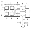
- the drawing shows schematically a block diagram of an electric welding device 1, which the known electronics unit 2 with a controller and power electronics for contains the electric welding, the electrical connection using a welding cable 3 can be produced.
- a welding device especially in Piping systems made of thermoplastic plastic Fittings or fittings as well as the plastic pipes are made, whereby the power is supplied via the welding cable 3.
- Welding equipment welding connections of plastic plates or plastic foils, for example to seal buildings or landfills.
- the welding device 2 contains a detection unit 4 and / or a reading unit 5 and a memory 6.
- the reading unit 5 is in expediently as well as the plug or contacts 7 at the end or at the end area of the welding cable 3 arranged around the on a data carrier of the fitting, Valve or the like provided data to be able to read.
- the one with the fitting or the like hard drive is within the scope of the invention as a Barcode or barcode, a magnetic card, a microchip or the like.
- the parameters characterizing the respective welding process are stored in the memory 6 held ready and can be used if necessary via a data connection 8, for example a parallel interface to a modem or similar, transmitted to the outside or be queried.
- the welding device 2 is also assigned a receiver 10, and expediently in the housing of the welding device with the other electronic components integrated.
- the receiver 10 is part of a positioning system, and preferred of the global positioning system, GPS for short, which is an exact determination and locating an object using satellites installed in orbit enables.
- the signals from the satellites and / or special receiving and transmitting devices on the earth's surface are received by an antenna 12 and in Receiver 10 becomes the exact position of the welded joint and / or the welding machine 2 determined on the earth's surface. Above all, latitude and longitude but also the altitude above sea level and the time determined and saved.
- the data obtained with the receiver 10 are fed to the memory 6 and assigned to the data of the welding process. The preferably under a job number saved welding-specific data are therefore at least with the geographical coordinates added.
- the welding device 2 contains a data transmission system 14, by means of which further data, such as street maps in particular, are loadable.
- a PCM data transmission system is preferably used.
- This data transmission system additionally or alternatively enables the entry of Coordinates and / or correction values and related data are stored in the memory and / or computer 6 supplied. The position can be determined within the scope of the invention also take place exclusively by means of the transmission unit 14.
- the data held in the computer and / or memory 6, namely the welding data just like the position data can, if necessary, via the data connection 8 are transferred to a transfer unit 16.
- the easiest way to transfer is by means of a cable 18 that can be connected if necessary, but also a direct one Plug connection or a wireless transmission can be provided.
- Essential is that the said data is temporarily stored by means of the transfer unit and transported from the welding machine to another computer or the like can.
- the transfer unit 16 expediently contains a writable and if necessary, erasable storage medium, in particular in a non-volatile form can be carried out, for example on a magnetic tape, a magnetic Diskette or digital memory modules is referenced.
- a display or a display unit 20 can also be expediently connected, specifically on the data transmission unit 14.
- This display unit 20 which is designed as a screen, LCD display or the like, enables the position display the welded joint, preferably in connection with city maps, site plans or similar.
- the display unit 20 is designed according to the invention in such a way that that position data can be recorded and in the same way as about the receiver 10 can be entered into the memory or computer 6 and ultimately the welding data be assigned. This enables the exact position of the welding machine to be easily determined and / or the welding fitting, the fitting or the like can be made visible.
- the display unit enables in a particularly expedient manner Correction or defined entry of the position data. With the display unit at the location data obtained by means of the receiver and the antenna 12 with little effort or geographic coordinates.
- mapping unit 22 is provided, which Expediently connectable to the welding device 1 via the data transmission unit 14 is.
- This mapping unit 22 enables the loading or input of City plans, laying plans or the like, which can be displayed in the display unit 20 are.
- the antenna 12 ' with the welding cable 3 coupled.
- the antenna 12 ' is preferred, as is the plug 7 at the end of the Welding cable 3 arranged. Is the welding fitting or the like in one relative arranged a large distance from the welding machine, so the welding cable has a relative length, the antenna 12 'is nevertheless in the immediate vicinity of the fitting, so that a very exact position determination is guaranteed.
Abstract
Description
- 1
- Schweißgerät
- 2
- Elektronikeinheit
- 3
- Schweißkabel
- 4
- Erfassungseinheit
- 5
- Leseeinheit
- 6
- Speicher / Rechner
- 7
- Kontaktelement / Stecker
- 8
- Datenanschluß
- 10
- Empfänger
- 12
- Antenne
- 14
- PCM-Datenübertragungseinheit
- 16
- Übergabeeinheit
- 18
- Kabel
- 20
- Anzeigeeinheit
- 22
- Mappingeinheit
Claims (9)
- Anordnung mit einem Schweißgerät, mittels welchem insbesondere Strom, Spannung und Zeit eines Schweißvorganges vorgebbar und speicherbar sind, wobei das Schweißgerät einen Speicher und/oder Rechner enthält,
dadurch gekennzeichnet,
daß den Schweißdaten Positionsdaten eines Ortungssystems zuordenbar sind. - Anordnung nach Anspruch 1, dadurch gekennzeichnet, daß das Schweißgerät (2) einen Empfänger (10) eines Ortungssystems, insbesondere eines Satellitenortungssystems, aufweist.
- Anordnung nach Anspruch 1 oder 2, dadurch gekennzeichnet, daß das Schweißgerät (2) eine Datenübertragungseinheit (14) aufweist, welcher Positionsdaten zuführbar sind.
- Anordnung nach Anspruch 2 oder 3, dadurch gekennzeichnet, daß den Schweißdaten die mittels des Empfängers (10) und/oder der Datenübertragungseinheit (14) geographischen Kooradinaten vorzugsweise die Längen- und Breitengrade, den Schweißdaten zugeordnet werden, und/oder daß diese Zuordnung mittels eines Rechners und/oder Speichers (6) durchführbar ist.
- Anordnung nach einem der Ansprüche 1 bis 4, dadurch gekennzeichnet, daß die Schweißdaten ebenso wie die Positionsdaten auf eine Übergabeeinheit (16) übertragbar sind.
- Anordnung nach einem der Ansprüche 1 bis 5, dadurch gekennzeichnet, daß das Ortungssystem eine Anzeigeeinheit (20) enthält, mittels welcher Positionsdaten korrigierbar und / oder eingebbar sind.
- Anordnung nach Anspruch 6, dadurch gekennzeichnet, daß eine Mappingeinheit (22) der Anzeigeeinheit (20) zugeordnet ist.
- Anordnung nach einem der Ansprüche 2 bis 7, dadurch gekennzeichnet, daß dem Empfänger (10) eine Antenne (12, 12') Zugeordnet ist und / oder daß die Antenne (12') am Ende oder am Endbereich eines Schweißkabels (3) angeordnet ist.
- Anordnung nach einem der Ansprüche 1 bis 8, dadurch gekennzeichnet, daß eine Leseeinheit (5) vorgesehen ist und / oder daß die Leseeinheit (5) am Ende oder am Endbereich des Schweißkabels (3) angeordnet ist.
Priority Applications (8)
| Application Number | Priority Date | Filing Date | Title |
|---|---|---|---|
| ARP970105919A AR010784A1 (es) | 1996-12-23 | 1997-12-16 | Disposicion con un puesto de soldadura |
| JP9353423A JPH1148340A (ja) | 1996-12-23 | 1997-12-22 | 溶接装置を含む溶接システム |
| BR9705633-2A BR9705633A (pt) | 1996-12-23 | 1997-12-22 | Sistema com um aparelho de solda |
| CZ974157A CZ415797A3 (cs) | 1996-12-23 | 1997-12-22 | Zařízení se svařovacím přístrojem |
| CA002222710A CA2222710A1 (en) | 1996-12-23 | 1997-12-22 | System with a welding apparatus |
| CN97129741A CN1196999A (zh) | 1996-12-23 | 1997-12-23 | 焊接机的配置 |
| AU49231/97A AU4923197A (en) | 1996-12-23 | 1997-12-23 | System with a welding apparatus |
| TR97/01681A TR199701681A2 (xx) | 1996-12-23 | 1997-12-23 | Bir kaynak cihaz� i�in d�zenleme |
Applications Claiming Priority (2)
| Application Number | Priority Date | Filing Date | Title |
|---|---|---|---|
| DE19654122 | 1996-12-23 | ||
| DE19654122A DE19654122C1 (de) | 1996-12-23 | 1996-12-23 | Anordnung mit einem Schweißgerät |
Publications (2)
| Publication Number | Publication Date |
|---|---|
| EP0850748A2 true EP0850748A2 (de) | 1998-07-01 |
| EP0850748A3 EP0850748A3 (de) | 1998-12-30 |
Family
ID=7816090
Family Applications (1)
| Application Number | Title | Priority Date | Filing Date |
|---|---|---|---|
| EP97121276A Withdrawn EP0850748A3 (de) | 1996-12-23 | 1997-12-04 | Anordnung mit einem Schweissgerät |
Country Status (4)
| Country | Link |
|---|---|
| EP (1) | EP0850748A3 (de) |
| AR (1) | AR010784A1 (de) |
| DE (1) | DE19654122C1 (de) |
| ZA (1) | ZA9711452B (de) |
Cited By (7)
| Publication number | Priority date | Publication date | Assignee | Title |
|---|---|---|---|---|
| WO2000036478A1 (de) * | 1998-12-14 | 2000-06-22 | Siemens Aktiengesellschaft | Verteiles steuerungssystem mit lagebestimmung der komponenten |
| EP1149686A2 (de) * | 2000-04-26 | 2001-10-31 | Glynwed Pipe Systems Limited | Steuersystem für Schmelzschweissverfahren |
| GB2361665A (en) * | 2000-04-26 | 2001-10-31 | Glynwed Pipe Systems Ltd | Pipeline forming method and apparatus with GPS |
| EP2320286A1 (de) * | 2009-11-07 | 2011-05-11 | Leister Process Technologies | Verfahren zum Protokollieren von Prozessinformationsdaten |
| GB2477773A (en) * | 2010-02-12 | 2011-08-17 | Kevin Mark Wilkinson | Quality control improvements to the pipe jointing process |
| EP2468443A1 (de) * | 2010-12-22 | 2012-06-27 | Friatec Aktiengesellschaft | System and Verfahren zum Kommunizieren und Verwalten von Schweissinformation |
| DE202016105850U1 (de) | 2016-02-18 | 2017-01-27 | Leister Technologies Ag | Schweißautomat zum überlappenden Verschweißen von Kunststoffbahnen und Übertragungssystem für Schweißinformationen zwischen einem Kunststoffschweißgerät und einem Schweißinformations-Verwaltungsserver |
Families Citing this family (9)
| Publication number | Priority date | Publication date | Assignee | Title |
|---|---|---|---|---|
| CA2265215C (en) * | 1998-04-02 | 2004-06-22 | Lincoln Global, Inc. | Welding monitoring system |
| DE19962103A1 (de) * | 1999-12-22 | 2001-08-09 | Braas Flachdachsysteme Gmbh & | Einrichtung und Verfahren zur Ermittlung von optimalen Parametern zum Betreiben von Handhabungsgeräten oder sonstigen Vorrichtungen zum Heißgasverschweißen |
| DE10059659B4 (de) * | 2000-12-01 | 2004-03-18 | Heinz Soyer Bolzenschweisstechnik Gmbh | Qualitätskontrolle beim Bolzenschweißen |
| EP1265118A1 (de) * | 2001-06-05 | 2002-12-11 | Abb Research Ltd. | Verfahren zur Installationsüberwachung eines mobilen Gerätes |
| DE10221023A1 (de) * | 2002-05-06 | 2003-11-27 | Tech Fachhochschule Wildau | Verfahren und Anordnung zur Qualitätssicherung bei Schweißprozessen sowie ein entsprechendes Computerprogrammprodukt und ein entsprechendes computerlesbares Speichermedium |
| US9138825B2 (en) | 2005-10-07 | 2015-09-22 | Illinois Tool Works Inc. | Wireless communication system for welding-type devices |
| WO2007044135A1 (en) | 2005-10-07 | 2007-04-19 | Illinois Tool Works Inc. | Wireless communication system for welding-type devices |
| US8686318B2 (en) | 2005-10-07 | 2014-04-01 | Illinois Tool Works Inc. | Wireless tracking and inventory monitoring for welding-type devices |
| US10363627B2 (en) | 2014-12-16 | 2019-07-30 | Illinois Tool Works Inc. | Systems and methods for providing location services for a welding power supply |
Citations (3)
| Publication number | Priority date | Publication date | Assignee | Title |
|---|---|---|---|---|
| EP0441650A2 (de) * | 1990-02-08 | 1991-08-14 | Uponor Bv | Schmelz-Kontrolleinheit |
| EP0335010B1 (de) * | 1988-03-30 | 1994-04-06 | Hürner Gmbh | Elektro-Schweissgerät zum selbsttätigen Schweissen von Heizwendel-Fittingen |
| WO1995008432A1 (de) * | 1993-09-24 | 1995-03-30 | Wavin B.V. | Qualitätssicherung bei elektroschweissbaren verbindungselementen |
Family Cites Families (6)
| Publication number | Priority date | Publication date | Assignee | Title |
|---|---|---|---|---|
| JPH029619A (ja) * | 1988-06-28 | 1990-01-12 | Sekisui Chem Co Ltd | 電気溶着装置 |
| JPH07128427A (ja) * | 1993-11-02 | 1995-05-19 | Fujikura Ltd | 地名入力装置 |
| JPH0816622A (ja) * | 1994-06-27 | 1996-01-19 | Blue Line Shiya:Kk | 野外調査データファイルシステム |
| JPH095421A (ja) * | 1995-06-19 | 1997-01-10 | Pacific Consultants Kk | 現地調査データ収集装置 |
| JPH0926060A (ja) * | 1995-07-10 | 1997-01-28 | Mitsui Petrochem Ind Ltd | 配管施工情報管理方法及びそれに使用される樹脂配管融着用コントローラー |
| JPH09242976A (ja) * | 1996-03-12 | 1997-09-16 | Sekisui Chem Co Ltd | 電気溶着装置 |
-
1996
- 1996-12-23 DE DE19654122A patent/DE19654122C1/de not_active Expired - Fee Related
-
1997
- 1997-12-04 EP EP97121276A patent/EP0850748A3/de not_active Withdrawn
- 1997-12-16 AR ARP970105919A patent/AR010784A1/es unknown
- 1997-12-19 ZA ZA9711452A patent/ZA9711452B/xx unknown
Patent Citations (3)
| Publication number | Priority date | Publication date | Assignee | Title |
|---|---|---|---|---|
| EP0335010B1 (de) * | 1988-03-30 | 1994-04-06 | Hürner Gmbh | Elektro-Schweissgerät zum selbsttätigen Schweissen von Heizwendel-Fittingen |
| EP0441650A2 (de) * | 1990-02-08 | 1991-08-14 | Uponor Bv | Schmelz-Kontrolleinheit |
| WO1995008432A1 (de) * | 1993-09-24 | 1995-03-30 | Wavin B.V. | Qualitätssicherung bei elektroschweissbaren verbindungselementen |
Non-Patent Citations (6)
| Title |
|---|
| DATABASE WPI Section EI, Week 9614 Derwent Publications Ltd., London, GB; Class S02, AN 96-132936 XP002082428 -& JP 08 016622 A (BLUE LINE SHA KK) , 19. Januar 1996 * |
| PATENT ABSTRACTS OF JAPAN vol. 014, no. 144 (M-0951), 19. März 1990 -& JP 02 009619 A (SEKISUI CHEM CO LTD), 12. Januar 1990 * |
| PATENT ABSTRACTS OF JAPAN vol. 095, no. 008, 29. September 1995 -& JP 07 128427 A (FUJIKURA LTD), 19. Mai 1995 * |
| PATENT ABSTRACTS OF JAPAN vol. 097, no. 005, 30. Mai 1997 -& JP 09 005421 A (PACIFIC CONSULTANTS KK), 10. Januar 1997 * |
| PATENT ABSTRACTS OF JAPAN vol. 097, no. 005, 30. Mai 1997 -& JP 09 026060 A (MITSUI PETROCHEM IND LTD), 28. Januar 1997 * |
| PATENT ABSTRACTS OF JAPAN vol. 098, no. 001, 30. Januar 1998 -& JP 09 242976 A (SEKISUI CHEM CO LTD), 16. September 1997 * |
Cited By (12)
| Publication number | Priority date | Publication date | Assignee | Title |
|---|---|---|---|---|
| WO2000036478A1 (de) * | 1998-12-14 | 2000-06-22 | Siemens Aktiengesellschaft | Verteiles steuerungssystem mit lagebestimmung der komponenten |
| US6889099B2 (en) | 1998-12-14 | 2005-05-03 | Siemens Aktiengesellschaft | Distributed control system and an associated system component for the distributed control system |
| EP1149686A2 (de) * | 2000-04-26 | 2001-10-31 | Glynwed Pipe Systems Limited | Steuersystem für Schmelzschweissverfahren |
| GB2361665A (en) * | 2000-04-26 | 2001-10-31 | Glynwed Pipe Systems Ltd | Pipeline forming method and apparatus with GPS |
| EP1150055A2 (de) * | 2000-04-26 | 2001-10-31 | Glynwed Pipe Systems Limited | Verfahren und Vorrichtung zur Herstellung eines Rohrsystems |
| EP1149686A3 (de) * | 2000-04-26 | 2002-02-13 | Glynwed Pipe Systems Limited | Steuersystem für Schmelzschweissverfahren |
| EP1150055A3 (de) * | 2000-04-26 | 2002-05-29 | Glynwed Pipe Systems Limited | Verfahren und Vorrichtung zur Herstellung eines Rohrsystems |
| GB2361665B (en) * | 2000-04-26 | 2004-07-07 | Glynwed Pipe Systems Ltd | Improvements in and relating to pipe forming systems |
| EP2320286A1 (de) * | 2009-11-07 | 2011-05-11 | Leister Process Technologies | Verfahren zum Protokollieren von Prozessinformationsdaten |
| GB2477773A (en) * | 2010-02-12 | 2011-08-17 | Kevin Mark Wilkinson | Quality control improvements to the pipe jointing process |
| EP2468443A1 (de) * | 2010-12-22 | 2012-06-27 | Friatec Aktiengesellschaft | System and Verfahren zum Kommunizieren und Verwalten von Schweissinformation |
| DE202016105850U1 (de) | 2016-02-18 | 2017-01-27 | Leister Technologies Ag | Schweißautomat zum überlappenden Verschweißen von Kunststoffbahnen und Übertragungssystem für Schweißinformationen zwischen einem Kunststoffschweißgerät und einem Schweißinformations-Verwaltungsserver |
Also Published As
| Publication number | Publication date |
|---|---|
| ZA9711452B (en) | 1998-06-24 |
| DE19654122C1 (de) | 1998-01-29 |
| EP0850748A3 (de) | 1998-12-30 |
| AR010784A1 (es) | 2000-07-12 |
Similar Documents
| Publication | Publication Date | Title |
|---|---|---|
| EP0850748A2 (de) | Anordnung mit einem Schweissgerät | |
| DE69532308T2 (de) | Ortungsanlage | |
| DE102011106139B4 (de) | Verfahren und Vorrichtung zum Bestimmen einer von mindestens einer Baumaschine oder Abbaumaschine mit einer Fräswalze gefrästen Fläche | |
| EP0565191A2 (de) | Anordnung zur Positionsbestimmung eines Landfahrzeugs | |
| DE2423113A1 (de) | Verfahren und einrichtung zur fehlerpruefung magnetisierbarer objekte durch messung von magnetflussaenderungen | |
| DE2156110A1 (de) | Verfahren und Vorrichtung zur Bohrlochführung | |
| DE19625561A1 (de) | Verfahren zur Kursregelung von Wasserfahrzeugen über Grund | |
| EP1141620B1 (de) | Georeferenziertes prüfsystem | |
| DE202004004945U1 (de) | Lotstab für Vermessungssysteme | |
| DE102017112972A1 (de) | Feldgerät der Automatisierungstechnik | |
| DE3227547A1 (de) | Navigationsanlage | |
| EP0972209B1 (de) | Ortungsvorrichtung für fahrzeuge | |
| DE102018220782A1 (de) | Lokalisierung eines Fahrzeugs anhand von dynamischen Objekten | |
| DE4033831A1 (de) | Navigationssystem fuer einen beweglichen koerper | |
| DE4340285A1 (de) | Ereignisregistrierung in Verbindung mit geographischer Ortsbestimmung bei Fahrzeugen, insbesondere Nutzfahrzeugen | |
| DE10122840A1 (de) | Spleißeinrichtung zum Verspleißen von Lichtwellenleitern | |
| EP2223148A1 (de) | Verfahren und vorrichtung zur ortung eines fahrzeugs | |
| DE2062575A1 (de) | Verfahren und Vorrichtung fur die Registrierung einer Schiffsposition | |
| DE102018007632A1 (de) | System zur Bestimmung der Position von Verkehrsleiteinrichtungen | |
| CH639482A5 (de) | Messanordnung zur absteckung und aufmessung mittels eines elektronischen tachymeters. | |
| DE102017204535A1 (de) | Verfahren und System zum Ergänzen einer auf einem Zentralrechner gespeicherten digitalen Karte eines Verkehrswegenetzes | |
| DE102016004370A1 (de) | Verfahren zur Positionsbestimmung von Fahrzeugen | |
| DE10148224A1 (de) | Verfahren und System zur Ermittlung von Kartendaten | |
| DE102020206999A1 (de) | Verfahren zur Feststellung der Position eines Fahrzeugs | |
| DE102019218180A1 (de) | Verfahren und System zum Zuordnen von Koordinaten |
Legal Events
| Date | Code | Title | Description |
|---|---|---|---|
| PUAI | Public reference made under article 153(3) epc to a published international application that has entered the european phase |
Free format text: ORIGINAL CODE: 0009012 |
|
| AK | Designated contracting states |
Kind code of ref document: A2 Designated state(s): AT BE CH DE DK ES FI FR GB GR IE IT LI LU MC NL PT SE |
|
| AX | Request for extension of the european patent |
Free format text: AL PAYMENT 971204;LT PAYMENT 971204;LV PAYMENT 971204;MK;RO PAYMENT 971204;SI PAYMENT 971204 |
|
| PUAL | Search report despatched |
Free format text: ORIGINAL CODE: 0009013 |
|
| AK | Designated contracting states |
Kind code of ref document: A3 Designated state(s): AT BE CH DE DK ES FI FR GB GR IE IT LI LU MC NL PT SE |
|
| AX | Request for extension of the european patent |
Free format text: AL PAYMENT 971204;LT PAYMENT 971204;LV PAYMENT 971204;MK;RO PAYMENT 971204;SI PAYMENT 971204 |
|
| AKX | Designation fees paid |
Free format text: AT BE CH DE DK ES FI FR GB GR IE IT LI LU MC NL PT SE |
|
| AXX | Extension fees paid |
Free format text: AL PAYMENT 19971204;LT PAYMENT 19971204;LV PAYMENT 19971204;RO PAYMENT 19971204;SI PAYMENT 19971204 |
|
| STAA | Information on the status of an ep patent application or granted ep patent |
Free format text: STATUS: THE APPLICATION IS DEEMED TO BE WITHDRAWN |
|
| 18D | Application deemed to be withdrawn |
Effective date: 19990701 |