EP0849150A2 - Dispositif de commande de frein. - Google Patents
Dispositif de commande de frein. Download PDFInfo
- Publication number
- EP0849150A2 EP0849150A2 EP97309479A EP97309479A EP0849150A2 EP 0849150 A2 EP0849150 A2 EP 0849150A2 EP 97309479 A EP97309479 A EP 97309479A EP 97309479 A EP97309479 A EP 97309479A EP 0849150 A2 EP0849150 A2 EP 0849150A2
- Authority
- EP
- European Patent Office
- Prior art keywords
- hand
- bar
- operating device
- brake
- brake operating
- Prior art date
- Legal status (The legal status is an assumption and is not a legal conclusion. Google has not performed a legal analysis and makes no representation as to the accuracy of the status listed.)
- Granted
Links
Images


Classifications
-
- B—PERFORMING OPERATIONS; TRANSPORTING
- B62—LAND VEHICLES FOR TRAVELLING OTHERWISE THAN ON RAILS
- B62L—BRAKES SPECIALLY ADAPTED FOR CYCLES
- B62L3/00—Brake-actuating mechanisms; Arrangements thereof
- B62L3/02—Brake-actuating mechanisms; Arrangements thereof for control by a hand lever
-
- B—PERFORMING OPERATIONS; TRANSPORTING
- B62—LAND VEHICLES FOR TRAVELLING OTHERWISE THAN ON RAILS
- B62K—CYCLES; CYCLE FRAMES; CYCLE STEERING DEVICES; RIDER-OPERATED TERMINAL CONTROLS SPECIALLY ADAPTED FOR CYCLES; CYCLE AXLE SUSPENSIONS; CYCLE SIDE-CARS, FORECARS, OR THE LIKE
- B62K21/00—Steering devices
- B62K21/12—Handlebars; Handlebar stems
- B62K21/125—Extensions; Auxiliary handlebars
-
- B—PERFORMING OPERATIONS; TRANSPORTING
- B62—LAND VEHICLES FOR TRAVELLING OTHERWISE THAN ON RAILS
- B62K—CYCLES; CYCLE FRAMES; CYCLE STEERING DEVICES; RIDER-OPERATED TERMINAL CONTROLS SPECIALLY ADAPTED FOR CYCLES; CYCLE AXLE SUSPENSIONS; CYCLE SIDE-CARS, FORECARS, OR THE LIKE
- B62K23/00—Rider-operated controls specially adapted for cycles, i.e. means for initiating control operations, e.g. levers, grips
- B62K23/02—Rider-operated controls specially adapted for cycles, i.e. means for initiating control operations, e.g. levers, grips hand actuated
- B62K23/06—Levers
-
- Y—GENERAL TAGGING OF NEW TECHNOLOGICAL DEVELOPMENTS; GENERAL TAGGING OF CROSS-SECTIONAL TECHNOLOGIES SPANNING OVER SEVERAL SECTIONS OF THE IPC; TECHNICAL SUBJECTS COVERED BY FORMER USPC CROSS-REFERENCE ART COLLECTIONS [XRACs] AND DIGESTS
- Y10—TECHNICAL SUBJECTS COVERED BY FORMER USPC
- Y10T—TECHNICAL SUBJECTS COVERED BY FORMER US CLASSIFICATION
- Y10T74/00—Machine element or mechanism
- Y10T74/20—Control lever and linkage systems
- Y10T74/20207—Multiple controlling elements for single controlled element
- Y10T74/20213—Interconnected
-
- Y—GENERAL TAGGING OF NEW TECHNOLOGICAL DEVELOPMENTS; GENERAL TAGGING OF CROSS-SECTIONAL TECHNOLOGIES SPANNING OVER SEVERAL SECTIONS OF THE IPC; TECHNICAL SUBJECTS COVERED BY FORMER USPC CROSS-REFERENCE ART COLLECTIONS [XRACs] AND DIGESTS
- Y10—TECHNICAL SUBJECTS COVERED BY FORMER USPC
- Y10T—TECHNICAL SUBJECTS COVERED BY FORMER US CLASSIFICATION
- Y10T74/00—Machine element or mechanism
- Y10T74/20—Control lever and linkage systems
- Y10T74/20207—Multiple controlling elements for single controlled element
- Y10T74/20256—Steering and controls assemblies
- Y10T74/20268—Reciprocating control elements
- Y10T74/2028—Handle bar type
- Y10T74/20287—Flexible control element
-
- Y—GENERAL TAGGING OF NEW TECHNOLOGICAL DEVELOPMENTS; GENERAL TAGGING OF CROSS-SECTIONAL TECHNOLOGIES SPANNING OVER SEVERAL SECTIONS OF THE IPC; TECHNICAL SUBJECTS COVERED BY FORMER USPC CROSS-REFERENCE ART COLLECTIONS [XRACs] AND DIGESTS
- Y10—TECHNICAL SUBJECTS COVERED BY FORMER USPC
- Y10T—TECHNICAL SUBJECTS COVERED BY FORMER US CLASSIFICATION
- Y10T74/00—Machine element or mechanism
- Y10T74/20—Control lever and linkage systems
- Y10T74/20396—Hand operated
- Y10T74/20402—Flexible transmitter [e.g., Bowden cable]
- Y10T74/2042—Flexible transmitter [e.g., Bowden cable] and hand operator
- Y10T74/20438—Single rotatable lever [e.g., for bicycle brake or derailleur]
Definitions
- the present invention generally relates to a brake operating device with a pair of hand portions for operating brakes from two distinct gripping positions on the handle bar. More specifically, the present invention relates to a brake operating device mounted on an extension bar or bar end of a handle bar having two distinct gripping positions, i.e., one gripping position on the extension bar or bar end and a second gripping position on the handle bar.
- Bicycling is becoming an increasingly more popular form of recreation as well as a means of transportation.
- the road racing bikes typically have a drop-type handle bar with a generally straight center section and a pair of forwardly and downwardly extending curved sections mounted on each end of the center sections.
- the mountain bikes and the hybrid bikes typically have a generally straight horizontal handle bar with a pair of optional extension members or bar ends attached to each end of the straight handle bar. These bar ends or extension members are typically positioned to extend upwardly from the straight handle bar section and curve inwardly towards the center of the bike.
- Bicycle brakes are typically operated by brake operating devices mounted on the handle bar of the bicycle.
- a bicycle is provided with front and rear brakes such that a pair of brake operating devices are attached to the handle bar. Since many handle bars have two distinct and separate gripping positions for the rider, it is desirable for the rider to quickly and conveniently operate the brake operating devices in both positions. In other words, it is desirable for the rider to be able to operate the brake without having to change his or her grip on the handle bar. Accordingly, it is desirable to have brake operating devices which are capable of being operated in either of the two distinct gripping or riding positions.
- a handle bar assembly according to Claim 38.
- Preferred embodiments of the present invention provide a brake operating device which permits the rider to operate the brakes from two distinct positions without having to release a grip from the handle bars in either of the two gripping or riding positions.
- Preferred embodiments of the present invention provide a brake operating device which provides the rider with substantially the same feel when operating the brakes from either of the two gripping or riding positions.
- Preferred embodiments of the present invention provide a brake operating device which mounts on the free end of an extension bar or bar end.
- the extension bar or bar end and the brake operating device are formed as an integral unit which is attached to the straight section of the main handle bar.
- the brake operating device can have a pair of separate and distinct hand portions or levers which can either pivot together or pivot independently of each other.
- first and second hand portions of the brake lever could be formed as one single lever with the second lever coupled to the end of the first lever.
- the brake operating device can be a separate unit which can be clamped to a bar end or a portion of a handle bar.
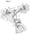
- a pair of attachment assemblies 10 in accordance with a first embodiment the present invention is illustrated as being coupled to a handle bar 12 of bicycle 14 for operating its front and rear brakes 16 (only front brake shown) via a pair of control wires 18.
- Bicycle 14 and brakes 16 are well known in the art, and thus, will not be discussed or illustrated in detail herein. While bicycle 14 is preferably either a mountain bike or a hybrid bike, it will be apparent to those skilled in the art that attachment assemblies 10 do not depend upon the type of bicycle, but rather depend upon the shape of handle bar 12. In fact, attachment assemblies 10 can be utilized on motorized vehicles having handle bars such as motorcycles , all terrain vehicles and the like.
- handle bar 12 is a generally straight, horizontal member attached to the bicycle frame 19.
- handle bar 12 is attached at its center portion to frame 19.
- the ends of handle bar 12 has a pair of primary grip portions 22 formed thereon.
- grip portions 22 have resilient tubular hand grips 24 positioned along grip portions 22 of handle bar 12.
- Handle bar 12 and hand grips 24 are well known in the art, and thus will not be discussed or illustrated in detail herein.
- a pair of shifting mechanisms 20 can be coupled to handle bar 12 for shifting the gears of bicycle 14 in a conventional manner.
- Each of the shifting mechanisms 20 has a pair of primary shifting levers 20a and 20b and a pair of secondary shifting levers 20c and 20d.
- Primary shifting levers 20a and 20b are coupled to shifting body 21 which in turn is fixedly coupled to handle bar 12.
- the operation of shifting mechanism 20 by primary shifting levers 20a and 20b is well known in the art, and thus, the operation of shifting mechanism 20 via primary shifting levers 20a and 20b will not be discussed or illustrated in detail herein.
- One of the primary shifting levers 20a and 20b shifts the front or back derailleur up, while the other one of the primary shifting levers shifts the front or rear derailleur down.
- Secondary shifting levers 20c and 20d are coupled to free end 38 of extension bar 30. Secondary shifting levers 20c and 20d are designed to remotely operate primary shifting levers 20a and 20b, respectively. In other words, one of the secondary levers 20c and 20d shifts the front or rear derailleur up, while the other one shifts the front or rear derailleur down. Shifting cable 23 interconnects shifting levers 20a and 20c together, while shifting cable 25 interconnects shifting levers 20b and 20d together. Alternatively, cables 23 and 25 can be connected directly to the mechanism of main shifting body 21. It will be apparent to those skilled in the art that the rider can control the main shifting body 21 by engaging the primary or secondary shifting levers 20a - 20d.
- main shifting body 21 When one of the secondary shifting levers 20c and 20d are depressed by the rider, this will cause tension in one of the shifting cables 23 and 25 which in turn adjust the mechanism within main shifting body 21 for shifting up or down in gears of bicycle 14.
- the mechanism of main shifting body 21 is well known in the art as well as its operation of either the front or rear derailleur. Therefore, its operation will not be discussed or illustrated herein.
- handle bar 12 is illustrated as being generally straight, it will be apparent to those skilled in the art that handle bar 12 can be bent to a variety of conventional configurations as needed and/or desired.
- each of the grip portions 22 of handle bar 12 has a center longitudinal axis A, which in this embodiment are coaxial, but which in handle bars of other different shapes can be non coaxial.
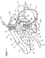
- Attachment assemblies 10 are substantially identical to each other but are mirror images of each other such that they can be releasably attached to the free ends of handle bar 12 adjacent grip portions 22. Since the left and right attachment assemblies 10 are substantially identical, like reference numerals will be utilized to indicate similar parts in discussing and illustrating the present invention herein. Moreover, only the right attachment assembly will be illustrated in Figs. 2-4.
- Each of the attachment assemblies 10 includes an extension bar or bar end 30 with a brake operating device 32 coupled thereto.
- Extension bar 30 is typically known as a bar end within the bicycle art. A typical bar end is illustrated in U.S. Patent No. 5,299,466 to Heilbron et al., which is included as Appendix 1 hereto. More specifically, one end of each extension bar 30 is coupled to one of the free ends of handle bar 12 adjacent one of the grip portions 22, while the brake operating device 32 is coupled to the other end of extension bar 30.
- Extension bar 30 forms a secondary grip portion which preferably extends upwardly and outwardly from handle bar 12 and bends slightly inwardly towards the center plane of bicycle 12.
- handle bar 12 in conjunction with extension bar 30 provides the rider with a pair of distinct and separate gripping or riding positions.
- the rider typically uses the grip portions 22 of the handle bar 12 so that he or she can lean forward into a position from which he or she can apply greater force to the pedals of the bicycle 14.
- the rider uses the extension bars 30 for a more upright and relaxed ride.
- the brake operating device 32 is arranged such that the rider can operate the associated brake 16 in either of the two gripping or riding positions.
- Extension bar 30 has a first clamping end 34, a middle grip portion 36 and a second free end 38.
- First clamping end 34 has a tubular clamp 40 which receives one end of handle bar 12 adjacent one of its grip portions 22.
- tubular clamp 40 is a split tube with a screw 41 for tightening clamp 40 about the end of handle bar 12.
- extension bar 30 is adjustable relative to handle bar 12 for changing the relative angular position therebetween.
- clamp 40 is integrally formed at one end of middle grip portion 36.
- Middle grip portion 36 is preferably a curved member which integrally formed with clamp 40 and a part of brake operating device 32.
- middle grip portion 36 is contoured to comfortably fit a rider's hand.
- middle grip portion 36 will typically extend upwardly and outwardly from handle bar 12 and curve slightly inwardly towards the center plane of bicycle 14.
- Middle grip portion 36 can be constructed of a single material or can be a composite member constructed of one or more parts, preferably two halves as seen in Figs. 2-5.
- middle grip portion 36 can have an upper portion 42 formed out of a hard, rigid metallic material and a lower portion 44 constructed of another material such as a hard rigid plastic material. The upper and lower portions 42 and 44 can be coupled together by a pair of fasteners 46.
- Brake operating device 32 is preferably coupled to upper portion 42 of middle grip portion 36 adjacent second free end 38 of extension bar 30 along its inner gripping surface 36a. Accordingly, the upper gripping surface 36b, the outer gripping surface 36c and the lower gripping surface 36d of the middle grip portion 36 adjacent brake operating device 32 is substantially unobstructed by brake operating device 32. This allows the rider to grip the inner, upper, outer and lower gripping surfaces 36a - 36d of middle grip portion 36 as necessary. In other words, brake operating device 32 is offset inwardly from middle grip portion 36 such that the rider can grip middle grip portion 36 of extension bar 30 adjacent brake operating device 32.
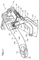
- Brake operating device 32 basically includes a lever bracket 50 coupled to extension bar 30, a brake lever 52 pivotally coupled to lever bracket 50 by a pivot pin 54 about a pivot axis B, a spring 56 coupled between lever bracket 50 and brake lever 52, and a retaining portion or member 58 coupled to brake lever 52 for coupling one of the control wires 18 thereto.
- brake operating device 32 is designed to operate one of the brakes 16 of bicycle 14 when the rider's hand is either on grip portion 22 of handle bar 12 or grip portion 36 of extension bar 30. Moreover, brake operating device 32 is designed to provide the rider with substantially the same feel in applying the brakes regardless of which of the two gripping positions the rider's hands are in. In other words, brake operating device 32 is designed so that substantially the same grip dimension is provided between brake lever 52 and each of the grip portions 22 and 36. Moreover, the lever arms created by brake lever 52 and retaining member 58 relative to pivot pin 54 are preferably substantially identical to the rider whether the rider grips the brake lever 52 from either grip portion 22 or grip portion 36.
- Lever bracket 50 in the first embodiment is preferably inseparably formed with the upper half of middle grip portion 36 of extension bar 30.
- lever bracket 50 is a one-piece, unitary part of upper portion 42 of middle grip portion 36, i.e., not separable from middle grip portion 36.
- lever bracket 50 can be integrally coupled to middle grip portion 36 such that it performs as an integrated member or portion of extension bar 30.
- the term "integral” refers to a part that can be fixedly coupled to another part, while the phrase "one-piece, unitary” refers to an element which is not constructed of several separable pieces.
- lever bracket 50 is preferably offset from middle grip portion 36, as mentioned above, so that the rider can grip middle grip portion 36 adjacent lever bracket 50, as needed or desired.
- lever bracket 50 preferably includes a connecting portion 60, a pair of side walls 62 extending downwardly from connecting portion 60, a front wall 64 extending between side walls 62, and a rear stop wall 66 extending between side walls 62. Also, a control wire support 68 is formed at the front lower end of front wall 64 for receiving and securing a portion of one of the control wires 18 thereto in a conventional manner.
- side walls 62 are spaced apart from each other so as to form a cavity for receiving a portion of brake lever 52 therebetween. Also, a pivot hole 70 is formed in each of the side walls 62 for receiving pivot pin 54 therein to pivotally couple brake lever 52 thereto.
- front wall 64 is designed to limit the forward pivotal movement of brake lever 52 which is biased forwardly by spring 56 to a release position.
- brake lever 52 abuts against front wall 64, brake lever 52 is in its release position.
- the control wire 18 attached to brake lever 52 is let out to open the associated brake 16.
- Control wire support 68 is preferably a tubular member having internal threads for threadedly receiving a wire adjustment nut 69. Also, control support 68 preferably has a slot 72 for inserting one of the control wires 18 therethrough during attachment of control wire 18 to brake operating device 32. Control wire support 68 is a relatively conventional type structure, and thus, will not be discussed or illustrated in further detail.
- Brake lever 52 includes a connecting portion 76, a first hand portion 78 outwardly from connecting portion 76 in a first direction and a second hand portion 80 extending outwardly from connecting portion 76 in a second direction.
- Portions 76, 78 and 80 can all be constructed as a one-piece, unitary member or could be constructed of several pieces as shown in the drawings.
- brake lever 52 can be constructed of two pieces with a first piece including first hand portion 78 and first half of connecting portion 76, and a second piece including second hand portion 80 and a second half of connecting portion 76.
- the first and second halves of connecting portion 76 are fixedly coupled together by a fastener or rivet (not shown) such that first and second hand portions 78 and 80 pivot together.
- connecting portion 76 can be constructed such that first hand portion 78 can move independently of second hand portion 80, or vice-a-versa.
- Connecting portion 76 has a pivot hole 82 for receiving pivot pin 54 therethrough for pivotally coupling brake lever 52 thereto.
- first and second hand portions 78 and 80 are swingable about the pivot axis or point of pivot pin 54 from a release position to a brake position.
- Connecting portion 76 also has a recess for receiving a portion of spring 56 to bias brake lever 52 to its release position.
- First hand portion 78 lies on one side of a center plane of lever bracket 50, while second hand portion 80 lies on the opposite side of the center plane of lever bracket 50.
- First hand portion 78 is positioned generally parallel and adjacent middle grip portion 36 of extension bar 30 to permit the rider's hand to grasp first hand portion 78 from the middle grip portion 36 of extension bar 30.
- First hand portion 78 has its first end coupled to the lower end of connecting portion 76 via an intermediate or arm portion 86. Intermediate portion 86 extends substantially perpendicularly between connecting portion 76 and hand portion 78.
- the second end of second hand portion 78 is preferably a free end.
- First hand portion 78 is also preferably shaped such that it does not extend outwardly relative to extension bar 30. In other words, if the bicycle 14 should fall and the extension bar 30 should hit the ground, first hand portion 78 should be positioned inwardly from the outer gripping surface 36c of middle grip portion 36.
- Second hand portion 80 is preferably positioned generally parallel and adjacent the grip portion 22 of handle bar 12 to permit the rider's hand to grasp second hand portion 80 from grip portion 22 of handle bar 12.
- Second hand portion 80 has a first end coupled to connecting portion 76 via an intermediate or arm portion 88 and a second free end.
- Intermediate portion 88 extends outwardly from connecting portion 76 such that hand portion 80 is spaced to one side of connecting portion 76.
- second hand portion 80 is designed such that it receives a single finger of the rider's hand.
- second hand portion 80 can be designed such that the rider can grasp second hand portion 80 with more than one finger, i.e., second hand portion 80 can be made longer as needed and/or desired.
- second hand portion 80 is generally parallel to grip portion 22 of handle bar 12, it will be apparent to those skilled in the art that second hand portion 80 forms an acute angle with grip portion 22 of handle bar 12.
- Intermediate portion 88 preferably includes a hole for mounting retaining portion or member 58 thereto via pin 90.
- pin 90 a hole for mounting retaining portion or member 58 thereto via pin 90.
- Retaining member 58 is preferably a conventional U-shaped metal bracket which is well-known in the art, and thus, will not be discussed in detail herein.
- Spring 56 is preferably a torsion spring which is positioned about pivot pin 54 and located within a recess of connecting portion 76 of brake lever 52 such that a first end 92 of spring 56 engages brake lever 52 and a second end 94 of spring 56 engages a portion of lever bracket 50.
- spring 56 normally biases brake lever 52 relative to lever bracket 50 and extension bar 30 to a release position where connecting portion 76 engages front wall 64.
- first and second hand portions 78 and 80 in their release positions have their points of force F1 and F2 spaced no greater than approximately 45° apart from each other as measured about the pivot point or pivot axis of pivot pin 54.
- the point of force F1 for hand portion 78 is located approximately 1 inch from the effective free end of hand portion 78.
- the point of force F2 for hand portion 80 includes all of the operative surface of hand portion 80 which is generally parallel to grip portion 22 and within the rider's grasp.
- the angle ⁇ formed between the points of force F1 and F2 is approximately 4° apart as measured about pivot axis B as seen in Fig. 3.
- the preferred range for angle ⁇ is 0° - 36 °.
- the lever arm created between pivot pin 54 and connection point of pin 90 is identical for each of the first and second hand portions 78 and 80.
- the lever arms formed between the pivot point or pivot axis of pivot pin 54 and the points of force F1 and F2 of hand portions 78 and 80 are preferably substantially the same.
- Middle grip portion 36 and hand portions 78 and 80 are configured such that the grip dimension between first hand portion 78 and middle grip portion 36 is substantially similar to the grip dimension between second hand portion 80 and grip portion 22 of handle bar 12.
- the amount of travel of hand portions 78 and 80 are also substantially identical in view of the above discussed relationship.
- attachment assembly 110 is illustrated in accordance with a second embodiment of the present invention.
- attachment assembly 110 is substantially identical to attachment assembly 10, discussed above, except that brake lever 152 of this embodiment has been modified to provide a larger angle between the points of force F1 and F2 of hand portions 178 and 180.
- brake lever 152 of this embodiment has been modified to provide a larger angle between the points of force F1 and F2 of hand portions 178 and 180.
- attachment assembly 110 will not be discussed or illustrated in as much detail as the first embodiment since it will be apparent to those skilled in the art that similar features of the first embodiment apply to this second embodiment.
- attachment assembly 110 includes an extension bar or bar end 130 with a brake operating device 132 coupled thereto. More specifically, extension bar 130 is adapted to be coupled to one of the free ends of handle bar 12 adjacent one of the grip portions 22, while the brake operating device 132 is coupled to the other end of extension bar 130. Extension bar 130 forms a secondary grip portion which preferably extends upwardly and outwardly from handle bar 12 and bends slightly inwardly towards the center plane of the bicycle.
- Extension bar 130 has a first clamping end 134, a middle grip portion 136 and a second free end 138.
- First clamping end 134 has a tubular clamp 140 which receives one end of handle bar 12 adjacent one of its grip portions 22.
- tubular clamp 140 is a split tube with a screw for tightening clamp 140 about the end of handle bar 12.
- extension bar 130 is adjustable relative to handle bar 12 for changing the relative angular position therebetween.
- clamp 140 is integrally formed at one end of middle grip portion 136.
- Brake operating device 132 is preferably coupled to middle grip portion 136 adjacent second free end 138 of extension bar 130 along its inner gripping surface 136a. This allows the rider to grip the inner, upper, outer and lower gripping surfaces of middle grip portion 136 as necessary. In other words, brake operating device 132 is offset inwardly from middle grip portion 136 such that the rider can grip middle grip portion 136 of extension bar 130 adjacent brake operating device 132.
- Brake operating device 132 basically includes a lever bracket 150 coupled to extension bar 130, a brake lever 152 pivotally coupled to lever bracket 150 by a pivot pin 154 about a pivot axis B, a spring 156 coupled between lever bracket 150 and brake lever 152, and a retaining portion or member 158 coupled to brake lever 152 for coupling one of the control wires 118 thereto.
- Brake operating device 132 is designed to operate one of the brakes of bicycle when the rider's hand is either on grip portion 22 of handle bar 12 or grip portion 136 of extension bar 130. Moreover, brake operating device 132 is designed to provide the rider with substantially the same feel in applying the brakes regardless of which of the two gripping positions the rider's hands are in. In other words, brake operating device 132 is designed so that substantially the same grip dimension is provided between brake lever 152 and each of the grip portions 22 and 136. Moreover, the lever arms created by brake lever 152 and retaining member 158 relative to pivot pin 154 are preferably substantially identical to the rider whether the rider grips the brake lever 152 from either grip portion 22 or grip portion 136.
- Brake lever 152 includes a connecting portion 176, a first hand portion 178 outwardly from connecting portion 176 in a first direction and a second hand portion 180 extending outwardly from connecting portion 176 in a second direction.
- First hand portion 178 lies on one side of a center plane of lever bracket 150, while second hand portion 180 lies on an the opposite side of the center plane of lever bracket 150.
- First hand portion 178 is positioned generally parallel and adjacent middle grip portion 136 of extension bar 130 to permit the rider's hand to grasp first hand portion 178 from the middle grip portion 136 of extension bar 130.
- First hand portion 178 has its first end coupled to the lower end of connecting portion 176 via an intermediate or arm portion 186.
- Intermediate portion 186 extends substantially perpendicularly between connecting portion 176 and hand portion 178.
- the second end of second hand portion 178 is preferably a free end.
- Second hand portion 180 is preferably positioned generally parallel and adjacent the grip portion 22 of handle bar 12 to permit the rider's hand to grasp second hand portion 180 from grip portion 22 of handle bar 12.
- Second hand portion 180 has a first end coupled to connecting portion 176 via an intermediate or arm portion 188 and a second free end.
- Intermediate portion 188 extends outwardly from connecting portion 176 such that hand portion 180 is spaced to one side of connecting portion 176.
- first and second hand portions 178 and 180 in their release positions have their points of force F1 and F2 spaced no greater than approximately 45° apart from each other as measured about the pivot point or pivot axis of pivot pin 154.
- the point of force F1 for hand portion 178 is located approximately 1 inch from the effective free end of hand portion 178.
- the point of force F2 for hand portion 180 includes all of the operative surface of hand portion 180 which is generally parallel to grip portion 122 and within the rider's grasp.
- the angle ⁇ formed between the points of force F1 and F2 is approximately 36° apart as measured about pivot axis B.
- lever arm created between pivot pin 154 and connection point of pin 190 is identical for each of the first and second hand portions 178 and 180.
- lever arms formed between the pivot point or pivot axis of pivot pin 154 and the points of force F1 and F2 of hand portions 78 and 80 are preferably substantially the same.
- Middle grip portion 136 and hand portions 178 and 180 are configured such that the grip dimension between first hand portion 178 and middle grip portion 136 is substantially similar to the grip dimension between second hand portion 180 and grip portion 22 of handle bar 12.
- the amount of travel of hand portions 178 and 180 are also substantially identical in view of the above discussed relationship.
- attachment assembly 210 is illustrated in accordance with a third embodiment of the present invention.
- attachment assembly 210 is substantially identical to attachment assembly 10, discussed above, except that brake lever 252 of this embodiment has been modified to be substantially L-shaped with second hand portion 280 coupled to the end of first hand portion 278.
- brake lever 252 of this embodiment has been modified to be substantially L-shaped with second hand portion 280 coupled to the end of first hand portion 278.
- attachment assembly 210 will not be discussed or illustrated in as much detail as the first embodiment since it will be apparent to those skilled in the art that similar features of the first embodiment apply to this third embodiment.
- Attachment assembly 210 includes an extension bar or bar end 230 with a brake operating device 232 coupled thereto. More specifically, extension bar 230 is adapted to be coupled to one of the free ends of handle bar 212 adjacent one of the grip portions 222, while the brake operating device 232 is coupled to the other end of extension bar 230. Extension bar 230 forms a secondary grip portion which preferably extends upwardly and outwardly from handle bar 212 and bends slightly inwardly towards the center plane of the bicycle.
- Extension bar 230 has a first clamping end 234, a middle grip portion 236 and a second free end 238.
- First clamping end 234 has a tubular clamp 240 which receives one end of handle bar 212 adjacent one of its grip portions 222.
- tubular clamp 240 is a split tube with a screw for tightening clamp 240 about the end of handle bar 212.
- extension bar 230 is adjustable relative to handle bar 212 for changing the relative angular position therebetween.
- clamp 240 is integrally formed at one end of middle grip portion 236.
- Brake operating device 232 is preferably coupled to middle grip portion 236 adjacent second free end 238 of extension bar 230 along its inner gripping surface 236a. This allows the rider to grip the inner, upper, outer and lower gripping surfaces of middle grip portion 236 as necessary. In other words, brake operating device 232 is offset inwardly from middle grip portion 236 such that the rider can grip middle grip 236 of extension bar 230 adjacent brake operating device 232.
- Brake operating device 232 basically includes a lever bracket 250 coupled to extension bar 230, a brake lever 252 pivotally coupled to lever bracket 250 by a pivot pin 254 about a pivot axis B, a spring 256 coupled between lever bracket 250 and brake lever 252, and a retaining portion or member 258 coupled to brake lever 252 for coupling one of the control wires 218 thereto.
- Brake lever 252 includes a connecting portion 276, a first hand portion 278 outwardly from connecting portion 276 in a first direction and a second hand portion 280 coupled to the end of the first hand portion 278 and extending substantially perpendicular therefrom.
- First hand portion 278 lies on one side of a center plane of lever bracket 250, while most of second hand portion 280 lies on an the opposite side of the center plane of lever bracket 250.
- First hand portion 278 is positioned generally parallel and adjacent middle grip portion 236 of extension bar 230 to permit the rider's hand to grasp first hand portion 278 from the middle grip portion 236 of extension bar 230.
- Second hand portion 280 is preferably positioned generally parallel and adjacent the grip portion 222 of handle bar 212 to permit the rider's hand to grasp second hand portion 280 from grip portion 222 of handle bar 212.
- first and second hand portions 278 and 280 in their release positions have their points of force F1 and F2 spaced no greater than approximately 45° apart from each other as measured about the pivot point or pivot axis of pivot pin 254.
- the point of force F1 for hand portion 278 is located approximately 1 inch from the effective free end of hand portion 278, i.e., approximately 1 inch from the connection between first and second hand portions 278 and 280.
- the point of force F2 for hand portion 280 includes all of the operative surface of hand portion 280 which is generally parallel to grip portion 222 and within the rider's grasp.
- the angle ⁇ formed between the points of force F1 and F2 is approximately 4° apart as measured about pivot axis of pivot pin 254.
- the preferred range for angle ⁇ is 0° - 36°.
- Middle grip portion 236 and hand portions 278 and 280 are configured such that the grip dimension between first hand portion 278 and middle grip portion 236 is substantially similar to the grip dimension between second hand portion 280 and grip portion 222 of handle bar 212.
- the amount of travel of hand portions 278 and 280 are also substantially identical in view of the above discussed relationship.
- attachment assembly 310 in accordance with a fourth embodiment of the present invention is illustrated.
- This fourth embodiment of the present invention is substantially similar to the first embodiment of the present invention, discussed above, except that extension bar 330 and brake operating device 332 can be separated from each other in this fourth embodiment such that the brake operating device 332 can be completely removed from extension bar 330 as well as adjusted along the length of extension bar 330.
- attachment assembly 310 of the fourth embodiment of the present invention will not be discussed or illustrated in detail herein. Rather, it will be apparent to those skilled in the art that many of the discussions and illustrations of the first embodiment also applies to this fourth embodiment.
- Attachment assembly 310 includes an extension bar or bar end 330 with a brake operating device 332 releasably coupled thereto by clamp 333. More specifically, extension bar 330 is adapted to be coupled to one of the free ends of handle bar 312 adjacent one of the grip portions 322, while the brake operating device 332 is releasably coupled to the other end of extension bar 330. Extension bar 330 forms a secondary grip portion which preferably extends upwardly and outwardly from handle bar 312 and bends slightly inwardly towards the center plane of the bicycle.
- Extension bar 330 has a first clamping end 334, a middle grip portion 336 and a second free end 338.
- First clamping end 334 has a tubular clamp 340 which receives one end of handle bar 312 adjacent one of its grip portions 322.
- tubular clamp 340 is a split tube with a screw 341 for tightening clamp 340 about the end of handle bar 312.
- extension bar 330 is adjustable relative to handle bar 312 for changing the relative angular position therebetween.
- clamp 340 is integrally formed at one end of middle grip portion 336.
- Brake operating device 332 is preferably releasably coupled to middle grip portion 336 adjacent second free end 338 of extension bar 330 along its inner gripping surface 336a. This allows the rider to grip the inner, upper, outer and lower gripping surfaces of middle grip portion 336 as necessary. In other words, brake operating device 332 is offset inwardly from middle grip portion 336 such that the rider can grip middle grip portion 336 of extension bar 330 adjacent brake operating device 332.
- Brake operating device 332 basically includes a lever bracket 350 releasably coupled to extension bar 330, a brake lever 352 pivotally coupled to lever bracket 350 by a pivot pin 354 about a pivot axis B, a spring 356 coupled between lever bracket 350 and brake lever 352, and a retaining portion or member 358 coupled to brake lever 352 for coupling one of the control wires 318 thereto.
- brake lever 352 is substantially identical to brake lever 52, discussed above. Thus, brake lever 352 will not be discussed or illustrated in as much detail as the first embodiment.
Applications Claiming Priority (2)
| Application Number | Priority Date | Filing Date | Title |
|---|---|---|---|
| US08/768,897 US5850761A (en) | 1996-12-17 | 1996-12-17 | Brake operating device for handle bar and bar ends |
| US768897 | 1996-12-17 |
Publications (3)
| Publication Number | Publication Date |
|---|---|
| EP0849150A2 true EP0849150A2 (fr) | 1998-06-24 |
| EP0849150A3 EP0849150A3 (fr) | 1999-12-15 |
| EP0849150B1 EP0849150B1 (fr) | 2004-04-07 |
Family
ID=25083812
Family Applications (1)
| Application Number | Title | Priority Date | Filing Date |
|---|---|---|---|
| EP97309479A Revoked EP0849150B1 (fr) | 1996-12-17 | 1997-11-25 | Dispositif de commande de frein. |
Country Status (5)
| Country | Link |
|---|---|
| US (1) | US5850761A (fr) |
| EP (1) | EP0849150B1 (fr) |
| CN (1) | CN1230344C (fr) |
| DE (1) | DE69728506T2 (fr) |
| TW (1) | TW427946B (fr) |
Cited By (3)
| Publication number | Priority date | Publication date | Assignee | Title |
|---|---|---|---|---|
| WO2000029280A1 (fr) * | 1998-11-12 | 2000-05-25 | At Design Inc. | Dispositif de commande pour guidon de bicyclette |
| EP1932754A3 (fr) * | 2006-10-13 | 2008-07-02 | Shimano Inc. | Ensemble de guidon de bicyclette et dispositif de fonctionnement de frein de bicyclette |
| EP2468614A1 (fr) * | 2010-12-03 | 2012-06-27 | Campagnolo S.r.l. | Dispositif d'actionnement pour câble de contrôle d'un changement de vitesses de bicyclette |
Families Citing this family (9)
| Publication number | Priority date | Publication date | Assignee | Title |
|---|---|---|---|---|
| JP3205709B2 (ja) † | 1996-12-19 | 2001-09-04 | 株式会社シマノ | 自転車用副変速操作装置、主変速操作装置及び変速操作システム |
| SE523428C2 (sv) * | 2001-11-02 | 2004-04-20 | Electrolux Ab | Tumgasreglage |
| US20030230160A1 (en) * | 2002-03-20 | 2003-12-18 | Ritchey Designs, Inc. | Barend mounted twist shifter with integrated brake actuator for bicycle |
| US20070261508A1 (en) * | 2004-10-30 | 2007-11-15 | Acenbrak Steven D | Ergonomic Shifter for a Bicycle |
| US20060185940A1 (en) * | 2005-02-18 | 2006-08-24 | Szu-Fang Tsai | Auxiliary handbrake operating device |
| US10239581B2 (en) | 2011-08-26 | 2019-03-26 | Gevenalle, Inc | Bicycle brake and shift lever assembly |
| FR2982837B1 (fr) * | 2011-11-21 | 2014-05-09 | Decathlon Sa | Systeme de freinage ayant une manette de freinage parallele a la poignee |
| FR3046594B1 (fr) * | 2016-01-12 | 2018-02-09 | Decathlon | Dispositif de freinage pour un vehicule comportant un guidon et un cable de frein |
| US10183724B2 (en) | 2016-11-22 | 2019-01-22 | Shimano Inc. | Bicycle hydraulic operating system |
Citations (5)
| Publication number | Priority date | Publication date | Assignee | Title |
|---|---|---|---|---|
| US3915028A (en) | 1973-07-18 | 1975-10-28 | Shimano Industrial Co | Cycle brake operating device |
| US4084449A (en) | 1975-08-01 | 1978-04-18 | Shimano Industrial Company Limited | Brake lever for a bicycle |
| US4304145A (en) | 1979-01-31 | 1981-12-08 | Shimano Industrial Company Limited | Brake operating device |
| US4543847A (en) | 1983-01-08 | 1985-10-01 | Shimano Industrial Company Limited | Brake operating device for a bicycle |
| US5299466A (en) | 1992-08-10 | 1994-04-05 | Kona U.S.A., Inc. | Brake lever extension |
Family Cites Families (18)
| Publication number | Priority date | Publication date | Assignee | Title |
|---|---|---|---|---|
| FR856265A (fr) * | 1939-02-20 | 1940-06-10 | Metallurg Du Rhone Ets | Raccord de guidon support de leviers de freins |
| NL164991C (nl) * | 1975-08-08 | 1981-02-16 | Philips Nv | Wikkelcondensator met overdrukbeveiliging. |
| JPS5320246A (en) * | 1976-08-09 | 1978-02-24 | Yoshigai Kikai Kinzoku Co Ltd | Brake actuator |
| JPS5464339A (en) * | 1977-10-27 | 1979-05-24 | Akihiro Yamamuro | Gid net lever |
| JPS5511965A (en) * | 1978-07-13 | 1980-01-28 | Akihiro Yamamuro | Brake lever for handlebar |
| US4245522A (en) * | 1979-06-13 | 1981-01-20 | Robinson Merritt A | Bicycle steering and control member |
| US4462267A (en) * | 1980-03-01 | 1984-07-31 | Shimano Industrial Company, Limited | Handlebar for a bicycle |
| US5211074A (en) * | 1989-11-22 | 1993-05-18 | Yoshigai Kikai Kinzoku Co., Ltd. | Handle device for bicycles |
| DE9105274U1 (fr) * | 1991-04-29 | 1991-07-04 | K.W. Hochschorner Gmbh, 8033 Martinsried, De | |
| DE9211708U1 (fr) * | 1992-08-31 | 1992-11-12 | Yann-Haur Industry Co., Ltd., Pu-Yen Hsiang, Changhua, Tw | |
| JP2597741Y2 (ja) * | 1993-07-21 | 1999-07-12 | 株式会社シマノ | 自転車用ブレーキレバー装置 |
| US5392669A (en) * | 1993-08-20 | 1995-02-28 | Li; Jung-Hua | Brake lever for a handlebar of a bicycle |
| US5493933A (en) * | 1994-01-10 | 1996-02-27 | Kelly; Christopher J. | One piece shift lever mount adapter for a bicycle |
| JP2968445B2 (ja) * | 1994-12-28 | 1999-10-25 | 株式会社シマノ | 自転車用連動変速操作機構 |
| JP2968444B2 (ja) * | 1994-12-28 | 1999-10-25 | 株式会社シマノ | 自転車用変速操作機構 |
| EP0719701B2 (fr) * | 1994-12-28 | 2007-03-14 | Shimano Inc. | Dispositif de changement de vitesse pour une bicyclette |
| US5775168A (en) * | 1996-02-14 | 1998-07-07 | Shimano, Inc. | Combined brake and shifting device |
| US5678455A (en) * | 1996-02-15 | 1997-10-21 | Shimano, Inc. | Bar-end shifting device |
-
1996
- 1996-12-17 US US08/768,897 patent/US5850761A/en not_active Expired - Lifetime
-
1997
- 1997-10-14 TW TW086115053A patent/TW427946B/zh active
- 1997-10-30 CN CNB971224544A patent/CN1230344C/zh not_active Expired - Fee Related
- 1997-11-25 DE DE69728506T patent/DE69728506T2/de not_active Expired - Lifetime
- 1997-11-25 EP EP97309479A patent/EP0849150B1/fr not_active Revoked
Patent Citations (5)
| Publication number | Priority date | Publication date | Assignee | Title |
|---|---|---|---|---|
| US3915028A (en) | 1973-07-18 | 1975-10-28 | Shimano Industrial Co | Cycle brake operating device |
| US4084449A (en) | 1975-08-01 | 1978-04-18 | Shimano Industrial Company Limited | Brake lever for a bicycle |
| US4304145A (en) | 1979-01-31 | 1981-12-08 | Shimano Industrial Company Limited | Brake operating device |
| US4543847A (en) | 1983-01-08 | 1985-10-01 | Shimano Industrial Company Limited | Brake operating device for a bicycle |
| US5299466A (en) | 1992-08-10 | 1994-04-05 | Kona U.S.A., Inc. | Brake lever extension |
Cited By (7)
| Publication number | Priority date | Publication date | Assignee | Title |
|---|---|---|---|---|
| WO2000029280A1 (fr) * | 1998-11-12 | 2000-05-25 | At Design Inc. | Dispositif de commande pour guidon de bicyclette |
| EP1932754A3 (fr) * | 2006-10-13 | 2008-07-02 | Shimano Inc. | Ensemble de guidon de bicyclette et dispositif de fonctionnement de frein de bicyclette |
| US7874229B2 (en) | 2006-10-13 | 2011-01-25 | Shimano Inc. | Bicycle handlebar assembly and bicycle brake/derailleur operating unit |
| EP2468614A1 (fr) * | 2010-12-03 | 2012-06-27 | Campagnolo S.r.l. | Dispositif d'actionnement pour câble de contrôle d'un changement de vitesses de bicyclette |
| CN102556279A (zh) * | 2010-12-03 | 2012-07-11 | 坎培诺洛有限公司 | 用于自行车换档机构用控制线缆的致动装置 |
| CN102556279B (zh) * | 2010-12-03 | 2015-11-18 | 坎培诺洛有限公司 | 用于自行车换档机构用控制线缆的致动装置 |
| US9266581B2 (en) | 2010-12-03 | 2016-02-23 | Campagnolo S.R.L. | Actuation device for a control cable for a bicycle gearshift |
Also Published As
| Publication number | Publication date |
|---|---|
| US5850761A (en) | 1998-12-22 |
| TW427946B (en) | 2001-04-01 |
| DE69728506T2 (de) | 2005-03-24 |
| CN1230344C (zh) | 2005-12-07 |
| CN1185395A (zh) | 1998-06-24 |
| EP0849150B1 (fr) | 2004-04-07 |
| DE69728506D1 (de) | 2004-05-13 |
| EP0849150A3 (fr) | 1999-12-15 |
Similar Documents
| Publication | Publication Date | Title |
|---|---|---|
| US10308309B2 (en) | Control device for a bicycle and bicycle comprising such a device | |
| US6941834B2 (en) | Bicycle component operating device | |
| EP0849150B1 (fr) | Dispositif de commande de frein. | |
| EP0035359A2 (fr) | Système de guidon de bicyclette | |
| US20080210041A1 (en) | Control device for a bicycle and bicycle comprising such a device | |
| US4445396A (en) | Handlebar for a bicycle | |
| EP0047637A1 (fr) | Dispositif de contrôle pour bicyclette | |
| EP1877300B1 (fr) | Extension de guidon | |
| US5743284A (en) | Cantilever brake with pad attitude control | |
| US20030226721A1 (en) | Cable joining system for cycles | |
| US5050444A (en) | Bicycle brake lever assembly | |
| EP0035372A2 (fr) | Guidons de bicyclette | |
| US4901595A (en) | Auxiliary brake control assembly for bicycle | |
| US20040244526A1 (en) | Bicycle handlebar | |
| US9010788B2 (en) | Bicycle handlebar | |
| US11420705B2 (en) | Handlebar | |
| EP1698551A2 (fr) | Dispositif de commande de bicyclette | |
| US6805023B2 (en) | Integrated rider control system for handlebar steered vehicles | |
| EP3992070A1 (fr) | Guidon | |
| US20230415841A1 (en) | Handlebar with a mounting arrangement | |
| JP2543789B2 (ja) | 自転車、ハンドルバ―及びアダプタ―キット | |
| CN115230860A (zh) | 用于人力车辆的操作装置 | |
| JPH0537672U (ja) | 自転車のハンドル | |
| WO2006098707A1 (fr) | Systeme de jonction de cables pour bicyclettes |
Legal Events
| Date | Code | Title | Description |
|---|---|---|---|
| PUAI | Public reference made under article 153(3) epc to a published international application that has entered the european phase |
Free format text: ORIGINAL CODE: 0009012 |
|
| 17P | Request for examination filed |
Effective date: 19971210 |
|
| AK | Designated contracting states |
Kind code of ref document: A2 Designated state(s): DE FR GB IT |
|
| AX | Request for extension of the european patent |
Free format text: AL;LT;LV;MK;RO;SI |
|
| PUAL | Search report despatched |
Free format text: ORIGINAL CODE: 0009013 |
|
| AK | Designated contracting states |
Kind code of ref document: A3 Designated state(s): AT BE CH DE DK ES FI FR GB GR IE IT LI LU MC NL PT SE |
|
| AX | Request for extension of the european patent |
Free format text: AL;LT;LV;MK;RO;SI |
|
| AKX | Designation fees paid |
Free format text: DE FR GB IT |
|
| 17Q | First examination report despatched |
Effective date: 20021004 |
|
| GRAP | Despatch of communication of intention to grant a patent |
Free format text: ORIGINAL CODE: EPIDOSNIGR1 |
|
| GRAS | Grant fee paid |
Free format text: ORIGINAL CODE: EPIDOSNIGR3 |
|
| GRAA | (expected) grant |
Free format text: ORIGINAL CODE: 0009210 |
|
| AK | Designated contracting states |
Kind code of ref document: B1 Designated state(s): DE FR GB IT |
|
| REG | Reference to a national code |
Ref country code: GB Ref legal event code: FG4D |
|
| REF | Corresponds to: |
Ref document number: 69728506 Country of ref document: DE Date of ref document: 20040513 Kind code of ref document: P |
|
| PLBI | Opposition filed |
Free format text: ORIGINAL CODE: 0009260 |
|
| ET | Fr: translation filed | ||
| PLAQ | Examination of admissibility of opposition: information related to despatch of communication + time limit deleted |
Free format text: ORIGINAL CODE: EPIDOSDOPE2 |
|
| PLAR | Examination of admissibility of opposition: information related to receipt of reply deleted |
Free format text: ORIGINAL CODE: EPIDOSDOPE4 |
|
| PLBQ | Unpublished change to opponent data |
Free format text: ORIGINAL CODE: EPIDOS OPPO |
|
| PLAB | Opposition data, opponent's data or that of the opponent's representative modified |
Free format text: ORIGINAL CODE: 0009299OPPO |
|
| 26 | Opposition filed |
Opponent name: SRAM DEUTSCHLAND GMBH Effective date: 20041223 |
|
| PLAX | Notice of opposition and request to file observation + time limit sent |
Free format text: ORIGINAL CODE: EPIDOSNOBS2 |
|
| R26 | Opposition filed (corrected) |
Opponent name: SRAM DEUTSCHLAND GMBH Effective date: 20041223 |
|
| PLBB | Reply of patent proprietor to notice(s) of opposition received |
Free format text: ORIGINAL CODE: EPIDOSNOBS3 |
|
| PLAB | Opposition data, opponent's data or that of the opponent's representative modified |
Free format text: ORIGINAL CODE: 0009299OPPO |
|
| PGFP | Annual fee paid to national office [announced via postgrant information from national office to epo] |
Ref country code: GB Payment date: 20051123 Year of fee payment: 9 |
|
| RAP2 | Party data changed (patent owner data changed or rights of a patent transferred) |
Owner name: SHIMANO INC. |
|
| GBPC | Gb: european patent ceased through non-payment of renewal fee |
Effective date: 20061125 |
|
| PG25 | Lapsed in a contracting state [announced via postgrant information from national office to epo] |
Ref country code: GB Free format text: LAPSE BECAUSE OF NON-PAYMENT OF DUE FEES Effective date: 20061125 |
|
| PGFP | Annual fee paid to national office [announced via postgrant information from national office to epo] |
Ref country code: IT Payment date: 20081127 Year of fee payment: 12 |
|
| PGFP | Annual fee paid to national office [announced via postgrant information from national office to epo] |
Ref country code: FR Payment date: 20081112 Year of fee payment: 12 |
|
| REG | Reference to a national code |
Ref country code: FR Ref legal event code: ST Effective date: 20100730 |
|
| PG25 | Lapsed in a contracting state [announced via postgrant information from national office to epo] |
Ref country code: FR Free format text: LAPSE BECAUSE OF NON-PAYMENT OF DUE FEES Effective date: 20091130 |
|
| REG | Reference to a national code |
Ref country code: DE Ref legal event code: R103 Ref document number: 69728506 Country of ref document: DE Ref country code: DE Ref legal event code: R064 Ref document number: 69728506 Country of ref document: DE |
|
| RDAF | Communication despatched that patent is revoked |
Free format text: ORIGINAL CODE: EPIDOSNREV1 |
|
| PGFP | Annual fee paid to national office [announced via postgrant information from national office to epo] |
Ref country code: DE Payment date: 20101117 Year of fee payment: 14 |
|
| PG25 | Lapsed in a contracting state [announced via postgrant information from national office to epo] |
Ref country code: IT Free format text: LAPSE BECAUSE OF NON-PAYMENT OF DUE FEES Effective date: 20091125 |
|
| RDAG | Patent revoked |
Free format text: ORIGINAL CODE: 0009271 |
|
| STAA | Information on the status of an ep patent application or granted ep patent |
Free format text: STATUS: PATENT REVOKED |
|
| 27W | Patent revoked |
Effective date: 20110201 |
|
| REG | Reference to a national code |
Ref country code: DE Ref legal event code: R107 Ref document number: 69728506 Country of ref document: DE Effective date: 20110901 |