EP0849150A2 - Brake operating device - Google Patents
Brake operating device Download PDFInfo
- Publication number
- EP0849150A2 EP0849150A2 EP97309479A EP97309479A EP0849150A2 EP 0849150 A2 EP0849150 A2 EP 0849150A2 EP 97309479 A EP97309479 A EP 97309479A EP 97309479 A EP97309479 A EP 97309479A EP 0849150 A2 EP0849150 A2 EP 0849150A2
- Authority
- EP
- European Patent Office
- Prior art keywords
- hand
- bar
- operating device
- brake
- brake operating
- Prior art date
- Legal status (The legal status is an assumption and is not a legal conclusion. Google has not performed a legal analysis and makes no representation as to the accuracy of the status listed.)
- Granted
Links
Images


Classifications
-
- B—PERFORMING OPERATIONS; TRANSPORTING
- B62—LAND VEHICLES FOR TRAVELLING OTHERWISE THAN ON RAILS
- B62L—BRAKES SPECIALLY ADAPTED FOR CYCLES
- B62L3/00—Brake-actuating mechanisms; Arrangements thereof
- B62L3/02—Brake-actuating mechanisms; Arrangements thereof for control by a hand lever
-
- B—PERFORMING OPERATIONS; TRANSPORTING
- B62—LAND VEHICLES FOR TRAVELLING OTHERWISE THAN ON RAILS
- B62K—CYCLES; CYCLE FRAMES; CYCLE STEERING DEVICES; RIDER-OPERATED TERMINAL CONTROLS SPECIALLY ADAPTED FOR CYCLES; CYCLE AXLE SUSPENSIONS; CYCLE SIDE-CARS, FORECARS, OR THE LIKE
- B62K21/00—Steering devices
- B62K21/12—Handlebars; Handlebar stems
- B62K21/125—Extensions; Auxiliary handlebars
-
- B—PERFORMING OPERATIONS; TRANSPORTING
- B62—LAND VEHICLES FOR TRAVELLING OTHERWISE THAN ON RAILS
- B62K—CYCLES; CYCLE FRAMES; CYCLE STEERING DEVICES; RIDER-OPERATED TERMINAL CONTROLS SPECIALLY ADAPTED FOR CYCLES; CYCLE AXLE SUSPENSIONS; CYCLE SIDE-CARS, FORECARS, OR THE LIKE
- B62K23/00—Rider-operated controls specially adapted for cycles, i.e. means for initiating control operations, e.g. levers, grips
- B62K23/02—Rider-operated controls specially adapted for cycles, i.e. means for initiating control operations, e.g. levers, grips hand actuated
- B62K23/06—Levers
-
- Y—GENERAL TAGGING OF NEW TECHNOLOGICAL DEVELOPMENTS; GENERAL TAGGING OF CROSS-SECTIONAL TECHNOLOGIES SPANNING OVER SEVERAL SECTIONS OF THE IPC; TECHNICAL SUBJECTS COVERED BY FORMER USPC CROSS-REFERENCE ART COLLECTIONS [XRACs] AND DIGESTS
- Y10—TECHNICAL SUBJECTS COVERED BY FORMER USPC
- Y10T—TECHNICAL SUBJECTS COVERED BY FORMER US CLASSIFICATION
- Y10T74/00—Machine element or mechanism
- Y10T74/20—Control lever and linkage systems
- Y10T74/20207—Multiple controlling elements for single controlled element
- Y10T74/20213—Interconnected
-
- Y—GENERAL TAGGING OF NEW TECHNOLOGICAL DEVELOPMENTS; GENERAL TAGGING OF CROSS-SECTIONAL TECHNOLOGIES SPANNING OVER SEVERAL SECTIONS OF THE IPC; TECHNICAL SUBJECTS COVERED BY FORMER USPC CROSS-REFERENCE ART COLLECTIONS [XRACs] AND DIGESTS
- Y10—TECHNICAL SUBJECTS COVERED BY FORMER USPC
- Y10T—TECHNICAL SUBJECTS COVERED BY FORMER US CLASSIFICATION
- Y10T74/00—Machine element or mechanism
- Y10T74/20—Control lever and linkage systems
- Y10T74/20207—Multiple controlling elements for single controlled element
- Y10T74/20256—Steering and controls assemblies
- Y10T74/20268—Reciprocating control elements
- Y10T74/2028—Handle bar type
- Y10T74/20287—Flexible control element
-
- Y—GENERAL TAGGING OF NEW TECHNOLOGICAL DEVELOPMENTS; GENERAL TAGGING OF CROSS-SECTIONAL TECHNOLOGIES SPANNING OVER SEVERAL SECTIONS OF THE IPC; TECHNICAL SUBJECTS COVERED BY FORMER USPC CROSS-REFERENCE ART COLLECTIONS [XRACs] AND DIGESTS
- Y10—TECHNICAL SUBJECTS COVERED BY FORMER USPC
- Y10T—TECHNICAL SUBJECTS COVERED BY FORMER US CLASSIFICATION
- Y10T74/00—Machine element or mechanism
- Y10T74/20—Control lever and linkage systems
- Y10T74/20396—Hand operated
- Y10T74/20402—Flexible transmitter [e.g., Bowden cable]
- Y10T74/2042—Flexible transmitter [e.g., Bowden cable] and hand operator
- Y10T74/20438—Single rotatable lever [e.g., for bicycle brake or derailleur]
Landscapes
- Engineering & Computer Science (AREA)
- Mechanical Engineering (AREA)
- Steering Devices For Bicycles And Motorcycles (AREA)
- Mechanical Control Devices (AREA)
Abstract
Description


Claims (45)
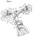
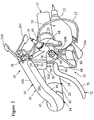
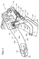
- A brake operating device for use with a handle bar having a first grip portion extending in a first direction and a second grip portion extending in a second direction which forms an angle with the first direction, comprising:a lever bracket for attachment to the handle bar and to a portion of a control wire; anda brake lever pivotally coupled to said lever bracket between a release position and a brake position, said brake lever includinga retaining portion forming a connection point for coupling one end of the control wire thereto,a first hand portion swingably mounted about a pivot axis and positioned adjacent the first grip portion of the handle bar to permit the rider's hand to grasp said first hand portion from the first grip portion of the handle bar, anda second hand portion swingably mounted about a pivot axis and positioned adjacent the second grip portion of the handle bar to permit the rider's hand to grasp said second hand portion from the second grip portion of the handle bar, said first and second hand portions of said brake lever having points of force which are spaced approximately 45° or less apart from each other as measured about their respective pivot axes in said release position of said brake lever.
- A brake operating device according to claim 1, whereinsaid pivot axes are coaxial and form an acute angle with the second grip portion of the handle bar.
- A brake operating device according to either preceding claim, further comprisinga spring coupled between said brake lever and said lever bracket for biasing said brake lever to a release position.
- A brake operating device according to any preceding claim, whereinsaid first and second hand portions are fixedly coupled together for simultaneous movement.
- A brake operating device according to any preceding claim, whereinsaid pivot axes being coaxial and said lever bracket has a pair of opposed side walls with a pivot pin extending therebetween and forming said pivot axes for pivotally receiving said brake lever thereon.
- A brake operating device according to any preceding claim, whereinsaid lever bracket includes a clamp for releasably coupling said lever bracket to one end of the handle bar.
- A brake operating device according to any preceding claim, whereinsaid lever bracket is integrally formed as a one-piece, unitary part of the first grip portion of the handle bar.
- A brake operating device according to any preceding claim, whereinsaid first hand portion lies on one side of said lever bracket and said second hand portion lies on the other side of said lever bracket.
- A brake operating device according to any preceding claim, whereinsaid points of force of said first and second hand portions of said brake lever are located within a range of 0° - 36° apart from each other as measured about their respective said pivot axes in said release position of said brake lever.
- A brake operating device according to Claim 9, whereinsaid points of force of said first and second hand portions of said brake lever are located within a range of 0° - 8° apart from each other as measured about their respective said pivot axes in said release position of said brake lever.
- A brake operating device according to any preceding claim, whereineach of said first and second hand portions has a free end.
- A brake operating device according to Claim 11, whereinsaid brake lever includes a connecting portion with a first end pivotally coupled to said lever bracket via a pivot pin and a second end coupled to each of said first and second hand portions.
- A brake operating device according to Claim 12, whereinsaid brake lever further includes a first arm portion interconnecting said first hand portion to said second end of said connecting portion and a second arm portion interconnecting said second hand portion to said second end of said connecting portion, said first hand portion being positioned on one side of said connecting portion and said second hand portion being positioned on the other side of said connecting portion.
- A brake operating device according to any of Claims 1 to 10, whereinsaid first hand portion has a first end pivotally coupled to said extension bar and a second end coupled to said second hand portion.
- A brake operating device according to any preceding claim, whereinsaid second hand portion extends substantially perpendicular to said first hand portion.
- An attachment assembly for attachment to one end of a handle bar, comprising:an extension bar having a first end with a clamp for coupling to the one end of the handle bar, a middle grip portion for receiving a rider's hand, and a second end positioned remotely from the handle bar; anda brake operating device fixedly coupled to said extension bar, said brake operating device includinga retaining portion forming a connection point for coupling one end of a control wire thereto,a first hand portion swingably mounted about a pivot point from a release position to a brake position and positioned adjacent said middle grip portion of said extension bar to permit the rider's hand to grasp said first hand portion from said middle grip portion of said extension bar, anda second hand portion swingably mounted about a pivot point from a release position to a brake position and positioned adjacent the handle bar coupled to said first end of said extension bar to permit the rider's hand to grasp said second hand portion from the handle bar.
- An attachment assembly according to claim 16, whereinsaid pivot points of said first and second hand portions are coaxially arranged about a first pivot axis.
- An attachment assembly according to claim 17, whereinsaid first and second hand portions have points of force which are spaced less than approximately 45° apart from each other as measured about said pivot axis in said release positions.
- An attachment assembly according to claim 17, whereinsaid first and second hand portions have points of force which are located within a range of 0° - 36° apart from each other as measured about said pivot point in said release positions.
- An attachment assembly according to any of Claims 17 to 19, whereinsaid pivot axis of said first and second hand portions forms an acute angle with the handle bar.
- An attachment assembly according to any of Claims 17 to 20, whereinsaid first and second hand portions are fixedly coupled together for simultaneous movement.
- An attachment assembly according to any of Claims 16 to 21, whereinsaid brake operating device includes a lever bracket integrally formed as a one-piece, unitary part of said extension bar with said first and second hand portions pivotally coupled thereto.
- An attachment assembly according to any of Claims 16 to 21, whereinsaid brake operating device includes a lever bracket with a clamp for coupling said first and second hand portions to said extension bar.
- An attachment assembly according to any of Claims 16 to 23, whereineach of said first and second hand portions has a free end.
- An attachment assembly according to any of Claims 16 to 24, whereinsaid first hand portion has a first end pivotally coupled to said extension bar and a second end coupled to said second hand portion.
- An attachment assembly according to any of Claims 16 to 25, whereinsaid second hand portion extends substantially perpendicular to said first hand portion.
- An attachment assembly according to any of Claims 16 to 26, whereinsaid extension bar has an upper gripping surface, a lower gripping surface, an outer gripping surface and an inner gripping surface, said inner gripping surface faces generally toward the handle bar attached to said clamp, said brake operating device extends outwardly from said inner gripping surface so that the rider's hand can grasp said upper, lower and outer gripping surfaces of said extension bar adjacent said brake operating device.
- A brake operating device for use with a handle bar having a first grip portion and a second grip portion, comprising:a lever bracket for attachment to the handle bar and to a portion of a control wire, said lever bracket having a pivot point with a pivot axis arranged substantially transverse to a longitudinal plane of said lever bracket; anda brake lever pivotally coupled to said lever bracket about said pivot point between a release position and a brake position, said brake lever includinga retaining portion forming a connection point for coupling one end of the control wire thereto,a first hand portion swingably mounted about said pivot point and lying on one side of said longitudinal plane of said lever bracket such that said first hand portion is located adjacent the first grip portion of the handle bar to permit the rider's hand to grasp said first hand portion from the first grip portion of the handle bar, anda second hand portion swingably mounted about said pivot point and lying on an opposed side of said longitudinal plane from said first hand portion such that said second hand portion is positioned adjacent the second grip portion of the handle bar to permit the rider's hand to grasp said second hand portion from the second grip portion of the handle bar.
- A brake operating device according to claim 28, further comprisinga spring coupled between said brake lever and said lever bracket for biasing said brake lever to a release position.
- A brake operating device according to either of Claims 28 or 29, whereinsaid first and second hand portions are fixedly coupled together for simultaneous movement.
- A brake operating device according to any of Claims 28 to 30, whereinsaid lever bracket has a pair of opposed side walls with a pivot pin extending therebetween for pivotally receiving said brake lever thereon.
- A brake operating device according to any of Claims 28 to 31, whereinsaid lever bracket includes a clamp for releasably coupling said lever bracket to one end of the handle bar.
- A brake operating device according to any of Claims 28 to 32, whereinsaid first and second hand portions of said brake lever have points of force which are spaced less than approximately 45° apart from each other as measured about said pivot point in said release position of said brake lever.
- A brake operating device according to any of Claims 28 to 32, whereinsaid first and second hand portions of said brake lever have points of force which are located within a range of 0° - 36° apart from each other as measured about said pivot point in said release position of said brake lever.
- A brake operating device according to any of Claims 28 to 32, whereinsaid first and second hand portions of said brake lever have points of force which are located within a range of 0° - 8° apart from each other as measured about said pivot point in said release position of said brake lever.
- A brake operating device according to Claim 28, whereinsaid brake lever has a connecting portion with a first end pivotally coupled to said lever bracket via a pivot and a second end coupled to said first and second arm portions of said first and second hand portions, respectively.
- A brake operating device according to Claim 36, whereinsaid connecting portion includes first and second connecting sections with said first arm portion being coupled to said first connecting section and said second arm portion being coupled to said second connecting section.
- A handle bar assembly for attachment to a vehicle, comprising:a cross bar having a center portion, a first end with a first grip portion located on one side of said center portion, and a second end with a second grip portion located on the other side of said center portion;a first bar end having a first end coupled to said first end of said cross bar so as to extend generally perpendicular to said cross bar, a middle grip portion for receiving a rider's hand, and a second end positioned remotely from said cross bar; anda first brake operating device fixedly coupled to said first bar end, said first brake operating device includinga first retaining portion forming a first connection point for coupling one end of a first control wire thereto,a first hand portion swingably mounted about a pivot point from a release position to a brake position and positioned adjacent said middle grip portion of said first bar end to permit the rider's hand to grasp said first hand portion from said middle grip portion of said first bar end, anda second hand portion swingably mounted about a pivot point from a release position to a brake position and positioned adjacent said first grip portion of said cross bar to permit the rider's hand to grasp said second hand portion from said first grip portion of said cross bar.
- A handle bar according to Claim 38, further comprising:a second bar end having a first end coupled to said second end of said cross bar so as to extend generally perpendicular to said cross bar, a middle grip portion for receiving a rider's hand, and a second end positioned remotely from said cross bar; anda second brake operating device fixedly coupled to said second bar end, said second brake operating device includinga second retaining portion forming a second connection point for coupling one end of a second control wire thereto,a third hand portion swingably mounted about a pivot point from a release position to a brake position and positioned adjacent said middle grip portion of said second bar end to permit the rider's hand to grasp said third hand portion from said middle grip portion of said second bar end, anda fourth hand portion swingably mounted about a pivot point from a release position to a brake position and positioned adjacent said second grip portion of said cross bar to permit the rider's hand to grasp said fourth hand portion from said second grip portion of said cross bar.
- A handle bar assembly according to claim 39, whereinsaid pivot points of said first and second hand portions are coaxially arranged about a first pivot axis, and said pivot points of said third and fourth hand portions are coaxially arranged about a second pivot axis.
- A handle bar according to claim 40, whereinsaid first and second hand portions have points of force which are spaced less than approximately 45° apart from each other as measured about said first pivot axis in their respective said release positions, and said third and fourth hand portions have points of force which are spaced less than approximately 45° apart from each other as measured about said second pivot axis in their respective said release positions.
- A handle bar assembly according to any of Claims 39 to 41, further comprisingat least one shift lever mounted on said first bar end and at least one shift lever mounted on said second bar end.
- A handle bar assembly according to any of Claims 39 to 42, whereinsaid first bar end includes a first clamp for releasably coupling said first bar end to said first end of said cross bar, and said second bar end includes a second clamp for releasably coupling said second bar end to said second end of said cross bar.
- A handle bar assembly according to any of Claims 39 to 43, whereinsaid first bar end has an upper gripping surface, a lower gripping surface, an outer gripping surface and an inner gripping surface, said inner gripping surface faces generally toward said center portion of said cross bar, said first brake operating device extends outwardly from said inner gripping surface so that the rider's hand can grasp said upper, lower and outer gripping surfaces of said first bar end adjacent said first brake operating device, andsaid second bar end has an upper gripping surface, a lower gripping surface, an outer gripping surface and an inner gripping surface, said inner gripping surface faces generally toward said center portion of said cross bar, said second brake operating device extends outwardly from said inner gripping surface of said second bar end so that the rider's hand can grasp said upper, lower and outer gripping surfaces of said second bar end adjacent said second brake operating device.
- A handle bar assembly according to any of Claims 39 to 44, whereinsaid first brake operating device includes a first lever bracket for pivotally coupling said first and second hand portions to said first bar end, said first hand portion is positioned on a first side of said first lever bracket and said second hand portion is positioned on a second side of said first lever bracket, andsaid second brake operating device includes a second lever bracket for pivotally coupling said third and fourth hand portions to said second bar end, said third hand portion is positioned on a first side of said second lever bracket and said fourth hand portion is positioned on a second side of said second lever bracket.
Applications Claiming Priority (2)
| Application Number | Priority Date | Filing Date | Title |
|---|---|---|---|
| US768897 | 1996-12-17 | ||
| US08/768,897 US5850761A (en) | 1996-12-17 | 1996-12-17 | Brake operating device for handle bar and bar ends |
Publications (3)
| Publication Number | Publication Date |
|---|---|
| EP0849150A2 true EP0849150A2 (en) | 1998-06-24 |
| EP0849150A3 EP0849150A3 (en) | 1999-12-15 |
| EP0849150B1 EP0849150B1 (en) | 2004-04-07 |
Family
ID=25083812
Family Applications (1)
| Application Number | Title | Priority Date | Filing Date |
|---|---|---|---|
| EP97309479A Revoked EP0849150B1 (en) | 1996-12-17 | 1997-11-25 | Brake operating device |
Country Status (5)
| Country | Link |
|---|---|
| US (1) | US5850761A (en) |
| EP (1) | EP0849150B1 (en) |
| CN (1) | CN1230344C (en) |
| DE (1) | DE69728506T2 (en) |
| TW (1) | TW427946B (en) |
Cited By (3)
| Publication number | Priority date | Publication date | Assignee | Title |
|---|---|---|---|---|
| WO2000029280A1 (en) * | 1998-11-12 | 2000-05-25 | At Design Inc. | Cycle handlebar actuator |
| EP1932754A3 (en) * | 2006-10-13 | 2008-07-02 | Shimano Inc. | Bicycle handlebar assembly and bicycle brake operating device |
| EP2468614A1 (en) * | 2010-12-03 | 2012-06-27 | Campagnolo S.r.l. | Actuation device for a control cable for a bicycle gearshift |
Families Citing this family (10)
| Publication number | Priority date | Publication date | Assignee | Title |
|---|---|---|---|---|
| JP3205709B2 (en) † | 1996-12-19 | 2001-09-04 | 株式会社シマノ | Sub-speed change operation device, main speed change operation device, and speed change operation system for bicycle |
| SE523428C2 (en) * | 2001-11-02 | 2004-04-20 | Electrolux Ab | Thumb-operated throttle |
| US20030230160A1 (en) * | 2002-03-20 | 2003-12-18 | Ritchey Designs, Inc. | Barend mounted twist shifter with integrated brake actuator for bicycle |
| WO2006050153A2 (en) * | 2004-10-30 | 2006-05-11 | Acenbrak Steven D | Ergonomic shifter for a bicycle |
| US20060185940A1 (en) * | 2005-02-18 | 2006-08-24 | Szu-Fang Tsai | Auxiliary handbrake operating device |
| US10239581B2 (en) | 2011-08-26 | 2019-03-26 | Gevenalle, Inc | Bicycle brake and shift lever assembly |
| FR2982837B1 (en) * | 2011-11-21 | 2014-05-09 | Decathlon Sa | BRAKE SYSTEM HAVING PARALLEL BRAKE LEVER AT THE HANDLE |
| FR3046594B1 (en) * | 2016-01-12 | 2018-02-09 | Decathlon | BRAKING DEVICE FOR A VEHICLE COMPRISING A HANDLEBAR AND A BRAKE CABLE |
| US10183724B2 (en) | 2016-11-22 | 2019-01-22 | Shimano Inc. | Bicycle hydraulic operating system |
| US20220355889A1 (en) * | 2021-05-05 | 2022-11-10 | Shimano Inc. | Operating device for human-powered vehicle |
Citations (5)
| Publication number | Priority date | Publication date | Assignee | Title |
|---|---|---|---|---|
| US3915028A (en) | 1973-07-18 | 1975-10-28 | Shimano Industrial Co | Cycle brake operating device |
| US4084449A (en) | 1975-08-01 | 1978-04-18 | Shimano Industrial Company Limited | Brake lever for a bicycle |
| US4304145A (en) | 1979-01-31 | 1981-12-08 | Shimano Industrial Company Limited | Brake operating device |
| US4543847A (en) | 1983-01-08 | 1985-10-01 | Shimano Industrial Company Limited | Brake operating device for a bicycle |
| US5299466A (en) | 1992-08-10 | 1994-04-05 | Kona U.S.A., Inc. | Brake lever extension |
Family Cites Families (18)
| Publication number | Priority date | Publication date | Assignee | Title |
|---|---|---|---|---|
| FR856265A (en) * | 1939-02-20 | 1940-06-10 | Metallurg Du Rhone Ets | Brake lever support handlebar connection |
| NL164991C (en) * | 1975-08-08 | 1981-02-16 | Philips Nv | WRAPPING CAPACITOR WITH PRESSURE PROTECTION. |
| JPS5320246A (en) * | 1976-08-09 | 1978-02-24 | Yoshigai Kikai Kinzoku Co Ltd | Brake actuator |
| JPS5464339A (en) * | 1977-10-27 | 1979-05-24 | Akihiro Yamamuro | Gid net lever |
| JPS5511965A (en) * | 1978-07-13 | 1980-01-28 | Akihiro Yamamuro | Brake lever for handlebar |
| US4245522A (en) * | 1979-06-13 | 1981-01-20 | Robinson Merritt A | Bicycle steering and control member |
| US4462267A (en) * | 1980-03-01 | 1984-07-31 | Shimano Industrial Company, Limited | Handlebar for a bicycle |
| US5211074A (en) * | 1989-11-22 | 1993-05-18 | Yoshigai Kikai Kinzoku Co., Ltd. | Handle device for bicycles |
| DE9105274U1 (en) * | 1991-04-29 | 1991-07-04 | K.W. Hochschorner Gmbh, 8033 Martinsried, De | |
| DE9211708U1 (en) * | 1992-08-31 | 1992-11-12 | Yann-Haur Industry Co., Ltd., Pu-Yen Hsiang, Changhua, Tw | |
| JP2597741Y2 (en) * | 1993-07-21 | 1999-07-12 | 株式会社シマノ | Bicycle brake lever device |
| US5392669A (en) * | 1993-08-20 | 1995-02-28 | Li; Jung-Hua | Brake lever for a handlebar of a bicycle |
| US5493933A (en) * | 1994-01-10 | 1996-02-27 | Kelly; Christopher J. | One piece shift lever mount adapter for a bicycle |
| JP2968445B2 (en) * | 1994-12-28 | 1999-10-25 | 株式会社シマノ | Interlocked gear shifting mechanism for bicycles |
| JP2968444B2 (en) * | 1994-12-28 | 1999-10-25 | 株式会社シマノ | Speed change mechanism for bicycle |
| DE69524191T3 (en) * | 1994-12-28 | 2008-01-24 | Shimano Inc., Sakai | Gearshift apparatus for a bicycle |
| US5775168A (en) * | 1996-02-14 | 1998-07-07 | Shimano, Inc. | Combined brake and shifting device |
| US5678455A (en) * | 1996-02-15 | 1997-10-21 | Shimano, Inc. | Bar-end shifting device |
-
1996
- 1996-12-17 US US08/768,897 patent/US5850761A/en not_active Expired - Lifetime
-
1997
- 1997-10-14 TW TW086115053A patent/TW427946B/en active
- 1997-10-30 CN CNB971224544A patent/CN1230344C/en not_active Expired - Fee Related
- 1997-11-25 EP EP97309479A patent/EP0849150B1/en not_active Revoked
- 1997-11-25 DE DE69728506T patent/DE69728506T2/en not_active Expired - Lifetime
Patent Citations (5)
| Publication number | Priority date | Publication date | Assignee | Title |
|---|---|---|---|---|
| US3915028A (en) | 1973-07-18 | 1975-10-28 | Shimano Industrial Co | Cycle brake operating device |
| US4084449A (en) | 1975-08-01 | 1978-04-18 | Shimano Industrial Company Limited | Brake lever for a bicycle |
| US4304145A (en) | 1979-01-31 | 1981-12-08 | Shimano Industrial Company Limited | Brake operating device |
| US4543847A (en) | 1983-01-08 | 1985-10-01 | Shimano Industrial Company Limited | Brake operating device for a bicycle |
| US5299466A (en) | 1992-08-10 | 1994-04-05 | Kona U.S.A., Inc. | Brake lever extension |
Cited By (7)
| Publication number | Priority date | Publication date | Assignee | Title |
|---|---|---|---|---|
| WO2000029280A1 (en) * | 1998-11-12 | 2000-05-25 | At Design Inc. | Cycle handlebar actuator |
| EP1932754A3 (en) * | 2006-10-13 | 2008-07-02 | Shimano Inc. | Bicycle handlebar assembly and bicycle brake operating device |
| US7874229B2 (en) | 2006-10-13 | 2011-01-25 | Shimano Inc. | Bicycle handlebar assembly and bicycle brake/derailleur operating unit |
| EP2468614A1 (en) * | 2010-12-03 | 2012-06-27 | Campagnolo S.r.l. | Actuation device for a control cable for a bicycle gearshift |
| CN102556279A (en) * | 2010-12-03 | 2012-07-11 | 坎培诺洛有限公司 | Actuation device for a control cable for a bicycle gearshift |
| CN102556279B (en) * | 2010-12-03 | 2015-11-18 | 坎培诺洛有限公司 | For the bicycle gearshift actuating device controlling cable |
| US9266581B2 (en) | 2010-12-03 | 2016-02-23 | Campagnolo S.R.L. | Actuation device for a control cable for a bicycle gearshift |
Also Published As
| Publication number | Publication date |
|---|---|
| DE69728506D1 (en) | 2004-05-13 |
| DE69728506T2 (en) | 2005-03-24 |
| CN1185395A (en) | 1998-06-24 |
| EP0849150B1 (en) | 2004-04-07 |
| CN1230344C (en) | 2005-12-07 |
| US5850761A (en) | 1998-12-22 |
| TW427946B (en) | 2001-04-01 |
| EP0849150A3 (en) | 1999-12-15 |
Similar Documents
| Publication | Publication Date | Title |
|---|---|---|
| US10308309B2 (en) | Control device for a bicycle and bicycle comprising such a device | |
| US6941834B2 (en) | Bicycle component operating device | |
| EP0849150B1 (en) | Brake operating device | |
| EP0035359A2 (en) | Cycle handlebar system | |
| US20080210041A1 (en) | Control device for a bicycle and bicycle comprising such a device | |
| US4445396A (en) | Handlebar for a bicycle | |
| EP0047637A1 (en) | Cycle control device | |
| EP1877300B1 (en) | Handlebar extension | |
| US5743284A (en) | Cantilever brake with pad attitude control | |
| US20030226721A1 (en) | Cable joining system for cycles | |
| US5050444A (en) | Bicycle brake lever assembly | |
| EP0035372A2 (en) | Cycle handlebars | |
| US4901595A (en) | Auxiliary brake control assembly for bicycle | |
| US20040244526A1 (en) | Bicycle handlebar | |
| US11420705B2 (en) | Handlebar | |
| EP1698551A2 (en) | Bicycle control apparatus | |
| US9010788B2 (en) | Bicycle handlebar | |
| US6805023B2 (en) | Integrated rider control system for handlebar steered vehicles | |
| EP3992070A1 (en) | Handlebar | |
| US20230415841A1 (en) | Handlebar with a mounting arrangement | |
| JP2543789B2 (en) | Bicycle, handlebar and adapter kit | |
| CN115230860A (en) | Operating device for a human powered vehicle | |
| JPH0537672U (en) | Bicycle handle | |
| WO2006098707A1 (en) | Cable joining system for cycles |
Legal Events
| Date | Code | Title | Description |
|---|---|---|---|
| PUAI | Public reference made under article 153(3) epc to a published international application that has entered the european phase |
Free format text: ORIGINAL CODE: 0009012 |
|
| 17P | Request for examination filed |
Effective date: 19971210 |
|
| AK | Designated contracting states |
Kind code of ref document: A2 Designated state(s): DE FR GB IT |
|
| AX | Request for extension of the european patent |
Free format text: AL;LT;LV;MK;RO;SI |
|
| PUAL | Search report despatched |
Free format text: ORIGINAL CODE: 0009013 |
|
| AK | Designated contracting states |
Kind code of ref document: A3 Designated state(s): AT BE CH DE DK ES FI FR GB GR IE IT LI LU MC NL PT SE |
|
| AX | Request for extension of the european patent |
Free format text: AL;LT;LV;MK;RO;SI |
|
| AKX | Designation fees paid |
Free format text: DE FR GB IT |
|
| 17Q | First examination report despatched |
Effective date: 20021004 |
|
| GRAP | Despatch of communication of intention to grant a patent |
Free format text: ORIGINAL CODE: EPIDOSNIGR1 |
|
| GRAS | Grant fee paid |
Free format text: ORIGINAL CODE: EPIDOSNIGR3 |
|
| GRAA | (expected) grant |
Free format text: ORIGINAL CODE: 0009210 |
|
| AK | Designated contracting states |
Kind code of ref document: B1 Designated state(s): DE FR GB IT |
|
| REG | Reference to a national code |
Ref country code: GB Ref legal event code: FG4D |
|
| REF | Corresponds to: |
Ref document number: 69728506 Country of ref document: DE Date of ref document: 20040513 Kind code of ref document: P |
|
| PLBI | Opposition filed |
Free format text: ORIGINAL CODE: 0009260 |
|
| ET | Fr: translation filed | ||
| PLAQ | Examination of admissibility of opposition: information related to despatch of communication + time limit deleted |
Free format text: ORIGINAL CODE: EPIDOSDOPE2 |
|
| PLAR | Examination of admissibility of opposition: information related to receipt of reply deleted |
Free format text: ORIGINAL CODE: EPIDOSDOPE4 |
|
| PLBQ | Unpublished change to opponent data |
Free format text: ORIGINAL CODE: EPIDOS OPPO |
|
| PLAB | Opposition data, opponent's data or that of the opponent's representative modified |
Free format text: ORIGINAL CODE: 0009299OPPO |
|
| 26 | Opposition filed |
Opponent name: SRAM DEUTSCHLAND GMBH Effective date: 20041223 |
|
| PLAX | Notice of opposition and request to file observation + time limit sent |
Free format text: ORIGINAL CODE: EPIDOSNOBS2 |
|
| R26 | Opposition filed (corrected) |
Opponent name: SRAM DEUTSCHLAND GMBH Effective date: 20041223 |
|
| PLBB | Reply of patent proprietor to notice(s) of opposition received |
Free format text: ORIGINAL CODE: EPIDOSNOBS3 |
|
| PLAB | Opposition data, opponent's data or that of the opponent's representative modified |
Free format text: ORIGINAL CODE: 0009299OPPO |
|
| PGFP | Annual fee paid to national office [announced via postgrant information from national office to epo] |
Ref country code: GB Payment date: 20051123 Year of fee payment: 9 |
|
| RAP2 | Party data changed (patent owner data changed or rights of a patent transferred) |
Owner name: SHIMANO INC. |
|
| GBPC | Gb: european patent ceased through non-payment of renewal fee |
Effective date: 20061125 |
|
| PG25 | Lapsed in a contracting state [announced via postgrant information from national office to epo] |
Ref country code: GB Free format text: LAPSE BECAUSE OF NON-PAYMENT OF DUE FEES Effective date: 20061125 |
|
| PGFP | Annual fee paid to national office [announced via postgrant information from national office to epo] |
Ref country code: IT Payment date: 20081127 Year of fee payment: 12 |
|
| PGFP | Annual fee paid to national office [announced via postgrant information from national office to epo] |
Ref country code: FR Payment date: 20081112 Year of fee payment: 12 |
|
| REG | Reference to a national code |
Ref country code: FR Ref legal event code: ST Effective date: 20100730 |
|
| PG25 | Lapsed in a contracting state [announced via postgrant information from national office to epo] |
Ref country code: FR Free format text: LAPSE BECAUSE OF NON-PAYMENT OF DUE FEES Effective date: 20091130 |
|
| REG | Reference to a national code |
Ref country code: DE Ref legal event code: R103 Ref document number: 69728506 Country of ref document: DE Ref country code: DE Ref legal event code: R064 Ref document number: 69728506 Country of ref document: DE |
|
| RDAF | Communication despatched that patent is revoked |
Free format text: ORIGINAL CODE: EPIDOSNREV1 |
|
| PGFP | Annual fee paid to national office [announced via postgrant information from national office to epo] |
Ref country code: DE Payment date: 20101117 Year of fee payment: 14 |
|
| PG25 | Lapsed in a contracting state [announced via postgrant information from national office to epo] |
Ref country code: IT Free format text: LAPSE BECAUSE OF NON-PAYMENT OF DUE FEES Effective date: 20091125 |
|
| RDAG | Patent revoked |
Free format text: ORIGINAL CODE: 0009271 |
|
| STAA | Information on the status of an ep patent application or granted ep patent |
Free format text: STATUS: PATENT REVOKED |
|
| 27W | Patent revoked |
Effective date: 20110201 |
|
| REG | Reference to a national code |
Ref country code: DE Ref legal event code: R107 Ref document number: 69728506 Country of ref document: DE Effective date: 20110901 |