EP0849002B1 - Ausgabevorrichtung für in Kartuschen bereitgestellte,fliessfähige Medien - Google Patents
Ausgabevorrichtung für in Kartuschen bereitgestellte,fliessfähige Medien Download PDFInfo
- Publication number
- EP0849002B1 EP0849002B1 EP97121849A EP97121849A EP0849002B1 EP 0849002 B1 EP0849002 B1 EP 0849002B1 EP 97121849 A EP97121849 A EP 97121849A EP 97121849 A EP97121849 A EP 97121849A EP 0849002 B1 EP0849002 B1 EP 0849002B1
- Authority
- EP
- European Patent Office
- Prior art keywords
- pressure
- dispensing device
- dispensing
- compressor
- piston
- Prior art date
- Legal status (The legal status is an assumption and is not a legal conclusion. Google has not performed a legal analysis and makes no representation as to the accuracy of the status listed.)
- Expired - Lifetime
Links
- 239000012530 fluid Substances 0.000 title 1
- 230000009969 flowable effect Effects 0.000 claims description 7
- 230000006835 compression Effects 0.000 description 4
- 238000007906 compression Methods 0.000 description 4
- 230000005540 biological transmission Effects 0.000 description 2
- 230000008878 coupling Effects 0.000 description 2
- 238000010168 coupling process Methods 0.000 description 2
- 238000005859 coupling reaction Methods 0.000 description 2
- 238000001125 extrusion Methods 0.000 description 2
- 239000000463 material Substances 0.000 description 2
- 239000000853 adhesive Substances 0.000 description 1
- 230000001070 adhesive effect Effects 0.000 description 1
- 238000010276 construction Methods 0.000 description 1
- 238000006073 displacement reaction Methods 0.000 description 1
- 239000003925 fat Substances 0.000 description 1
- 238000012423 maintenance Methods 0.000 description 1
- 238000004519 manufacturing process Methods 0.000 description 1
- 235000011837 pasties Nutrition 0.000 description 1
- 229920002379 silicone rubber Polymers 0.000 description 1
- 239000004945 silicone rubber Substances 0.000 description 1
- 238000001228 spectrum Methods 0.000 description 1
Images


Classifications
-
- B—PERFORMING OPERATIONS; TRANSPORTING
- B05—SPRAYING OR ATOMISING IN GENERAL; APPLYING FLUENT MATERIALS TO SURFACES, IN GENERAL
- B05C—APPARATUS FOR APPLYING FLUENT MATERIALS TO SURFACES, IN GENERAL
- B05C17/00—Hand tools or apparatus using hand held tools, for applying liquids or other fluent materials to, for spreading applied liquids or other fluent materials on, or for partially removing applied liquids or other fluent materials from, surfaces
- B05C17/005—Hand tools or apparatus using hand held tools, for applying liquids or other fluent materials to, for spreading applied liquids or other fluent materials on, or for partially removing applied liquids or other fluent materials from, surfaces for discharging material from a reservoir or container located in or on the hand tool through an outlet orifice by pressure without using surface contacting members like pads or brushes
- B05C17/00586—Means, generally located near the nozzle, for piercing or perforating the front part of a cartridge
-
- B—PERFORMING OPERATIONS; TRANSPORTING
- B05—SPRAYING OR ATOMISING IN GENERAL; APPLYING FLUENT MATERIALS TO SURFACES, IN GENERAL
- B05C—APPARATUS FOR APPLYING FLUENT MATERIALS TO SURFACES, IN GENERAL
- B05C17/00—Hand tools or apparatus using hand held tools, for applying liquids or other fluent materials to, for spreading applied liquids or other fluent materials on, or for partially removing applied liquids or other fluent materials from, surfaces
- B05C17/005—Hand tools or apparatus using hand held tools, for applying liquids or other fluent materials to, for spreading applied liquids or other fluent materials on, or for partially removing applied liquids or other fluent materials from, surfaces for discharging material from a reservoir or container located in or on the hand tool through an outlet orifice by pressure without using surface contacting members like pads or brushes
- B05C17/00569—Hand tools or apparatus using hand held tools, for applying liquids or other fluent materials to, for spreading applied liquids or other fluent materials on, or for partially removing applied liquids or other fluent materials from, surfaces for discharging material from a reservoir or container located in or on the hand tool through an outlet orifice by pressure without using surface contacting members like pads or brushes with a pump in the hand tool
-
- B—PERFORMING OPERATIONS; TRANSPORTING
- B05—SPRAYING OR ATOMISING IN GENERAL; APPLYING FLUENT MATERIALS TO SURFACES, IN GENERAL
- B05C—APPARATUS FOR APPLYING FLUENT MATERIALS TO SURFACES, IN GENERAL
- B05C17/00—Hand tools or apparatus using hand held tools, for applying liquids or other fluent materials to, for spreading applied liquids or other fluent materials on, or for partially removing applied liquids or other fluent materials from, surfaces
- B05C17/005—Hand tools or apparatus using hand held tools, for applying liquids or other fluent materials to, for spreading applied liquids or other fluent materials on, or for partially removing applied liquids or other fluent materials from, surfaces for discharging material from a reservoir or container located in or on the hand tool through an outlet orifice by pressure without using surface contacting members like pads or brushes
- B05C17/01—Hand tools or apparatus using hand held tools, for applying liquids or other fluent materials to, for spreading applied liquids or other fluent materials on, or for partially removing applied liquids or other fluent materials from, surfaces for discharging material from a reservoir or container located in or on the hand tool through an outlet orifice by pressure without using surface contacting members like pads or brushes with manually mechanically or electrically actuated piston or the like
- B05C17/0103—Hand tools or apparatus using hand held tools, for applying liquids or other fluent materials to, for spreading applied liquids or other fluent materials on, or for partially removing applied liquids or other fluent materials from, surfaces for discharging material from a reservoir or container located in or on the hand tool through an outlet orifice by pressure without using surface contacting members like pads or brushes with manually mechanically or electrically actuated piston or the like with electrically actuated piston or the like
-
- B—PERFORMING OPERATIONS; TRANSPORTING
- B65—CONVEYING; PACKING; STORING; HANDLING THIN OR FILAMENTARY MATERIAL
- B65D—CONTAINERS FOR STORAGE OR TRANSPORT OF ARTICLES OR MATERIALS, e.g. BAGS, BARRELS, BOTTLES, BOXES, CANS, CARTONS, CRATES, DRUMS, JARS, TANKS, HOPPERS, FORWARDING CONTAINERS; ACCESSORIES, CLOSURES, OR FITTINGS THEREFOR; PACKAGING ELEMENTS; PACKAGES
- B65D83/00—Containers or packages with special means for dispensing contents
- B65D83/771—Containers or packages with special means for dispensing contents for dispensing fluent contents by means of a flexible bag or a deformable membrane or diaphragm
- B65D83/7713—Containers or packages with special means for dispensing contents for dispensing fluent contents by means of a flexible bag or a deformable membrane or diaphragm the contents of a flexible bag being expelled by a piston, or a movable bottom or partition provided in the container or the package
Definitions
- the invention relates to a dispensing device for cartridges provided flowable media, with at least one substantially cylindrical receiving area for a cartridge, at least one Output area for the flowable medium at an end area of the Recording area and a device for generating a Normal pressure deviating pressure at an end region of the Recording area.
- Cartridges for flowable media are known per se. These are flowable containers for storage, transport and dispensing Media. In the first place, it is pasty media such as Silicone rubber and the like, which, for example, in the area of Construction industry. But it is also known, adhesives, fats or fill other media into cartridges.
- cartridges are known. In one case it is an inherently rigid, tubular shell with a closed End area, which is designed as an extrusion area, and one in essential piston-like extrusion at the other end.
- tubular bag Another type of cartridge is the so-called tubular bag, the is exclusively flexible. This will be in special Dispensers used which have a tubular receiving area exhibit. Here the tubular bag is opened at one end and usually squeezed by pressure from the other end.
- cartridges are known in recent times, which have a flexible shell, an express area arranged thereon and one arranged thereon have pressure-receiving end region.
- Dispensing devices of the generic type are known per se.
- a Pressure generating device On cylindrical receiving area, depending on the type of cartridge, tubular or partially cylindrical, has an output area and a Pressure generating device.
- This can be a pressure piston, for example, with which by a lever movement a negative pressure or an excess pressure is generated within the cylindrical receiving area.
- EP 0250 890 Reiner Chemische Fabrik GmbH & Co shows such an output device.
- a previously known device has such a pump piston, the one Negative pressure at the squeezing end of a cartridge, d. H. at the output area of the cylindrical recording area created and the flowable medium after Opening the cartridge sucks it out.
- the present invention has the object of developing an output device of the generic type such that a high degree of emptying, on the other hand ensures an inserted cartridge of a hand and a predetermined compression of the cartridge, wherein the dispenser economical to manufacture and easy to use and robust is constructed.
- the invention proposes that an output line is formed in the output area with a valve element loaded in the closed position, the device for generating the pressure is a compressor unit for generating an overpressure in the cylindrical receiving area, and the output device has a handle the movement of which both the compressor unit and the valve element can be actuated directly or indirectly.
- the design according to the invention makes it simple Output device provided, an output line in the output area with a valve element loaded in the closed position.
- the device for generating pressure by a compressor unit formed, which in the receiving area, which is preferably cylindrical, a Overpressure generated.
- a handle on the dispenser arranged, the movement of which both the compressor unit and directly or indirectly actuated the valve element. The movement of the handle leads on the one hand to a movement of the compressor unit, causing the air overpressure is generated by this, which preferably via lines in the cylindrical receiving area is guided, and at the same time moves that Valve element.
- both Elements can also be mechanically decoupled, so that the valve element is controlled by a pressure, for example an overpressure in the cylindrical recording area, an overpressure of the output Medium, an air negative pressure, generated by an intake stroke Compressor unit, magnetic, electric and the like.
- a pressure for example an overpressure in the cylindrical recording area, an overpressure of the output Medium, an air negative pressure, generated by an intake stroke Compressor unit, magnetic, electric and the like.
- the output device according to the invention becomes extremely flexible, easy to use and can be manufactured extremely robust, so that an effective Function is guaranteed at all times.
- the invention proposes that the valve element Slider element is, which according to a further advantageous proposal of the invention is movable transversely to a longitudinal axis of the receiving area.
- This arrangement causes a transverse displacement of the slide Open an output line.
- plug-like valve elements realizable, one with a longitudinal axis of the receiving area Seal the aligned hole.
- the compressor is advantageously a piston compressor, in the simplest So in the case of a simple translatory piston in a cylinder, the a compression stroke on one side and an intake stroke in the other direction performs.
- the piston compressor is also advantageously in the Output area arranged for easy coupling of compressor and Perform valve element.
- the piston compressor transverse to Longitudinal axis of the receiving area movable, so that for example mechanical unit can be formed from the valve element and piston. This reduces the number of components, the assembly and the Maintenance effort.
- the handle is advantageously a pivotably arranged lever, the axis lying transversely to the longitudinal axis of the receiving area and swung here and with little effort through the Lever translation corresponding movements of the movable elements in the Can generate output area.
- a pressure relief valve is additionally in the output line arranged to the valve element.
- This pressure relief valve causes first by moving the handle and thus moving the A minimum pressure must be generated in the intake area before the compressor the medium that regularly passes through the valve element, also that Pressure relief valve can happen.
- a second device for Generation of a pressure deviating from normal pressure is provided with the one at the other end in the opposite direction from Normal pressure deviating pressure can be generated.
- the aspect of the invention thus boils down to the fact that when on Output area of the recording area a negative pressure is generated, an excess pressure is additionally generated at the opposite end.
- the adjustability or controllability of the pressure conditions becomes automatic causes that on the one hand the residual quantity emptying can be controlled, on the other hand, the material behavior of the inserted cartridge.
- the second Device is a piston element.
- This preferably produces one of the Atmospheric pressure deviating from normal pressure.
- the pressure generating device be a Double piston element is.
- Such a double piston element can Movement in one direction at a cylinder end a negative pressure when Move an overpressure in the other direction at the other end of the cylinder generate, for which only an appropriate cable routing is required.
- the double piston can preferably be actuated by levers, whereby a single or two movable levers can be used.
- the one from normal pressure deviating pressure is advantageously an air vacuum or a Atmospheric pressure.
- the lines can either be in the lever itself or in a side wall of the recording area.
- the line can also stand Line be arranged in the interior of the receiving area.
- Essential The function of the lines is to send the air pressure generated by the compressor to the end of the dispenser opposite the dispensing area of the dispenser To guide the recording area in order to put as much pressure on the To guide the back of the cartridge.
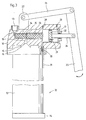
- the device shown in FIG. 1 is an output device 1 with a Receiving tube 2, in which a cartridge known per se (not shown) can be used.
- a discharge opening 3 is formed at one end, at the other end a lid 4 can be placed.
- a piston (not shown) 5 is inserted on the output side by means of which can be carried out via the gear 7 and the lever lifting movements are.
- a cartridge inserted into the receiving tube 2 is either open connected to the output area or, as shown Embodiment, opened by the opening device 6.
- the piston has a compression stroke and an intake stroke.
- the piston in one case on the side of the Output opening 3 a negative pressure, in the other case on the side of the Cover 4 generates an overpressure.
- the lever 9 is fixed and with a line 10 provided for pressure control.
- the printing can also be done differently, so that both Lever are movable.
- the gear design is without influence on that Spectrum of the present invention.
- the dispensing device 11 comprises a receiving tube 12 for Recording a cartridge, not shown, an output opening 13 for Dispensing the medium in the cartridge and a cover 14 for closing the receiving tube at the rear 2.
- the connection unit 15 comprises tip-shaped projections 16 for piercing the cartridge.
- the Output area 18 is a separate component and has one Output line 19, in which a valve for by a slide 20 Opening and closing the output line is arranged.
- a pressure relief valve 21 is arranged in the output line 19.
- the slide 20 is connected to the piston 22 via a mechanical connection 25 of the compressor 17 connected.
- the piston 22 is by means of the movement of the Lever 23 moves back and forth translationally via the gear linkage 24.
- the lever 23 is in turn on the counter bearing 27 by means of the counter bearing rod 26 arranged.
- the Overflow valve 29 air tracked.
- Corresponding optionally usable Valves 28 are also used for pressure control.
- the line 31 is outside next to the Receiving tube 12 arranged, but it can also in the wall or, at either a non-cylindrical pick-up tube or a pick-up tube oversize run inside the receiving tube. Also are Hose guides as in the embodiment shown in Fig. 1 possible.
- FIG. 3 An alternative embodiment is shown in FIG. 3. So much for there elements shown correspond to the elements shown in FIG. 2, the same reference numerals have been used.
- the device is the same Way constructed in Fig. 2.
- the key difference present device lies in the design of the valve in the Output line 19.
- This valve is in the embodiment shown as Double piston formed, wherein a suction piston 33 with a pressure piston 34 is firmly connected.
- An annular groove 35 is formed at the connection point.
- the function of the device is such that during a suction stroke of the piston 22, i.e. in the image plane of a movement to the right, in front of it Chamber is generated a negative pressure through which the suction piston 33rd is also moved to the right.
- the suction piston Since the suction piston compared to the Pressure piston 34 has a larger diameter, so next to the annular groove 35 results in an enlarged piston end face, the suction piston produces one Negative pressure, through which the medium in the lower area of the Output line 19 is sucked, which is the pressure promotion generated by the Overpressure of the piston 22, supported.
- the suction piston 33 With a pressure stroke of the piston 22, So seen in the image plane to the left, the suction piston 33 through mechanical contact also moves to the left and the pressure piston 34 presses the output line 19 and the discharge opening 13 in front of the Medium located in the piston.
Landscapes
- Engineering & Computer Science (AREA)
- Mechanical Engineering (AREA)
- Compressors, Vaccum Pumps And Other Relevant Systems (AREA)
- Coating Apparatus (AREA)
- Nozzles (AREA)
- Feeding And Controlling Fuel (AREA)
Description
- Fig. 1
- eine schematische Darstellung eines Ausführungsbeispiels für eine Ausgabevorrichtung,
- Fig. 2
- eine schematische Darstellung eines weiteren Ausführungsbeispiels für eine Ausgabevorrichtung, und
- Fig. 3
- eine schematische Darstellung eines weiteren Ausführungsbeispiels für eine Ausgabevorrichtung.
- 1
- Ausgabevorrichtung
- 2
- Aufnahmerohr
- 3
- Ausgabeöffnung
- 4
- Deckel
- 5
- Kolbenbereich
- 6
- Öffnungsvorrichtung
- 7
- Getriebe
- 8
- Hebel
- 9
- Hebel
- 10
- Leitung
- 11
- Ausgabevorrichtung
- 12
- Aufnahmerohr
- 13
- Ausgabeöffnung
- 14
- Deckel
- 15
- Anschlußeinheit
- 16
- Spitze
- 17
- Verdichter
- 18
- Ausgabebereich
- 19
- Ausgabeleitung
- 20
- Schieber
- 21
- Überdruckventil
- 22
- Kolben
- 23
- Hebel
- 24
- Getriebe
- 25
- Verbindung
- 26
- Gegenlagerstange
- 27
- Gegenlager
- 28
- Ventil
- 29
- Überströmventil
- 30
- Druckventil
- 31
- Leitung
- 32
- Ausgabevorrichtung
- 33
- Saugkolben
- 34
- Druckkolben
- 35
- Ringnut
Claims (14)
- Ausgabevorrichtung für in Kartuschen bereitgestellte fließfähige Medien, mit wenigstens einem im wesentlichen zylindrischen Aufnahmebereich für eine Kartusche, wenigstens einem Ausgabebereich für das fließfähige Medium an einem Endbereich des Aufnahmebereiches und einer Vorrichtung zur Erzeugung eines vom Normaldruck abweichenden Druckes an einem Endbereich des Aufnahmebereiches,
wobei,
im Ausgabebereich (18) eine Ausgabeleitung (19) mit einem Ventilelement (20) ausgebildet ist, die Vorrichtung zur Erzeugung des Druckes eine Verdichtereinheit (22) zur Erzeugung eines Überdruckes im zylindrischen Aufnahmebereich ist, und die Ausgabevorrichtung eine Handhabe (23) aufweist, durch deren Bewegung sowohl die Verdichtereinheit (22) als auch direkt oder indirekt das Ventilelement (20) betätigbar sind. - Ausgabevorrichtung nach Anspruch 1, dadurch gekennzeichnet, daß das Ventilelement ein Schieberelement ist.
- Ausgabevorrichtung nach Anspruch 2, dadurch gekennzeichnet, daß das Schieberelement quer zu einer Längsachse des Aufnahmebereiches bewegbar ist.
- Ausgabevorrichtung nach einem der vorhergehenden Ansprüche, dadurch gekennzeichnet, daß der Verdichter ein Kolbenkompressor ist.
- Ausgabevorrichtung nach einem der vorhergehenden Ansprüche, dadurch gekennzeichnet, daß der Verdichter im Ausgabebereich angeordnet ist.
- Vorrichtung nach einem der Ansprüche 4 oder 5, dadurch gekennzeichnet, daß der Verdichter quer zu einer Längsachse des Aufnahmebereiches bewegbar ist.
- Ausgabevorrichtung nach einem der vorhergehenden Ansprüche, dadurch gekennzeichnet, daß das Ventilelement und der Verdichter hintereinanderliegend angeordnet sind.
- Ausgabevorrichtung nach einem der vorhergehenden Ansprüche, dadurch gekennzeichnet, daß die Handhabe ein Hebel ist.
- Ausgabevorrichtung nach einem der vorhergehenden Ansprüche, dadurch gekennzeichnet, daß diese ein auf die Ausgabe wirkendes Überdruckventil aufweist.
- Ausgabevorrichtung nach einem der vorhergehenden Ansprüche, dadurch gekennzeichnet, daß eine zweite Vorrichtung zur Erzeugung eines vom Normaldruck abweichenden Druckes vorgesehen ist, mit der an dem anderen Endbereich ein in entgegengesetzter Richtung vom Normaldruck abweichender Druck erzeugbar ist.
- Vorrichtung nach Anspruch 10, dadurch gekennzeichnet, daß beide Druck erzeugenden Vorrichtungen in einem Doppelkolbenelement integriert sind.
- Ausgabevorrichtung nach einem der vorhergehenden Ansprüche, dadurch gekennzeichnet, daß zur Druckführung Leitungen ausgebildet sind.
- Ausgabevorrichtung nach Anspruch 12, dadurch gekennzeichnet, daß eine der Leitungen in einem der Hebel angeordnet ist.
- Ausgabevorrichtung nach Anspruch 12, dadurch gekennzeichnet, daß eine der Leitungen in einer Seitenwandung des Aufnahmebereiches ausgebildet ist.
Applications Claiming Priority (2)
| Application Number | Priority Date | Filing Date | Title |
|---|---|---|---|
| DE29622175U | 1996-12-20 | ||
| DE29622175U DE29622175U1 (de) | 1996-12-20 | 1996-12-20 | Ausgabevorrichtung für in Kartuschen bereitgestellte fließfähige Medien |
Publications (3)
| Publication Number | Publication Date |
|---|---|
| EP0849002A2 EP0849002A2 (de) | 1998-06-24 |
| EP0849002A3 EP0849002A3 (de) | 1999-05-12 |
| EP0849002B1 true EP0849002B1 (de) | 2001-08-16 |
Family
ID=8033620
Family Applications (1)
| Application Number | Title | Priority Date | Filing Date |
|---|---|---|---|
| EP97121849A Expired - Lifetime EP0849002B1 (de) | 1996-12-20 | 1997-12-11 | Ausgabevorrichtung für in Kartuschen bereitgestellte,fliessfähige Medien |
Country Status (2)
| Country | Link |
|---|---|
| EP (1) | EP0849002B1 (de) |
| DE (2) | DE29622175U1 (de) |
Families Citing this family (1)
| Publication number | Priority date | Publication date | Assignee | Title |
|---|---|---|---|---|
| ES2180944T3 (es) * | 1996-03-02 | 2003-02-16 | Frank Forstmann | Cartucho para medios fluidos. |
Family Cites Families (7)
| Publication number | Priority date | Publication date | Assignee | Title |
|---|---|---|---|---|
| US3353537A (en) * | 1965-08-11 | 1967-11-21 | George W Knox | Automatic multi-dosage inoculating instrument |
| DE3440893A1 (de) * | 1984-11-09 | 1986-05-22 | Reiner Chemische Fabrik GmbH & Co, 6751 Weilerbach | Handhebelpresse zum verpressen von viskosen massen |
| DE3444042A1 (de) * | 1984-12-03 | 1986-06-05 | Pressol Schmiergeräte GmbH, 8500 Nürnberg | Schmierpresse mit hochdruckraum |
| DE8616361U1 (de) * | 1986-06-19 | 1986-08-14 | Reiner Chemische Fabrik GmbH & Co, 6751 Weilerbach | Handhebelpresse zum Verpressen von viskosen Massen |
| DE8909425U1 (de) * | 1989-08-04 | 1989-10-05 | Schneider, Friedhelm, 5226 Reichshof | Kombinierte Dosierpistole für Hand- oder Druckluftbetrieb wahlweise verwendbar für Kartuschen oder Beutelpackungen |
| DE4422459A1 (de) * | 1994-06-28 | 1996-01-04 | Hydraulik Und Druckluft Servic | Ausdrückvorrichtung für Doppelkartusche |
| CN1062346C (zh) * | 1996-06-03 | 2001-02-21 | 程豹 | 一种采用密封油桶自吸油脂式高效注油枪 |
-
1996
- 1996-12-20 DE DE29622175U patent/DE29622175U1/de not_active Expired - Lifetime
-
1997
- 1997-12-11 DE DE59704291T patent/DE59704291D1/de not_active Expired - Fee Related
- 1997-12-11 EP EP97121849A patent/EP0849002B1/de not_active Expired - Lifetime
Also Published As
| Publication number | Publication date |
|---|---|
| DE59704291D1 (de) | 2001-09-20 |
| DE29622175U1 (de) | 1997-02-13 |
| EP0849002A2 (de) | 1998-06-24 |
| EP0849002A3 (de) | 1999-05-12 |
Similar Documents
| Publication | Publication Date | Title |
|---|---|---|
| EP0497256B1 (de) | Austragvorrichtung für Medien | |
| DE68903665T2 (de) | Balg-pipette und ihre verwendung. | |
| DE69511466T2 (de) | Spender zum Spenden von unter Druck zerstäubten Fluiden, mit einem durch das unter Druck stehenden Fluids betätigten Verschlussstück | |
| DE10231751B4 (de) | Saug-Druck-Pumpe zum Ausspritzen eines Produkts aus einem Behältnis | |
| EP0968386B1 (de) | Presse zum verpressen von schmierfetten sowie hierbei verwandete kartusche | |
| DE2920882C2 (de) | Ventilanordnung an einem Druckgasbehälter, die dessen Entleerung auf einen Druck unterhalb eines Restdruckes verhindert sowie dessen Füllung zuläßt. | |
| DE102009053134A1 (de) | Ballenpresse | |
| DE8590051U1 (de) | Vorrichtung zum Komprimieren von Material | |
| EP0849002B1 (de) | Ausgabevorrichtung für in Kartuschen bereitgestellte,fliessfähige Medien | |
| DE69600515T2 (de) | Flüssigkeitsspender für zwei Produkten | |
| DE102012009207A1 (de) | Füllelement | |
| DE102004024471B3 (de) | Pumpe zur Entnahme von Flüssigkeit oder pastöser Masse, entsprechender Spendeapparat und entsprechendes Verfahren | |
| DE2711208A1 (de) | Verfahren und vorrichtung zum dosieren und abfuellen insbesondere hochviskoser medien | |
| DE3113491A1 (de) | Verpackungsbehaelter fuer dickfluessige und pastoese fuellgitter | |
| DE102011004967A1 (de) | Auspressgerät | |
| DE69208084T2 (de) | Selbstdichtender Verschluss für einen flexiblen Behälter | |
| DE2202156B2 (de) | Haushaltmüllpresse mit geradegeführtem Hebelmechanismus zur Stempelbewegung | |
| DE69505110T2 (de) | Abdicht- und entspannungssystem einer flüssigkeitsversorgungsleitung | |
| DE4016394C1 (en) | Container for bottle bank - has compacting chamber with actuator and access flap on front side | |
| DE537675C (de) | Verfahren und Vorrichtung zur Verlaengerung der Pressdauer bei Pressen mit Kurbel- oder Kniehebelantrieb | |
| DE3124342C2 (de) | Vorrichtung zum Ausstoßen des verdichteten Mülls aus dem Müllbehälter insbes. eines Müllfahrzeugs | |
| EP2141087A2 (de) | Wieder befüllbarer Ausgabebehälter für Flüssigkeiten | |
| DE2938220A1 (de) | Vorzugsweise mit druckluft betriebene vorrichtung zum kontinuierlichen abgeben einer substanz, insbesondere eines zaehfluessigen oder pastenartigen materials aus einem behaelter | |
| DE3112963A1 (de) | Spender | |
| EP0224907A2 (de) | Spender für pastöse Produkte |
Legal Events
| Date | Code | Title | Description |
|---|---|---|---|
| PUAI | Public reference made under article 153(3) epc to a published international application that has entered the european phase |
Free format text: ORIGINAL CODE: 0009012 |
|
| AK | Designated contracting states |
Kind code of ref document: A2 Designated state(s): DE FR GB IT |
|
| AX | Request for extension of the european patent |
Free format text: AL;LT;LV;MK;RO;SI |
|
| PUAL | Search report despatched |
Free format text: ORIGINAL CODE: 0009013 |
|
| AK | Designated contracting states |
Kind code of ref document: A3 Designated state(s): AT BE CH DE DK ES FI FR GB GR IE IT LI LU MC NL PT SE |
|
| AX | Request for extension of the european patent |
Free format text: AL;LT;LV;MK;RO;SI |
|
| 17P | Request for examination filed |
Effective date: 19990716 |
|
| AKX | Designation fees paid |
Free format text: DE FR GB IT |
|
| GRAG | Despatch of communication of intention to grant |
Free format text: ORIGINAL CODE: EPIDOS AGRA |
|
| 17Q | First examination report despatched |
Effective date: 20000919 |
|
| GRAG | Despatch of communication of intention to grant |
Free format text: ORIGINAL CODE: EPIDOS AGRA |
|
| GRAH | Despatch of communication of intention to grant a patent |
Free format text: ORIGINAL CODE: EPIDOS IGRA |
|
| RAP1 | Party data changed (applicant data changed or rights of an application transferred) |
Owner name: FORSTMANN, FRANK |
|
| GRAH | Despatch of communication of intention to grant a patent |
Free format text: ORIGINAL CODE: EPIDOS IGRA |
|
| GRAA | (expected) grant |
Free format text: ORIGINAL CODE: 0009210 |
|
| AK | Designated contracting states |
Kind code of ref document: B1 Designated state(s): DE FR GB IT |
|
| PG25 | Lapsed in a contracting state [announced via postgrant information from national office to epo] |
Ref country code: IT Free format text: LAPSE BECAUSE OF FAILURE TO SUBMIT A TRANSLATION OF THE DESCRIPTION OR TO PAY THE FEE WITHIN THE PRESCRIBED TIME-LIMIT;WARNING: LAPSES OF ITALIAN PATENTS WITH EFFECTIVE DATE BEFORE 2007 MAY HAVE OCCURRED AT ANY TIME BEFORE 2007. THE CORRECT EFFECTIVE DATE MAY BE DIFFERENT FROM THE ONE RECORDED. Effective date: 20010816 Ref country code: GB Free format text: LAPSE BECAUSE OF FAILURE TO SUBMIT A TRANSLATION OF THE DESCRIPTION OR TO PAY THE FEE WITHIN THE PRESCRIBED TIME-LIMIT Effective date: 20010816 Ref country code: FR Free format text: LAPSE BECAUSE OF FAILURE TO SUBMIT A TRANSLATION OF THE DESCRIPTION OR TO PAY THE FEE WITHIN THE PRESCRIBED TIME-LIMIT Effective date: 20010816 |
|
| REF | Corresponds to: |
Ref document number: 59704291 Country of ref document: DE Date of ref document: 20010920 |
|
| PGFP | Annual fee paid to national office [announced via postgrant information from national office to epo] |
Ref country code: DE Payment date: 20011127 Year of fee payment: 5 |
|
| GBV | Gb: ep patent (uk) treated as always having been void in accordance with gb section 77(7)/1977 [no translation filed] |
Effective date: 20010816 |
|
| PLBE | No opposition filed within time limit |
Free format text: ORIGINAL CODE: 0009261 |
|
| STAA | Information on the status of an ep patent application or granted ep patent |
Free format text: STATUS: NO OPPOSITION FILED WITHIN TIME LIMIT |
|
| 26N | No opposition filed | ||
| PG25 | Lapsed in a contracting state [announced via postgrant information from national office to epo] |
Ref country code: DE Free format text: LAPSE BECAUSE OF NON-PAYMENT OF DUE FEES Effective date: 20030701 |