EP0848188B1 - Spannvorrichtung zum Spannen von Gurten oder dergleichen - Google Patents
Spannvorrichtung zum Spannen von Gurten oder dergleichen Download PDFInfo
- Publication number
- EP0848188B1 EP0848188B1 EP97121945A EP97121945A EP0848188B1 EP 0848188 B1 EP0848188 B1 EP 0848188B1 EP 97121945 A EP97121945 A EP 97121945A EP 97121945 A EP97121945 A EP 97121945A EP 0848188 B1 EP0848188 B1 EP 0848188B1
- Authority
- EP
- European Patent Office
- Prior art keywords
- guide
- frame
- legs
- clamping device
- clamping
- Prior art date
- Legal status (The legal status is an assumption and is not a legal conclusion. Google has not performed a legal analysis and makes no representation as to the accuracy of the status listed.)
- Expired - Lifetime
Links
- 238000004804 winding Methods 0.000 claims abstract description 35
- 239000002184 metal Substances 0.000 claims description 7
- 238000013016 damping Methods 0.000 claims description 6
- 230000035939 shock Effects 0.000 claims description 5
- 239000006096 absorbing agent Substances 0.000 claims description 3
- 230000006835 compression Effects 0.000 claims description 3
- 238000007906 compression Methods 0.000 claims description 3
- 230000007704 transition Effects 0.000 claims description 3
- 208000027418 Wounds and injury Diseases 0.000 description 8
- 230000006378 damage Effects 0.000 description 6
- 230000015572 biosynthetic process Effects 0.000 description 3
- 208000014674 injury Diseases 0.000 description 3
- 206010016352 Feeling of relaxation Diseases 0.000 description 1
- 238000010276 construction Methods 0.000 description 1
- 230000000994 depressogenic effect Effects 0.000 description 1
- 230000000694 effects Effects 0.000 description 1
- 238000005516 engineering process Methods 0.000 description 1
- 238000007667 floating Methods 0.000 description 1
- 238000003780 insertion Methods 0.000 description 1
- 230000037431 insertion Effects 0.000 description 1
- 238000004519 manufacturing process Methods 0.000 description 1
- 238000000034 method Methods 0.000 description 1
- 230000002040 relaxant effect Effects 0.000 description 1
Images


Classifications
-
- B—PERFORMING OPERATIONS; TRANSPORTING
- B60—VEHICLES IN GENERAL
- B60P—VEHICLES ADAPTED FOR LOAD TRANSPORTATION OR TO TRANSPORT, TO CARRY, OR TO COMPRISE SPECIAL LOADS OR OBJECTS
- B60P7/00—Securing or covering of load on vehicles
- B60P7/06—Securing of load
- B60P7/08—Securing to the vehicle floor or sides
- B60P7/0823—Straps; Tighteners
- B60P7/083—Tensioning by repetetive movement of an actuating member
Definitions
- the invention relates to a tensioning device for tensioning belts or the like, with a tensioning frame and a tensioning lever pivotally mounted on the tensioning frame for actuating a belt winding shaft rotatably mounted in the tensioning frame and a drive and locking mechanism for the belt winding shaft, wherein the tensioning frame has two frame legs lying opposite one another and a belt connecting bolt mounted between two guide cheeks is provided for a fixed belt, being further the frame legs are connected to each other by means of a crossbar, further the two guide cheeks are movably guided on the outside of the two frame legs or in between in the leg or cheek longitudinal direction, and in addition the guide cheeks or a guide frame formed, for example, from the belt connecting bolt, a guide bar and the guide cheeks are held in the initial position by means of a locking device, and wherein the frame legs have aligned elongated holes which are penetrated by a guide bar attached to the guide cheeks, and the guide cheeks locked in the starting position and the frame legs of the tensioning frame are released by
- the fixed belt means the fixed one Attachment of the tensioning belt, which So unlike the loose belt, not by means of the tensioning device is excited.
- a tensioning device of the construction described above is known from DE 296 15 284 U1. It says the problem in the foreground, a sufficient one Relief of the tensioned belt not via the belt winding shaft, but first in another way in probably defined manner and with an indication for the operator to realize.
- the measures described above have proven themselves, but are in terms of how they work the locking device can be improved.
- tensioning devices are known from practice, in which the one wound by means of the belt winding shaft and live belt immediately relieved is by the belt winding shaft by loosening the tensioning mechanism is released. This also makes the Belt released and the existing tension suddenly reduced. With this method of relief the Rotational movement of the belt winding shaft a torque and thus a relative movement of the clamping device on the respective Operator who is at risk.
- the belt winding shaft only has a few belt windings is surrounded, tends to slip because the There is no friction between the belt and the belt winding shaft is big enough to hold the tensioned belt. In In such a case, the belt is under tension held load suddenly released. It also results from this on the one hand a risk of injury to the operator, on the other hand, considerable damage can occur.
- the invention is based on the technical problem to further develop the generic tensioning device that the locking device functions properly is guaranteed.
- the invention proposes generic tensioning device that the locking device one on the connecting the frame legs Crossbar has pivotally mounted locking mechanism.
- the invention provides that the frame legs on their facing away from the belt winding shaft Ends connected by means of the crossbar are, and that against the crossbar on the one hand and against the Guide bar on the other hand at least one attenuator is supported so that the one occurring in the course of relaxation Shock or blow in the way of a continuous or stepless voltage release is gently collected. Nevertheless, the tensioning device remains fully functional.
- a breadth can be realized which corresponds to the belt width.
- the in this embodiment correspond to the effects achieved in technological terms those of the pretreated embodiment. That applies also for the damping behavior in the course of the voltage release, when the guide cheeks on their ends facing the belt winding shaft with formation a U-shaped guide frame by means of a base web are interconnected, being against the base web on the one hand and on the other hand at least one against the guide rail Attenuator is supported.
- the invention also recommends in this embodiment, that for the pivot-free management of the Guide frame of the guide rail a relatively has a broad cross-section with rounded end faces, the cross-section of the spar to the slot width and End faces are adapted to the elongated hole ends.
- the attenuator as a Spring or a rubber element or a rubber / metal element is formed is.
- the attenuator can also be used as a shock absorber be trained.
- the attenuator as a pneumatic or hydraulic cylinder piston assembly is formed.
- the Attenuator also serves as an indicator for relieving the belt tension, because they are easy to recognize leaves whether the guide frame has already struck in the end position has or is still floating.
- the Locking device on one or both sides on the outside the frame leg can be pivoted on these frame legs stored locking lever that the locking lever with a locking hook on the outside over the guide cheeks projecting rod ends of the guide rail at in Overlap the guide frame located, and that the locking lever have a control cam with a control cam on lever arms of the clamping lever cooperate.
- the locking mechanism in swung down Locking position the guide bar of the guide frame arrested that the locking mechanism assigned an unlocking slide and the unlocking slider in the frame legs of the tenter frame is slidably mounted, and that the Lever arms of the clamping lever have control cams, which at Tension lever actuation the unlocking slide against the locking mechanism drive up and the locking mechanism with the release of the handlebar Swivel up in unlocking position so that then the lead frame and the stenter under sufficient Relief of the tension belt can be pulled apart.
- This embodiment of the locking device is special advantageous because a central storage for the locking mechanism realized between the frame legs of the stenter is.
- the locking mechanism preferably has between the frame legs stored guide leg with aligned L-shaped Elongated holes as a glide path for the guide rail, the longer perforated legs in the longitudinal direction of the guide legs run and the shorter perforated legs after are angled above and when in the locked position Lock the guide rail. So far at the same time, the leadership of the lead frame is stabilized.
- the guide legs are expedient of ratchet on their top under formation an inverted U-shaped locking body by means of a U-base interconnected, with the U base facing downward Angling has an abutment for the Guide bar when the locking mechanism is in the locking position forms. In this way, a perfect fixation of the guide rail and thus the guide frame in reached its starting or locking position.
- the Guide legs of the ratchet preferably point to their ends facing the crossbar aligned holes and are with these holes on the circular in cross section Cross bar pivoted, e.g. with interposition a sleeve.
- the locking mechanism is under Spring load depressed in locking position. To can the locking mechanism with the interposition of closing springs, e.g.
- the locking mechanism is a one-piece sheet metal or metal part educated. -
- the unlocking slide is useful in one against the extensions of the guide legs of the locking directional inclined bearing and of one or more compression springs or constantly pressed against the extensions, so that a flawless Contact as well as a perfect release Operation of the clamping lever is guaranteed.
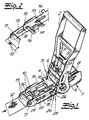
- a tensioning device for tensioning Belts or the like are shown in their basic Structure of a stenter 1, one on the stenter 1 pivotally mounted clamping lever 2 for actuating one in the Tensioning frame rotatably mounted belt winding shaft 3 with a Belt insertion slot 4 and with at least one on the Belt winding shaft 3 rotatably arranged ratchet wheel 5 with has locking teeth 6 oriented in the direction of rotation.
- Locking teeth 6 are resiliently mounted in the tensioning lever Drive pawl 7 as a drive mechanism and one in the Clamping frame 1 spring-loaded pawl 8 as a locking mechanism engaged.
- the tenter frame 1 has two opposite frame legs 10 on. Furthermore, a belt connection bolt 11 for a fixed belt 12 is provided. In the embodiment according to 1 to 4 of the belt connecting bolt 11 between two Guide cheeks 13 stored. The two guide cheeks 13 are on the outside of the two frame legs 10 in leg or. Cheek longitudinally guided. The frame legs 10 have aligned elongated holes 14. The elongated holes 14 are attached by one to the guide cheeks 13 Guide bar 15 penetrated.
- the locked in the starting position Guide cheeks 13 and the frame legs 10 of the Tensioning frame 1 is released by a predetermined after releasing the lock Measure and if necessary up to the stop of the guide rail 15 against that facing away from the belt winding shaft 3 Slotted ends in the way of relaxing the (partially) wound up Belt pulled apart.
- the frame legs 10 are at their ends facing away from the belt winding shaft 13 connected to each other by means of a crossbar 16. against the Crossbar 16 on the one hand and against the guide bar 15 on the other at least one attenuator 17 is supported.
- the Guide cheeks 13 have aligned slots 18.
- the Cross bar 16 engages on the outside over the frame legs 10 projecting web ends 19 into the elongated holes 18.
- the guide rail 15 has in the area of the elongated holes 14 of the frame legs 10 and the crossbar 16 or its web ends 19th point in the region of the elongated holes 18 of the guide cheeks 13 Width of the elongated holes 14, 18 corresponding constrictions that are not shown.
- Fig. 5 is the Belt connecting bolt 11 between two inner guide cheeks 13 stored.
- the two guide cheeks 13 are between the two frame legs 10 in the leg or cheek longitudinal direction flexibly guided. Furthermore, the guide cheeks 13 aligned slots 20 on.
- the elongated holes 20 are from a guide bar 21 attached to the frame legs 10 penetrated.
- the frame legs 10 of the tenter frame 1 and the locked guide cheeks 13 in the starting position after releasing the lock by a predetermined amount and if necessary until the guide bar 21 stops against the the belt winding shaft 3 facing elongated hole ends as required the belt tension pulled apart.
- the guide cheeks 13 are at their ends facing the belt winding shaft 3 below Formation of a U-shaped guide frame by means of a Base web 22 connected together.
- the attenuator 17 as Spring or rubber buffer or rubber / metal element his.
- the attenuator is preferred around a hydraulic cylinder piston arrangement 17 or around a Shock absorber.
- the guide cheeks 13 or the guide frame, e.g. from the belt connecting bolt 11, guide rail 15 and the guide cheeks 13 formed guide frames are by means of a locking device 23 held in the starting position.
- the locking device 23 has one or both sides pivotable on the outside of the frame legs 10 stored locking lever 24 on.
- the locking lever 24 reach over or under with a locking hook 25 13 projecting rod ends on the outside over the guide cheeks 26 of the guide rail 15 when in the starting position Guide frame.
- the locking lever 24 have a control cam 27, which with a control cam 28 on Lever arms of the tension lever 2 cooperate so that the release the locking device 23 by actuating the Clamping lever 2 can be done.
- this locking device 23 one on which the frame legs 10 connecting Crossbar 16 pivotally mounted ratchet 29 for the guide frame 11, 13, 15.
- the ratchet 29 locked the guide bar in the swiveled down locking position 15 of the lead frame.
- the locking mechanism 29 is an unlocking slide 30 assigned.
- the unlocking slide 30 is displaceable in the frame legs 10 of the clamping frame 1 stored.
- the lever arms of the tensioning lever 2 have on the winding shaft side Control cam 31, which when the lever is actuated and especially in the early stages of lever actuation the unlocking slide 30 against the locking mechanism 29 drive up and the locking mechanism 29 with the release of the guide rail 15 Swing up to unlock position.
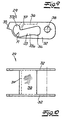
- the locking mechanism 29 has between the frame legs 10 stored guide legs 32 with aligned L-shaped Elongated holes 33 as a glide path for the guide bar 15 with the longer perforated legs 33a in the longitudinal direction of the Guide legs 32 and the shorter perforated legs 33b are angled upwards and in the locking position located ratchet 29 pick up the guide rail 15.
- the L-shaped elongated holes 33 point in the transition area from the longer perforated legs 33a to the shorter perforated legs 33b on the outer track side a predetermined sliding radius R.
- the longer perforated legs 33a have a diameter at the end the widening of the guide bar 15 exceeds 34
- Guide legs 32 of the locking mechanism 29 have the L-shaped ones Elongated holes 33 in the direction of the belt winding shaft 3 projecting extension 35 and lie with these extensions 35 on the unlocking slide 30th on.
- the guide legs 32 are below on their top Forming an inverted U-shaped locking body by means of a U base 36 connected to each other.
- the U base 36 faces a downward bend 37, which is an abutment for the guide bar 15 when in the locked position located ratchet 29 forms.
- the guide legs 32 point at their ends facing the crossbar 16 in alignment Bores 38 and are with these holes on the in Cross section circular cross bar 16 pivotally mounted, e.g.
- the locking mechanism 29 is under spring load in the locking position pressed.
- the locking mechanism 29 is below Interposition of at least one closing spring 39, e.g. Coil spring pivotally mounted on the crosspiece 16.
- the ratchet 29 is in manufacturing technology advantageously as a one-piece metal part educated.
- the unlocking slide 30 is in one against the extensions 35 of the guide legs 32 of the locking mechanism 29 directional inclined bearings stored and at least a compression spring 40, which is only indicated, which the unlocking slide 30 against the extensions 35 presses.
Landscapes
- Engineering & Computer Science (AREA)
- Transportation (AREA)
- Mechanical Engineering (AREA)
- Devices For Conveying Motion By Means Of Endless Flexible Members (AREA)
- Treatment Of Fiber Materials (AREA)
- Clamps And Clips (AREA)
Description
der Spannrahmen zwei sich gegenüberliegende Rahmenschenkel aufweist und ein zwischen zwei Führungswangen gelagerter Gurtanschlussbolzen für einen Festgurt vorgesehen ist,
wobei ferner
die Rahmenschenkel mittels eines Quersteges miteinander verbunden sind, wobei weiter
die beiden Führungswangen auf der Außenseite der beiden Rahmenschenkel oder dazwischen in Schenkel- bzw. Wangenlängsrichtung beweglich geführt sind, wobei darüber hinaus
die Führungswangen oder ein beispielsweise aus dem Gurtanschlussbolzen, einem Führungsholm und den Führungswangen gebildeter Führungsrahmen mittels einer Arretierungsvorrichtung in Ausgangsstellung gehalten werden bzw. wird, und wobei
die Rahmenschenkel fluchtende Langlöcher aufweisen, welche von einem an den Führungswangen befestigten Führungsholm durchdrungen sind, und
die in Ausgangsstellung arretierten Führungswangen und die Rahmenschenkel des Spannrahmens nach Lösen der Arretierung um ein vorgegebenes Maß und ggf. bis zum Anschlag des Führungsholms gegen die der Gurtwickelwelle abgewandten Langlochenden nach Maßgabe der Gurtspannung auseinandergezogen werden oder
die Führungswangen fluchtende Langlöcher aufweisen, welche von einem an den Rahmenschenkel befestigten Führungsholm durchdrungen sind und
die Rahmenschenkel des Spannrahmens und die in Ausgangsstellung arretierten Führungswangen nach Lösen der Arretierung um ein vorgegebenes Maß mit ggf. bis zum Anschlag des Führungsholms gegen die der Gurtwickelwelle zugewandten Langlochenden nach Maßgabe der Gurtspannung auseinandergezogen werden.
- Fig. 1
- eine bekannte Spannvorrichtung in perspektivischer Darstellung und Ausgangsstellung bei gespanntem, aber nicht gezeigtem Gurt,
- Fig. 2
- einen Ausschnitt aus dem Gegenstand nach Fig. 1 nach erfolgter Entspannung des aufgewickelten Gurtes,
- Fig. 3
- den Gegenstand nach Fig. 1 ohne Dämpfungsglied,
- Fig. 4
- eine abgewandelte Ausführungsform des Gegenstandes nach Fig. 1 mit einem anderen Dämpfungsglied,
- Fig. 5
- eine weitere abgewandelte Ausführungsform des Gegenstandes nach Fig. 1 mit zwischen den Rahmenschenkeln des Spannrahmens geführten Führungswangen,
- Fig. 6
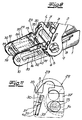
- eine erfindungsgemäß abgewandelte Ausführungsform des Gegenstandes nach Fig. 1 mit einer veränderten Arretierungsvorrichtung in schematischer Seitenansicht,
- Fig. 7
- den Gegenstand nach Fig. 6 bei in Entriegelungsstellung befindlichem Gesperre,
- Fig. 8
- den Gegenstand nach Fig. 7 in perspektivischer Darstellung,
- Fig. 9
- lediglich das Gesperre in schematischer Seitenansicht,
- Fig. 10
- den Gegenstand nach Fig. 9 in Draufsicht, und
- Fig. 11
- einen Ausschnitt aus dem Gegenstand nach Fig. 7 im Bereich des Entriegelungsschiebers.
Claims (20)
- Spannvorrichtung zum Spannen von Gurten oder dergleichen, mit einem Spannrahmen (1) und einem an dem Spannrahmen (1) schwenkbar gelagerten Spannhebel (2) zum Betätigen einer in dem Spannrahmen (1) drehbar gelagerten Gurtwickelwelle (3) sowie eines Antriebs- und Sperrmechanismus (5, 6, 7, 8) für die Gurtwickelwelle (3), wobei darüber hinaus die folgenden Merkmale verwirklicht sind:odera) der Spannrahmen (1) weist zwei sich gegenüberliegende Rahmenschenkel (10) auf;b) es ist ein zwischen zwei Führungswangen (13) gelagerter Gurtanschlussbolzen (11) für einen Festgurt (12) vorgesehen;c) die Rahmenschenkel (10) sind mittels eines Quersteges (16) miteinander verbunden;d) die beiden Führungswangen (13) sind auf der Außenseite der beiden Rahmenschenkel (10) oder dazwischen in Schenkel- bzw. Wangenlängsrichtung beweglich geführt;e) die Führungswangen (13) oder ein beispielsweise aus dem Gurtanschlussbolzen (11), einem Führungsholm (15) und den Führungswangen (13) gebildeter Führungsrahmen (11, 13, 15) werden bzw. wird mittels einer Arretierungsvorrichtung (23) in Ausgangsstellung gehalten;f1) die Rahmenschenkel (10) weisen fluchtende Langlöcher (14) auf, welche von einem an den Führungswangen (13) befestigten Führungsholm (15) durchdrungen sind, undg1) die in Ausgangsstellung arretierten Führungswangen (13) und die Rahmenschenkel (10) des Spannrahmens (1) werden nach Lösen der Arretierung um ein vorgegebenes Maß und ggf. bis zum Anschlag des Führungsholmes (15) gegen die der Gurtwickelwelle (3) abgewandten Langlochenden nach Maßgabe der Gurtspannung auseinandergezogen,dadurch gekennzeichnet, dassf2) die Führungswangen (13) weisen fluchtende Langlöcher (20) auf, die von einem an den Rahmenschenkeln (10) befestigten Führungsholm (21) durchdrungen sind, undg2) die Rahmenschenkel (10) des Spannrahmens (1) sowie die in Ausgangsstellung arretierten Führungswangen (13) werden nach Lösen der Arretierung um ein vorgegebenes Maß mit ggf. bis zum Anschlag des Führungsholms (21) gegen die der Gurtwickelwelle (3) zugewandten Langlochenden nach Maßgabe der Gurtspannung auseinandergezogen,
die Arretierungsvorrichtung (23) ein auf dem die Rahmenschenkel (10) verbindenden Quersteg (16) hochschwenkbar gelagertes Gesperre (29) aufweist. - Spannvorrichtung nach Anspruch 1, dadurch gekennzeichnet, dass die Rahmenschenkel (10) an ihren der Gurtwickelwelle (3) abgewandten Enden mittels des Quersteges (16) miteinander verbunden sind, und dass gegen den Quersteg (16) einerseits und gegen den Führungsholm (15) andererseits zumindest ein Dämpfungsglied (17) abgestützt ist.
- Spannvorrichtung nach Anspruch 1 oder 2, dadurch gekennzeichnet, dass die Führungswangen (13) fluchtende Langlöcher (18) aufweisen, und dass der Quersteg (16) mit außenseitig über die Rahmenschenkel (10) vorkragenden Stegenden (19) in die Langlöcher (18) eingreift.
- Spannvorrichtung nach einem der Ansprüche 1 bis 3, dadurch gekennzeichnet, dass der Führungsholm (15) im Bereich der Langlöcher (14) der Rahmenschenkel (10) und der Quersteg (16) bzw. seine Stegenden (19) im Bereich der Langlöcher (18) der Führungswangen (13) der Breite der Langlöcher (14, 18) entsprechende Einschnürungen aufweisen.
- Spannvorrichtung nach einem der Ansprüche 1 bis 4, dadurch gekennzeichnet, dass die Führungswangen (13) an ihren der Gurtwickelwelle (3) zugewandten Enden unter Bildung eines U-förmigen Führungsrahmens mittels eines Basissteges (22) miteinander verbunden sind, und dass gegen den Basissteg (22) einerseits und gegen den Führungsholm (21) andererseits zumindest ein Dämpfungsglied (17) abgestützt ist.
- Spannvorrichtung nach einem der Ansprüche 1 bis 5, dadurch gekennzeichnet, dass zur schwenkfreien Führung des Führungsrahmens (13, 22) der Führungsholm (21) einen breiten Querschnitt mit abgerundeten Stirnflächen aufweist, wobei der Holmquerschnitt an die Langlochbreite und die Stirnflächen an die Langlochenden angepasst sind.
- Spannvorrichtung nach einem der Ansprüche 1 bis 6, dadurch gekennzeichnet, dass das Dämpfungsglied (17) als eine Feder oder ein Gummipuffer oder ein Gummi/Metallelement ausgebildet ist.
- Spannvorrichtung nach einem der Ansprüche 1 bis 6, dadurch gekennzeichnet, dass das Dämpfungsglied (17) als eine pneumatische oder hydraulische Zylinderkolbenanordnung ausgebildet ist.
- Spannvorrichtung nach einem der Ansprüche 1 bis 6, dadurch gekennzeichnet, dass das Dämpfungsglied (17) als ein Stoßdämpfer ausgebildet ist.
- Spannvorrichtung nach einem der Ansprüche 1 bis 9, dadurch gekennzeichnet, dass das Gesperre (29) in niedergeschwenkter Verriegelungsstellung den Führungsholm (15) des Führungsrahmens (11, 13, 15) arretiert, und dass dem Gesperre (29) ein Entriegelungsschieber (30) zugeordnet und der Entriegelungsschieber (30) in den Rahmenschenkeln (10) des Spannrahmens (1) verschiebbar gelagert ist.
- Spannvorrichtung nach einem der Ansprüche 1 bis 10, dadurch gekennzeichnet, dass die Hebelarme des Spannhebels (2) Steuernocken (31) aufweisen, welche bei Spannhebelbetätigung den Entriegelungsschieber (30) gegen das Gesperre (29) hochfahren und das Gesperre (29) unter Freigabe des Führungsholms (15) in Entriegelungsstellung hochschwenken.
- Spannvorrichtung nach einem der Ansprüche 1 bis 11, dadurch gekennzeichnet, dass das Gesperre (29) zwischen den Rahmenschenkeln (10) gelagerte Führungsschenkel (32) mit fluchtenden L-förmigen Langlöchern (33) als Gleitweg für den Führungsholm (15) aufweist, wobei die längeren Lochschenkel (33a) in Längsrichtung der Führungsschenkel (32) verlaufen und die kürzeren Lochschenkel (33b) abgewinkelt sind und bei in Verriegelungsstellung befindlichem Gesperre (29) den Führungsholm (15) aufnehmen.
- Spannvorrichtung nach einem der Ansprüche 1 bis 12, dadurch gekennzeichnet, dass die L-förmigen Langlöcher (33) im Übergangsbereich von den längeren Lochschenkeln (33a) zu den kürzeren Lochschenkeln (33b) einen vorgegebenen Gleitradius aufweisen und die längeren Lochschenkel (33a) endseitig eine den Durchmesser des Führungsholms (15) übersteigende Aufweitung (34) besitzen.
- Spannvorrichtung nach einem der Ansprüche 1 bis 13, dadurch gekennzeichnet, dass die Führungsschenkel (32) des Gesperres (29) über die L-förmigen Langlöcher (33) hinaus eine in Richtung auf die Gurtwickelwelle (3) vorkragende Verlängerung (35) aufweisen und mit diesen Verlängerungen (35) auf dem Entriegelungsschieber (30) aufliegen.
- Spannvorrichtung nach einem der Ansprüche 1 bis 14, dadurch gekennzeichnet, dass die Führungsschenkel (32) auf ihrer Oberseite unter Bildung eines umgekehrt U-förmigen Sperrkörpers mittels einer U-Basis (36) miteinander verbunden sind und die U-Basis (36) eine Abwinklung (37) aufweist, die ein Widerlager für den Führungsholm (15) bei in Verriegelungsstellung befindlichem Gesperre (29) bildet.
- Spannvorrichtung nach einem der Ansprüche 1 bis 15, dadurch gekennzeichnet, dass die Führungsschenkel (32) an ihren dem Quersteg (16) zugewandten Enden fluchtende Bohrungen (38) aufweisen und mit diesen Bohrungen (38) auf dem im Querschnitt kreisförmigen Quersteg (16) schwenkbar gelagert sind, z.B. unter Zwischenschaltung einer Lagerhülse.
- Spannvorrichtung nach einem der Ansprüche 1 bis 16, dadurch gekennzeichnet, dass das Gesperre (29) unter Federbelastung in Verriegelungsstellung gedrückt ist.
- Spannvorrichtung nach einem der Ansprüche 1 bis 17, dadurch gekennzeichnet, dass das Gesperre (29) unter Zwischenschaltung von zumindest einer Schließfeder (39), z.B. Schraubenfeder auf dem Quersteg, schwenkbar gelagert ist.
- Spannvorrichtung nach einem der Ansprüche 1 bis 18, dadurch gekennzeichnet, dass das Gesperre (29) als einteiliges Metallteil ausgebildet ist.
- Spannvorrichtung nach einem der Ansprüche 1 bis 19, dadurch gekennzeichnet, dass der Entriegelungsschieber (30) in einer gegen die Verlängerungen (35) der Führungsschenkel (32) gerichteten Schrägführung gelagert und von einer oder mehreren Druckfedern (40) beaufschlagt bzw. gegen die Verlängerungen (35) gedrückt ist.
Applications Claiming Priority (2)
| Application Number | Priority Date | Filing Date | Title |
|---|---|---|---|
| DE19652109 | 1996-12-14 | ||
| DE19652109A DE19652109C2 (de) | 1996-09-04 | 1996-12-14 | Spannvorrichtung zum Spannen von Gurten oder dergleichen |
Publications (3)
| Publication Number | Publication Date |
|---|---|
| EP0848188A2 EP0848188A2 (de) | 1998-06-17 |
| EP0848188A3 EP0848188A3 (de) | 1999-06-23 |
| EP0848188B1 true EP0848188B1 (de) | 2002-12-04 |
Family
ID=7814749
Family Applications (1)
| Application Number | Title | Priority Date | Filing Date |
|---|---|---|---|
| EP97121945A Expired - Lifetime EP0848188B1 (de) | 1996-12-14 | 1997-12-13 | Spannvorrichtung zum Spannen von Gurten oder dergleichen |
Country Status (2)
| Country | Link |
|---|---|
| EP (1) | EP0848188B1 (de) |
| AT (1) | ATE229136T1 (de) |
Cited By (3)
| Publication number | Priority date | Publication date | Assignee | Title |
|---|---|---|---|---|
| DE202009017651U1 (de) | 2009-12-31 | 2010-04-08 | Future Product Entwicklungs- Und Vertriebsgesellschaft Mbh | Spannvorrichtung zum Spannen von Gurten |
| USD661562S1 (en) | 2010-06-18 | 2012-06-12 | Master Lock Company Llc | Ratchet |
| USD681411S1 (en) | 2011-08-30 | 2013-05-07 | Master Lock Company Llc | Ratchet lock |
Families Citing this family (1)
| Publication number | Priority date | Publication date | Assignee | Title |
|---|---|---|---|---|
| US7028833B2 (en) | 2004-04-09 | 2006-04-18 | Heimbach Gmbh & Co. | Method for connecting the belt ends of transport belts, as well as transport belt and closure aid for carrying out said method |
Family Cites Families (1)
| Publication number | Priority date | Publication date | Assignee | Title |
|---|---|---|---|---|
| DE29615284U1 (de) * | 1996-09-04 | 1996-10-31 | Westdeutscher Drahtseil-Verkauf Dolezych GmbH & Co, 44147 Dortmund | Spannvorrichtung zum Spannen von Gurten o.dgl. |
-
1997
- 1997-12-13 EP EP97121945A patent/EP0848188B1/de not_active Expired - Lifetime
- 1997-12-13 AT AT97121945T patent/ATE229136T1/de active
Cited By (5)
| Publication number | Priority date | Publication date | Assignee | Title |
|---|---|---|---|---|
| DE202009017651U1 (de) | 2009-12-31 | 2010-04-08 | Future Product Entwicklungs- Und Vertriebsgesellschaft Mbh | Spannvorrichtung zum Spannen von Gurten |
| USD661562S1 (en) | 2010-06-18 | 2012-06-12 | Master Lock Company Llc | Ratchet |
| USD675498S1 (en) | 2010-06-18 | 2013-02-05 | Master Lock Company Llc | Ratchet |
| USD681411S1 (en) | 2011-08-30 | 2013-05-07 | Master Lock Company Llc | Ratchet lock |
| USD729026S1 (en) | 2011-08-30 | 2015-05-12 | Master Lock Company Llc | Ratchet lock |
Also Published As
| Publication number | Publication date |
|---|---|
| ATE229136T1 (de) | 2002-12-15 |
| EP0848188A2 (de) | 1998-06-17 |
| EP0848188A3 (de) | 1999-06-23 |
Similar Documents
| Publication | Publication Date | Title |
|---|---|---|
| DE19851392B4 (de) | Vorrichtung zum zeitweiligen Verbinden eines bewegbaren Gegenstandes mit einer Halteschiene | |
| DE2717157C2 (de) | Gurt- bzw. Seil-Ratsche | |
| DE19851254C2 (de) | Gurtspanner | |
| DE102005013901B4 (de) | Baumständer, insbesondere Christbaumständer mit verbesserter Lösefunktion | |
| EP0281836B1 (de) | Gurtanschlussvorrichtung | |
| EP1526788B1 (de) | Seilwinde, insbesondere für den antrieb eines schirmes | |
| EP0504557B1 (de) | Spann- und Zurrvorrichtung für Zurrstränge | |
| EP1839915B1 (de) | Spannvorrichtung für eine Gleitschutzkette | |
| EP2154009A1 (de) | Spannschloss | |
| DE19652109C2 (de) | Spannvorrichtung zum Spannen von Gurten oder dergleichen | |
| DE102014108902B4 (de) | Spannschloss für eine Gleitschutzkette | |
| DE2759085A1 (de) | Fangvorrichtung fuer eine mindestens ein seil aufweisende hubvorrichtung | |
| EP0848188A2 (de) | Spannvorrichtung zum Spannen von Gurten oder dergleichen | |
| DE10015048C5 (de) | Gurtaufroller mit einer als Blechbiegebremse ausgebildeten Kraftbegrenzungseinrichtung | |
| EP2086773B1 (de) | Spannschloss für eine gleitschutzkette | |
| AT504476B1 (de) | Spannschloss für eine gleitschutzkette | |
| DE19839245C1 (de) | Spannvorrichtung für Gurte und dergleichen | |
| DE29823091U1 (de) | Spannvorrichtung für ein flexibles Zugelement einer Markise | |
| EP2070735B1 (de) | Spannvorrichtung für eine Reifenkette | |
| EP1586730B1 (de) | Sicherungsblockademittel für ein Deckenlauftor | |
| DE2728790A1 (de) | Spanneinrichtung fuer ketten | |
| EP1071859B1 (de) | Schliessvorrichtung für flügelfenster und flügeltüren | |
| EP2730733A2 (de) | Tor | |
| DE2027921C3 (de) | Tiefbaustrebe | |
| DE1431205C (de) |
Legal Events
| Date | Code | Title | Description |
|---|---|---|---|
| PUAI | Public reference made under article 153(3) epc to a published international application that has entered the european phase |
Free format text: ORIGINAL CODE: 0009012 |
|
| AK | Designated contracting states |
Kind code of ref document: A2 Designated state(s): AT CH DE LI SE |
|
| AX | Request for extension of the european patent |
Free format text: AL;LT;LV;MK;RO;SI |
|
| PUAL | Search report despatched |
Free format text: ORIGINAL CODE: 0009013 |
|
| AK | Designated contracting states |
Kind code of ref document: A3 Designated state(s): AT BE CH DE DK ES FI FR GB GR IE IT LI LU MC NL PT SE |
|
| AX | Request for extension of the european patent |
Free format text: AL;LT;LV;MK;RO;SI |
|
| 17P | Request for examination filed |
Effective date: 19990714 |
|
| AKX | Designation fees paid |
Free format text: AT CH DE LI SE |
|
| 17Q | First examination report despatched |
Effective date: 20010702 |
|
| GRAG | Despatch of communication of intention to grant |
Free format text: ORIGINAL CODE: EPIDOS AGRA |
|
| GRAG | Despatch of communication of intention to grant |
Free format text: ORIGINAL CODE: EPIDOS AGRA |
|
| GRAH | Despatch of communication of intention to grant a patent |
Free format text: ORIGINAL CODE: EPIDOS IGRA |
|
| GRAH | Despatch of communication of intention to grant a patent |
Free format text: ORIGINAL CODE: EPIDOS IGRA |
|
| GRAA | (expected) grant |
Free format text: ORIGINAL CODE: 0009210 |
|
| AK | Designated contracting states |
Kind code of ref document: B1 Designated state(s): AT CH DE LI SE |
|
| REF | Corresponds to: |
Ref document number: 229136 Country of ref document: AT Date of ref document: 20021215 Kind code of ref document: T |
|
| REG | Reference to a national code |
Ref country code: CH Ref legal event code: NV Representative=s name: KELLER & PARTNER PATENTANWAELTE AG Ref country code: CH Ref legal event code: EP |
|
| REF | Corresponds to: |
Ref document number: 59708884 Country of ref document: DE Date of ref document: 20030116 |
|
| REG | Reference to a national code |
Ref country code: SE Ref legal event code: TRGR |
|
| PLBE | No opposition filed within time limit |
Free format text: ORIGINAL CODE: 0009261 |
|
| STAA | Information on the status of an ep patent application or granted ep patent |
Free format text: STATUS: NO OPPOSITION FILED WITHIN TIME LIMIT |
|
| 26N | No opposition filed |
Effective date: 20030905 |
|
| PGFP | Annual fee paid to national office [announced via postgrant information from national office to epo] |
Ref country code: CH Payment date: 20121221 Year of fee payment: 16 |
|
| PGFP | Annual fee paid to national office [announced via postgrant information from national office to epo] |
Ref country code: SE Payment date: 20121220 Year of fee payment: 16 |
|
| PGFP | Annual fee paid to national office [announced via postgrant information from national office to epo] |
Ref country code: AT Payment date: 20121212 Year of fee payment: 16 |
|
| REG | Reference to a national code |
Ref country code: SE Ref legal event code: EUG |
|
| REG | Reference to a national code |
Ref country code: CH Ref legal event code: PL |
|
| REG | Reference to a national code |
Ref country code: AT Ref legal event code: MM01 Ref document number: 229136 Country of ref document: AT Kind code of ref document: T Effective date: 20131213 |
|
| PG25 | Lapsed in a contracting state [announced via postgrant information from national office to epo] |
Ref country code: SE Free format text: LAPSE BECAUSE OF NON-PAYMENT OF DUE FEES Effective date: 20131214 |
|
| PG25 | Lapsed in a contracting state [announced via postgrant information from national office to epo] |
Ref country code: CH Free format text: LAPSE BECAUSE OF NON-PAYMENT OF DUE FEES Effective date: 20131231 Ref country code: LI Free format text: LAPSE BECAUSE OF NON-PAYMENT OF DUE FEES Effective date: 20131231 |
|
| PG25 | Lapsed in a contracting state [announced via postgrant information from national office to epo] |
Ref country code: AT Free format text: LAPSE BECAUSE OF NON-PAYMENT OF DUE FEES Effective date: 20131213 |
|
| PGFP | Annual fee paid to national office [announced via postgrant information from national office to epo] |
Ref country code: DE Payment date: 20161229 Year of fee payment: 20 |
|
| REG | Reference to a national code |
Ref country code: DE Ref legal event code: R071 Ref document number: 59708884 Country of ref document: DE |