EP0847904B1 - Aufblasbare Schutzeinrichtung für Fahrzeuginsassen - Google Patents
Aufblasbare Schutzeinrichtung für Fahrzeuginsassen Download PDFInfo
- Publication number
- EP0847904B1 EP0847904B1 EP97307256A EP97307256A EP0847904B1 EP 0847904 B1 EP0847904 B1 EP 0847904B1 EP 97307256 A EP97307256 A EP 97307256A EP 97307256 A EP97307256 A EP 97307256A EP 0847904 B1 EP0847904 B1 EP 0847904B1
- Authority
- EP
- European Patent Office
- Prior art keywords
- curtain
- vehicle
- inflatable restraint
- inflatable
- deployment
- Prior art date
- Legal status (The legal status is an assumption and is not a legal conclusion. Google has not performed a legal analysis and makes no representation as to the accuracy of the status listed.)
- Expired - Lifetime
Links
- 239000012858 resilient material Substances 0.000 claims description 6
- 238000000034 method Methods 0.000 claims description 5
- 238000005728 strengthening Methods 0.000 claims description 3
- 230000000977 initiatory effect Effects 0.000 claims description 2
- 241000826860 Trapezium Species 0.000 description 4
- 238000004891 communication Methods 0.000 description 3
- 239000012530 fluid Substances 0.000 description 3
- 208000027418 Wounds and injury Diseases 0.000 description 2
- 230000006378 damage Effects 0.000 description 2
- 239000004744 fabric Substances 0.000 description 2
- 239000011521 glass Substances 0.000 description 2
- 208000014674 injury Diseases 0.000 description 2
- 238000005452 bending Methods 0.000 description 1
- 230000008602 contraction Effects 0.000 description 1
- 210000005069 ears Anatomy 0.000 description 1
- 239000013536 elastomeric material Substances 0.000 description 1
- 239000002360 explosive Substances 0.000 description 1
- 238000004519 manufacturing process Methods 0.000 description 1
- 239000000463 material Substances 0.000 description 1
- 239000002184 metal Substances 0.000 description 1
- 230000000452 restraining effect Effects 0.000 description 1
- 239000000126 substance Substances 0.000 description 1
- 238000013022 venting Methods 0.000 description 1
Images


Classifications
-
- B—PERFORMING OPERATIONS; TRANSPORTING
- B60—VEHICLES IN GENERAL
- B60R—VEHICLES, VEHICLE FITTINGS, OR VEHICLE PARTS, NOT OTHERWISE PROVIDED FOR
- B60R21/00—Arrangements or fittings on vehicles for protecting or preventing injuries to occupants or pedestrians in case of accidents or other traffic risks
- B60R21/02—Occupant safety arrangements or fittings, e.g. crash pads
- B60R21/16—Inflatable occupant restraints or confinements designed to inflate upon impact or impending impact, e.g. air bags
- B60R21/23—Inflatable members
- B60R21/231—Inflatable members characterised by their shape, construction or spatial configuration
- B60R21/2334—Expansion control features
- B60R21/2338—Tethers
-
- B—PERFORMING OPERATIONS; TRANSPORTING
- B60—VEHICLES IN GENERAL
- B60R—VEHICLES, VEHICLE FITTINGS, OR VEHICLE PARTS, NOT OTHERWISE PROVIDED FOR
- B60R21/00—Arrangements or fittings on vehicles for protecting or preventing injuries to occupants or pedestrians in case of accidents or other traffic risks
- B60R21/02—Occupant safety arrangements or fittings, e.g. crash pads
- B60R21/16—Inflatable occupant restraints or confinements designed to inflate upon impact or impending impact, e.g. air bags
- B60R21/23—Inflatable members
- B60R21/231—Inflatable members characterised by their shape, construction or spatial configuration
- B60R21/232—Curtain-type airbags deploying mainly in a vertical direction from their top edge
-
- B—PERFORMING OPERATIONS; TRANSPORTING
- B60—VEHICLES IN GENERAL
- B60R—VEHICLES, VEHICLE FITTINGS, OR VEHICLE PARTS, NOT OTHERWISE PROVIDED FOR
- B60R21/00—Arrangements or fittings on vehicles for protecting or preventing injuries to occupants or pedestrians in case of accidents or other traffic risks
- B60R21/02—Occupant safety arrangements or fittings, e.g. crash pads
- B60R21/16—Inflatable occupant restraints or confinements designed to inflate upon impact or impending impact, e.g. air bags
- B60R21/23—Inflatable members
- B60R21/231—Inflatable members characterised by their shape, construction or spatial configuration
- B60R21/2334—Expansion control features
- B60R21/2338—Tethers
- B60R2021/23386—External tether means
-
- B—PERFORMING OPERATIONS; TRANSPORTING
- B60—VEHICLES IN GENERAL
- B60R—VEHICLES, VEHICLE FITTINGS, OR VEHICLE PARTS, NOT OTHERWISE PROVIDED FOR
- B60R21/00—Arrangements or fittings on vehicles for protecting or preventing injuries to occupants or pedestrians in case of accidents or other traffic risks
- B60R21/02—Occupant safety arrangements or fittings, e.g. crash pads
- B60R21/16—Inflatable occupant restraints or confinements designed to inflate upon impact or impending impact, e.g. air bags
- B60R21/23—Inflatable members
- B60R21/231—Inflatable members characterised by their shape, construction or spatial configuration
- B60R21/23184—Tubular air bags connected to the vehicle at their two extremities
-
- B—PERFORMING OPERATIONS; TRANSPORTING
- B60—VEHICLES IN GENERAL
- B60R—VEHICLES, VEHICLE FITTINGS, OR VEHICLE PARTS, NOT OTHERWISE PROVIDED FOR
- B60R21/00—Arrangements or fittings on vehicles for protecting or preventing injuries to occupants or pedestrians in case of accidents or other traffic risks
- B60R21/02—Occupant safety arrangements or fittings, e.g. crash pads
- B60R21/16—Inflatable occupant restraints or confinements designed to inflate upon impact or impending impact, e.g. air bags
- B60R21/23—Inflatable members
- B60R21/239—Inflatable members characterised by their venting means
Definitions
- the invention relates to an inflatable restraint for a vehicle occupant, a vehicle having such restraint and a method of deploying such restraint.
- Air bags are increasingly fitted as standard equipment on production vehicles in the US and in the European market.
- An air bag mounted on a steering column to protect the driver and an air bag mounted in the dashboard to protect the passenger is a typical arrangement for providing occupant protection in the event of a front end collision.
- a sensor is strategically placed on the vehicle and operation of the sensor is arranged to fire a pyrotechnic gas generator to inflate the air bag.
- US Patent No.5480181 discloses a braided tubular bag which is arranged to contract longitudinally as the diameter of the tube increases. In a deflated state the tube is arranged along the door pillar and the roof rail of the vehicle. In the event of an impact the tube is inflated by a gas generator. The tube contracts longitudinally and forms a taut semi-rigid structural member across the vehicle side window.
- the inflated tube is relatively rigid and may not, therefore, provide the most desirable form of cushioning for the driver or passenger whose head impacts the tube.
- DE4337656 discloses an occupant protection device for vehicles comprising a piece of fabric 19 arranged within the roof line of a vehicle which can be pulled into an occupant protection position by a cable 17.
- WO93/09977 relates to a safety device according to the preamble of claim 1, in which a restraining means 3 in the form of a net is deployed together with an airbag 25.
- EP0590518 relates to an air bag in the form of a ring with a non-inflated fabric part 16 filling the centre part of the ring.
- WO96/26087 relates to a safety device for a motor vehicle comprising an inflatable restraint for side impact protection. It does not include a deployment member for moving the restraint into an occupant protection position.
- an inflatable restraint for a vehicle occupant comprising an inflatable curtain and a deployment member for moving the curtain into an occupant protection position, the deployment member comprising a resilient member which is held in an extended state under tension when the curtain is in an un-deployed state and the resilient member is released from tension to deploy the curtain, characterised in that the resilient member is connected along the lower edge of the curtain and comprises a length of resilient material, said length of resilient material is mountable to the vehicle at two spaced mounting points and is held in its un-deployed state under tension by an operable latch suitable to be arranged between said mounting points.
- the latch may be actuated by a solenoid.
- the solenoid may be operable by a pressure sensor connected to the inflating means.
- the solenoid may be operable on receipt of a signal, said signal also initiating the inflating means.
- the curtain may include strengthening ribs.
- the curtain may include tubes which are inflated before the remainder of the curtain to provide structural strength to the curtain.
- the inflatable tubes may constitute the aforesaid ribs. Alternatively tubes and ribs may be provided.
- the curtain may include an air bag which, in use, is located at head height to protect the head of a vehicle occupant. Such a bag may receive inflation gas from within the curtain to inflate the bag.
- the curtain may include inflatable members which, on inflation, bring the air bags into an operative position.
- the curtain may include a member such as one or more tubes formed so as to direct the curtain away from an obstruction in the vehicle.
- the member preferably directs the curtain away from a seat belt.
- the member preferably acts against an existing member in the vehicle, for instance a door pillar.
- the curtain preferably vents to atmosphere, after inflation.
- the curtain preferably deploys downwardly.
- the curtain preferably has mounting means thereon to enable the curtain to be mounted on a body of the vehicle.
- the mounting means may be located in a sleeve in the curtain which may be positioned along an upper edge of the curtain.
- a vehicle having therein an inflatable restraint according to the first aspect of the invention or any of the consistory clauses relating thereto.
- the curtain is preferably located inside the vehicle to one side thereof.
- the curtain may be located along one whole side of the vehicle.
- one curtain may be located at the front of the vehicle and another curtain may be located at the rear.
- the front and rear curtains may overlap.
- the curtain may be located in a slot in a roof rail of the vehicle and/or in a slot in the door pillar of the vehicle.
- a plurality of deployment members may be provided.
- the deployment members may be linked by structural members.
- the structural members preferably provide structural rigidity to the curtain upon deployment and inflation thereof.
- a third aspect of the invention there is provided a method of deploying an inflatable restraint for a vehicle occupant according to the first aspect of the invention comprising the steps of claim 17.
- a restraint 10 which does not fall within the terms of the present claim, is located adjacent a vehicle side window 12.
- the restraint 10 comprises a generally triangular inflatable curtain 14 (see Fig.1b) with a braided tube deployment member 16 connected to the curtain 14 along a lower edge thereof.
- the curtain 14 is hollow with opposite triangular faces sealed around their edges to each other.
- the term "inflatable curtain” is intended to cover any sheet-like member, at least part of which may be inflated. Thus all of the arrangements shown in Fig. 18 are encompassed by the term "inflatable curtain".
- the deployment member 16 is mounted to the vehicle at spaced mounting points 18, 20.
- the mounting point 18 is located adjacent the forward upper comer of the window 12 and the mounting point 20 is located adjacent the rearward lower corner of the window 12.
- the curtain 14 is secured to the vehicle at mounting point 22 which is located adjacent the rearward upper corner of the window 12 such that the curtain is arranged around the perimeter of the window in the undeployed state.
- a source of gas under pressure such as a gas generator 24 is connected by pipes 26, 28 to the curtain 14 and the deployment member 16 respectively.
- the gas generator 24 is electrically connected to a crash sensor 30 which is arranged to sense impact of the vehicle with an obstruction in the region of the restraint.
- the braided tube deployment member 16 comprises a braided tube 32 enclosing a gas impermeable tube 34 connected to the pipe 28 of the gas generator 24.
- Fig 1a shows the restraint in an undeployed state.
- the deployment member 16 In its undeployed state the deployment member 16 is arranged in a recess (not shown) which runs along the top of the window 12 and down the rear side of the window 12.
- the curtain 14 is deflated and furled in the recess.
- the curtain 14 is folded in such a manner that, on deployment, it exits the recess quickly for inflation.
- the gas generator 24 includes an explosive substance which, on exploding, produces large volumes of gas very quickly. In the present case the generator produces approximately 20 litres of gas in about ten milliseconds.
- the gas generator 24 inflates the gas impermeable tube 34 via pipe 28. On inflation, the impermeable tube 34 increases in diameter which, in turn, increases the diameter of the braided tube 32. The increase in diameter of the braided tube 32 causes the tube 32 to contract longitudinally. That contraction causes the deployment member 16 to snap out of the recess to a position taught between the mounting points 18, 20 in the manner of a bow string. The deployment member 16 pulls the curtain 14 from the recess and the curtain 14 is inflated with gas from the generator 24 via pipe 26.
- the restraint 10 can be used in a situation where deployment time is limited, for instance in a side impact.
- the deployment member 16 ensures that the curtain is deployed quickly and the curtain 14 provides a useful restraint which reduces the risk of injury to vehicle occupants and protects against ingress of broken glass and foreign bodies.
- Figs. 2a and 2b show restraint 36 in accordance with the first aspect of the invention. Parts corresponding to parts in Figs 1a and 1b carry the same reference numerals.
- the restraint 36 comprises a curtain 14 and an elastic deployment member 38.
- the curtain 14 is substantially similar to that of Figs 1a and 1b except that it is trapezium shaped and is mounted at mounting points 22a, 22b which are spaced diagonally either side of the rear upper corner of the window 12.
- the elastic deployment member 38 comprises a length of resilient material, preferably an elastomeric material.
- the member 38 is mounted at mounting points 18, 20 in similar manner to that shown in Figs 1a and 1b.
- the elastic deployment member is connected along the lower edge of the curtain 14.
- the elastic deployment member 38 is held under tension in its undeployed state by a latch 40.
- the latch 40 comprises a solenoid 42 which is actuated by means of a pressure switch 44.
- the pressure switch 44 is connected by means of a pipe 46 to the gas generator 24.
- the solenoid 42 may be actuated by a signal from the crash sensor 30 which also initiates the gas generator 24.
- Fig 2a shows the restraint 36 in an undeployed state.
- the elastic deployment member 38 extends from the mounting point 18 along the top of the window 12 to the latch 40 and then down the rear side of the window 12 to the mounting point 20.
- the curtain 14 and deployment member 38 are located in a recess in similar manner to Fig 1a and 1b.
- the gas generator 24 is connected to a crash sensor 30.
- the sensor 30 actuates the gas generator 24.
- Gas is injected into the curtain 14 via the pipe 26 and gas also travels along the pipe 46 to the pressure switch 44.
- the pressure switch 44 actuates the solenoid 42 to release the elastic deployment member.
- the elastic deployment member 38 which, in the undeployed state, is held under tension, snaps taught, in the manner of a bow string. The elastic deployment member 38 pulls the curtain 14 from the recess and the curtain is inflated.
- Figs 3 to 6 show arrangements of inflatable restraints in accordance with the invention in a vehicle.
- Figs 3a and 3b show a restraint 48 which extends from a point adjacent the lower front corner of a driver window 12a of a vehicle 50 to a point adjacent the lower rear corner of the passenger window 12b of the vehicle 50.
- Fig 3b shows the restraint 48 of Fig 3a in a deployed state.
- Fig 4a shows inflatable restraints 52, 54 for driver and passenger windows 12a, 12b respectively.
- Fig 4b shows the restraints 52, 54 in a deployed state.
- Fig 5a shows an inflatable restraint 56 in the vehicle 50 which extends from the upper front corner of the driver window 12a to the lower rear corner of the passenger window 12b.
- Fig 5b shows the restraint 56 in a deployed state.
- Fig 6a shows a pair of restraints.
- the first restraint 56 is similar to that shown in Fig 5a and 5b.
- the second restraint 58 extends from the lower front corner of driver window 12a to the upper rear corner of the passenger window 12b.
- Fig 6b which shows the restraints 56, 58 in their deployed states, the restraints 56, 58 overlap to provide a restraint along the whole side of the vehicle 50.
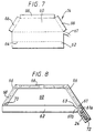
- Fig 7 shows a curtain part 14 of a restraint 48 similar to that shown in Fig 3.
- the curtain part 14 is shown folded out flat.
- the curtain part 14 comprises a substantially trapezium shaped central part 60 which is connected at a corner to a pipe 61.
- a rectangular flap 62 which can be folded back on itself along a fold line 64 to form a tube for receiving a deployment member 38.
- Mounting member receiving flaps 66 extend from the other edges of the trapezium shaped central portion 60.
- the flaps 66 are arranged to be folded back on themselves to form a tube to receive mounting members (see Fig 8).
- Fig 8 shows the curtain part 14 with the flaps 62, 66 shown in their folded positions.
- the flaps 66 receive mounting members 68.
- Each mounting member 68 comprises an elongate metal plate with regularly spaced holes 70 which receive fasteners for fastening the curtain 14 to the vehicle 50.
- the curtain 14 is shown attached by pipe 61 to a gas generator 24 which is mounted on a gas generator mounting 72.
- the pipe 61 has a flap 63 therein which divides the pipe 61 into passages 61a, 61b.
- the passage 61a leads to the interior of the central portion 60.
- the passage 61b leads to the tube formed by the flap 62 for connection to a braided tube deployment member 16, which does not belong to the invention.
- the gas generator mounting 72 is shown in more detail in Fig 9.
- the gas generator mounting 72 comprises a bracket 74 with spaced gas generator receiving loops 76 thereon.
- the bracket 74 has tabs 78 which are received in slots 80 of a gas generator mounting plate 82.
- the mounting plate 82 has holes 84 for receiving fasteners which fasten the generator mounting 72 to the vehicle 50.
- the gas generator 24 is received in the pipe 61.
- the bracket is then pushed over the generator 24 which is surrounded by the pipe 61.
- the loops 76 secure the generator 24 in place.
- the pipe 61 has apertures 65 therein and the tabs 78 pass through the pipe apertures 65.
- the bracket 74 is attached to the mounting plate 82 by inserting the tabs 78 through the respective slots 80 and bending the tabs over to secure the bracket 74 to the plate 82. Once assembled, the loops 76 and the plate 82 secure the pipe 61 around the generator 24 in a gas-tight manner. The plate 82 can then be secured to the vehicle by fasteners extending through the holes 84. The gas generator 24 is arranged in fluid communication with the restraint 48 via the pipe 61.
- the bracket 74 may be fastened to the plate 82 by other fasteners, such as screws (not shown). The fasteners may secure the bracket 74 to the plate 82 and the assembly to the vehicle 50.
- Fig 10 shows the central portion 60 of the curtain 14.
- the central portion 60 has an internal arrangement of tubes 86 which are inflated before the remainder of the central portion 60 to provide the curtain 14 with structural rigidity.
- the arrangement of tubes comprises a tube 88 which extends around the upper periphery of the portion 60 and four tubes 90, 92, 94,96 depending downwardly therefrom.
- the four tubes 90, 92, 94, 96 vent to atmosphere via restrictors which are represented schematically in Fig 10.
- the tube 88 opens to the interior of the curtain.
- vent holes are provided in the tube 88 and the tube 92 which vent to air bags 98 for the heads of vehicle occupants (see Figs 11a, 11b).
- the tubes are preferably arranged, on inflation, to bring the air bags 98 into positions suitable for protecting vehicle occupants, for instance, adjacent a door pillar of the vehicle.
- Embodiments of head air bags 98 are shown in Figs 11a and 11b.
- the air bag 98 comprises an air bag having two vent holes to allow venting from the curtain 14 to the bag 98.
- the head air bag 98 has three ears 100 protruding therefrom which have vent holes therein and which help to locate the bag, upon inflation.
- Fig 12 is a schematic sectional view of a vehicle 50 showing the location of the restraint 10 in its undeployed state.
- the vehicle 50 has a ceiling lining 102 and a door pillar 104, defining a recess 106 therebetween.
- the recess 106 receives the restraint 10 and the restraint is concealed by means of a finisher 108 which is attached to the ceiling liner 102 by means of fastenings 110.
- the finisher 108 comprises an elongate strip of resilient material 112 which extends across the recess 106 between the ceiling lining 102 and the door pillar 104.
- Figs 13a and 13b show schematically a restraint in accordance with a first aspect of the invention in which multiple deployment members are used. In that way, the restraint can be deployed even more quickly and the deployment members 38a, 38b, 38c provide additional structural rigidity to the curtain 14 when inflated.
- additional structural members 114 are provided between the multiple deployment members 38a, 38b, 38c to provide improved rigidity.
- the structural members 114 are ribs or loops of material which are secured at each end to respective deployment members 38a, 38b, 38c.
- Fig 16 shows part of a restraint in accordance with the third aspect of the invention.
- the restraint 130 comprises a curtain 132 having an internal tubular arrangement 134, 136, 138, 140 which is similar in many respects to that shown in Fig 10.
- the tubular arrangement comprises a tube 136 which extends around the upper periphery of the curtain and four downwardly depending tubes, three of which are shown.
- the middle two downwardly depending tubes 138,140 are substantially conical, having their large end towards a lower part of the curtain 132.
- the conical tubes 138, 140 When the curtain of Fig 16 is deployed the conical tubes 138, 140 are filled.
- the conical tubes 138, 140 act against a door pillar 142 of the vehicle 50.
- the tubes 138, 140 push the curtain 132 away from the door pillar 142 so as to hold the curtain clear of a seat belt 144 attached to the door pillar 142.
- Fig 17 shows the curtain of Fig 16 looking in the direction of arrow XVII in Fig 16. It can be seen from Fig 17 that the conical tube 140 and tube 138 (not shown) holds the curtain 132 clear from the seat belt 144.
- Figs 16 and 17 are advantageous since it avoids interference with the seat belt, which may knock the seat belt off the shoulder of the wearer in a crash.
- Fig 18 shows a number of configurations of inflatable curtain 14 with various internal arrangements of tubing.
- the hatched portions show the areas inflated in the event of a crash.
- the tubing may be in fluid communication with the remainder of the curtain whereby the gas generator inflates the tubular arrangement and then the gas in the tubes leaks out to the remainder of the curtain to inflate the remainder.
- the tubular arrangement could be sealed so that just the tubes are inflated.
- the restraints described above for are especially useful as side impact restraints as the invention provides a method of deploying a large restraint quickly within the time scale afforded by a side impact.
Landscapes
- Engineering & Computer Science (AREA)
- Mechanical Engineering (AREA)
- Air Bags (AREA)
Claims (17)
- Aufblasbare Rückhaltevorrichtung (10) für einen Fahrzeuginsassen, die einen aufblasbaren Vorhang (14) und ein Entfaltungselement (38) umfaßt, um den Vorhang (14) in eine Insassenschutzposition zu bewegen, wobei das Entfaltungselement ein elastisches Element (38) umfaßt, das in einem gestreckten Zustand unter Spannung gehalten wird, wenn sich der Vorhang in einem nicht-entfalteten Zustand befindet, und das elastische Element (38) von der Spannung freigegeben wird, um den Vorhang (14) zu entfalten, dadurch gekennzeichnet, daß das elastische Element (38) längs der Unterkante des Vorhangs (14) verbunden ist und eine Länge eines elastischen Materials (38) umfaßt, wobei die Länge elastischen Materials (38) an zwei mit Zwischenraum angeordneten Einbaupunkten (18, 20) an dem Fahrzeug eingebaut werden kann und im nicht-entfalteten Zustand durch eine betätigbare Klinke (40) unter Spannung gehalten wird, die dafür geeignet ist, zwischen den Einbaupunkten (18, 20 (i. Orig. hier: 29. Anm. d. Ü.)) angeordnet zu werden.
- Aufblasbare Rückhaltevorrichtung nach Anspruch 1, bei der das elastische Entfaltungselement (38) durch eine elektromagnetisch betätigte Klinke (40) unter Spannung gehalten wird.
- Aufblasbare Rückhaltevorrichtung nach Anspruch 2, bei der die Magnetspule (42) mit Hilfe eines Drucksensors (44) betätigt werden kann, der mit Aufblasmitteln (24) zum Aufblasen des Vorhangs (14) verbunden ist.
- Aufblasbare Rückhaltevorrichtung nach Anspruch 2, bei der die Magnetspule (42) bei Empfang eines Signals betätigt werden kann, wobei das Signal ebenfalls die Aufblasmittel (24) zum Aufblasen des Vorhangs (14) startet.
- Aufblasbare Rückhaltevorrichtung nach einem der vorhergehenden Ansprüche, bei der wenigstens ein weiteres Entfaltungselement (38b) bereitgestellt wird, wobei das weitere Entfaltungselement (38b) nicht längs der Unterkante des Vorhangs verbunden ist.
- Aufblasbare Rückhaltevorrichtung nach Anspruch 5, bei der das Entfaltungselement (38) und das weitere Entfaltungselement (38b) durch Strukturelemente (114) verbunden werden, um so dem Vorhang (14) nach der Entfaltung desselben strukturelle Steifigkeit zu geben.
- Aufblasbare Rückhaltevorrichtung nach einem der vorhergehenden Ansprüche, bei welcher der Vorhang (14) Verstärkungsrippen (114) einschließt.
- Aufblasbare Rückhaltevorrichtung nach einem der vorhergehenden Ansprüche, bei welcher der Vorhang (14) Schläuche (134, 136, 138, 140) einschließt, die angeordnet sind, um vor dem Rest des Vorhangs (14) aufgeblasen zu werden, um dem Vorhang (14) strukturelle Festigkeit zu geben und das richtige Entfalten zu unterstützen.
- Aufblasbare Rückhaltevorrichtung nach einem der vorhergehenden Ansprüche, bei welcher der Vorhang (14) einen Airbag (98) hat, der so angeordnet ist, daß sich der Airbag (98) in der Kopfhöhe eines Insassen befindet, wenn der Vorhang (14) entfaltet wird.
- Aufblasbare Rückhaltevorrichtung nach Anspruch 9, bei welche der Airbag (98) oder der Vorhang (14) ein aufblasbares Element (88) hat, um den Airbag in eine betriebsbereite Position zu bringen.
- Aufblasbare Rückhaltevorrichtung nach einem der vorhergehenden Ansprüche, bei welcher der Vorhang (14) ein aufblasbares Führungselement (138, 140) einschließt, um den Vorhang von einem Hindernis in einem Fahrzeug weg zu leiten
- Aufblasbare Rückhaltevorrichtung nach einem der vorhergehenden Ansprüche, bei welcher der Vorhang (14) sich nach unten in eine Insassenschutzposition entfaltet.
- Fahrzeug (50) mit einer aufblasbaren Rückhaltevorrichtung (10) nach einem der vorhergehenden Ansprüche in denselben.
- Fahrzeug (50) nach Anspruch 13, bei dem sich der Vorhang (14) längs einer ganzen Seite des Innern des Fahrzeugs (50) befindet.
- Fahrzeug (50) nach Anspruch 13, bei dem sich ein Vorhang (14) vorn auf einer Seite des Innern des Fahrzeugs (50) befindet und sich ein zweiter Vorhang (14) hinten auf der Seite des Innern des Fahrzeugs (50 (i. Orig. hier: 80. Anm. d. Ü.)) befindet.
- Fahrzeug nach Anspruch 13, 14 oder 15, bei dem sich der Vorhang (14) in einem Dachholm des Fahrzeugs (50) und/oder in einem Schlitz in einem oder mehreren Türpfosten des Fahrzeugs befindet.
- Verfahren zum Entfalten einer aufblasbaren Rückhaltevorrichtung (10) für einen Fahrzeuginsassen nach einem der vorhergehenden Ansprüche, wobei das Verfahren die folgenden Schritte umfaßt: Halten des elastischen Elements (38) in einem gestreckten Zustand unter Spannung, Freigeben des elastischen Elements (38), so daß es sich in Längsrichtung zusammenzieht, um so den Vorhang (14) in eine Insassenschutzposition zu bewegen.
Applications Claiming Priority (2)
| Application Number | Priority Date | Filing Date | Title |
|---|---|---|---|
| GBGB9619613.4A GB9619613D0 (en) | 1996-09-19 | 1996-09-19 | An inflatable restraint for a vehicle |
| GB9619613 | 1996-09-19 |
Publications (2)
| Publication Number | Publication Date |
|---|---|
| EP0847904A1 EP0847904A1 (de) | 1998-06-17 |
| EP0847904B1 true EP0847904B1 (de) | 2002-12-04 |
Family
ID=10800199
Family Applications (1)
| Application Number | Title | Priority Date | Filing Date |
|---|---|---|---|
| EP97307256A Expired - Lifetime EP0847904B1 (de) | 1996-09-19 | 1997-09-18 | Aufblasbare Schutzeinrichtung für Fahrzeuginsassen |
Country Status (4)
| Country | Link |
|---|---|
| US (1) | US5865462A (de) |
| EP (1) | EP0847904B1 (de) |
| DE (1) | DE69717593T2 (de) |
| GB (1) | GB9619613D0 (de) |
Cited By (1)
| Publication number | Priority date | Publication date | Assignee | Title |
|---|---|---|---|---|
| US9022417B2 (en) | 1995-12-12 | 2015-05-05 | American Vehicular Sciences Llc | Single side curtain airbag for vehicles |
Families Citing this family (117)
| Publication number | Priority date | Publication date | Assignee | Title |
|---|---|---|---|---|
| US5863068A (en) * | 1994-05-23 | 1999-01-26 | Automotive Technologies International, Inc. | Plastic film airbag |
| US6250668B1 (en) | 1994-05-23 | 2001-06-26 | Automotive Technologies International, Inc. | Tubular airbag, method of making the same and occupant protection system including the same |
| US6715790B2 (en) | 1994-05-23 | 2004-04-06 | Automotive Technologies International, Inc. | Side curtain air bag |
| DE19707347C2 (de) * | 1996-12-17 | 2001-03-01 | Petri Ag | Airbag, insbesondere Seitenairbag |
| EP0849129B1 (de) * | 1996-12-21 | 2004-06-16 | Volkswagen Aktiengesellschaft | Seitenairbagsystem für ein Kraftfahrzeug |
| DE19725122A1 (de) * | 1997-06-13 | 1998-12-17 | Hs Tech & Design | Schutzvorrichtung gegen einen Seitenaufprall in einem Kraftfahrzeug |
| JP2920291B2 (ja) * | 1997-08-28 | 1999-07-19 | トヨタ自動車株式会社 | 頭部保護エアバッグ装置 |
| US6029993A (en) * | 1997-10-06 | 2000-02-29 | Inova Gmbh Technische Entwicklungen | Side airbag device, method for operation thereof and vehicle seat therewith |
| DE19848794A1 (de) * | 1997-10-22 | 1999-05-27 | Inova Gmbh Tech Entwicklungen | Airbagvorrichtung, Herstellungsverfahren für eine Airbagvorrichtung, Auslöseverfahren für eine Airbagvorrichtung und Kraftfahrzeug mit einer Airbagvorrichtung |
| JPH11222037A (ja) * | 1998-02-03 | 1999-08-17 | Toyota Motor Corp | サンルーフ付き車両 |
| DE29802507U1 (de) * | 1998-02-13 | 1998-06-10 | Trw Repa Gmbh | Rückhaltevorrichtung mit Spanneinrichtung |
| DE29806081U1 (de) * | 1998-04-02 | 1998-08-06 | TRW Occupant Restraint Systems GmbH & Co. KG, 73553 Alfdorf | Gassack-Rückhaltesystem |
| DE19815381C5 (de) * | 1998-04-06 | 2004-04-22 | Breed Automotive Technology, Inc., Lakeland | Dachhimmelverkleidung |
| US6073960A (en) * | 1998-04-24 | 2000-06-13 | General Motors Corporation | Air bag assembly |
| US6938918B2 (en) | 1998-04-24 | 2005-09-06 | Delphi Technologies, Inc. | Frontal air bag system |
| US6116644A (en) * | 1998-04-24 | 2000-09-12 | Delphi Technologies, Inc. | Frontal air bag system |
| DE19820568A1 (de) * | 1998-05-08 | 1999-11-11 | Bayerische Motoren Werke Ag | Aufblasbares Kopfschutzsystem für den Seitenbereich eines Kraftfahrzeugs |
| DE19822227A1 (de) | 1998-05-18 | 1999-11-25 | Volkswagen Ag | Als Schutzwand vor einer Fahrzeugseitenwand aufblasbare Airbageinrichtung |
| JP2000006747A (ja) * | 1998-06-23 | 2000-01-11 | Takata Kk | 自動車乗員頭部の保護バッグ |
| DE29812708U1 (de) * | 1998-07-16 | 1998-11-12 | Trw Repa Gmbh | Rückhaltemodul für ein Kraftfahrzeug |
| US6102435A (en) * | 1998-07-21 | 2000-08-15 | Trw Vehicle Safety Systems Inc. | Vehicle headliner with inflatable side curtain |
| EP0978421B1 (de) * | 1998-08-05 | 2004-04-07 | Toyoda Gosei Co., Ltd. | Airbag für Kopfschutzairbagsystem |
| US6270113B1 (en) | 1998-10-06 | 2001-08-07 | Breed Automotive Technology, Inc. | Side air bag system |
| DE29907912U1 (de) * | 1999-05-04 | 1999-09-16 | Trw Repa Gmbh | Seitengassack-Rückhaltesystem |
| US6308982B1 (en) * | 1999-06-08 | 2001-10-30 | Trw Vehicle Safety Systems Inc. | Inflatable curtain with tensioning device |
| DE19926269B4 (de) * | 1999-06-10 | 2004-07-15 | Daimlerchrysler Ag | Schutzvorrichtung für den Kopf- und Schulterbereich von Fahrzeuginsassen |
| WO2000078577A1 (en) * | 1999-06-17 | 2000-12-28 | Milliken & Company | Low permeability airbag cushions having extremely low coating levels |
| JP4657547B2 (ja) * | 1999-06-17 | 2011-03-23 | ミリケン・アンド・カンパニー | 厚さが極めて薄いフィルムコーティングを有する低透過性エアバッグクッション |
| JP4014068B2 (ja) | 1999-07-28 | 2007-11-28 | 芦森工業株式会社 | エアバッグ装置 |
| US6095551A (en) * | 1999-08-02 | 2000-08-01 | Trw Inc. | Non-inflatable curtain with inflatable device |
| US6168194B1 (en) | 1999-08-05 | 2001-01-02 | Trw Inc. | Inflatable curtain with tensioning device |
| US6168193B1 (en) | 1999-08-05 | 2001-01-02 | Trw Inc. | Inflatable curtain with tensioning device |
| US6237938B1 (en) | 1999-09-01 | 2001-05-29 | Trw Vehicle Safety Systems Inc. | Inflatable curtain with anchor device |
| US6276712B1 (en) * | 1999-09-10 | 2001-08-21 | Delphi Technologies, Inc. | Side restraint assembly for an automotive vehicle |
| US6299199B1 (en) | 1999-09-17 | 2001-10-09 | Trw Vehicle Safety Systems Inc. | Inflatable side curtain |
| US6378897B1 (en) | 1999-09-21 | 2002-04-30 | Simula, Inc. | Dynamically deployed device anchor and assembly |
| US9902298B1 (en) | 1999-09-24 | 2018-02-27 | Arjuna Indraeswaran Rajasingham | Vehicle occupant support |
| US6273465B1 (en) * | 1999-09-24 | 2001-08-14 | Steven B. Cress | Resilient airbag method and apparatus |
| US11046215B1 (en) | 1999-09-24 | 2021-06-29 | Arjuna Indraeswaran Rajasingham | Vehicle occupant support |
| US6231071B1 (en) | 1999-09-27 | 2001-05-15 | Daimlerchrysler Corporation | Side curtain air bag module |
| US6176515B1 (en) | 1999-10-07 | 2001-01-23 | Trw Vehicle Safety Systems Inc. | Inflatable curtain with positioning device |
| US6231072B1 (en) | 1999-10-15 | 2001-05-15 | Delphi Technologies, Inc. | Headliner based supplemental restraint assembly |
| US9669739B1 (en) | 1999-11-08 | 2017-06-06 | Arjuna Indraeswaran Rajasingham | Vehicle occupant support |
| US6264234B1 (en) * | 1999-11-08 | 2001-07-24 | Trw Vehicle Safety Systems Inc./ Trw Inc. | Inflatable vehicle occupant protection device |
| US6336654B1 (en) * | 1999-12-09 | 2002-01-08 | Trw Vehicle Safety Systems Inc. | Inflatable side curtain |
| US6231073B1 (en) | 1999-12-17 | 2001-05-15 | Trw Vehicle Safety Systems Inc. | Inflatable side curtain |
| US6435543B1 (en) | 1999-12-20 | 2002-08-20 | Trw Inc. | Inflatable side curtain |
| IT1311334B1 (it) * | 1999-12-21 | 2002-03-12 | Fiat Auto Spa | Dispositivo di ritenuta di sicurezza a cuscino gonfiabile per unautoveicolo. |
| US6220625B1 (en) | 2000-01-03 | 2001-04-24 | Trw Vehicle Safety Systems Inc. | Inflatable side curtain |
| US6250667B1 (en) | 2000-01-03 | 2001-06-26 | Trw Vehicle Safety Systems Inc. | Inflatable side curtain |
| US6237939B1 (en) | 2000-01-21 | 2001-05-29 | Trw Vehicle Safety Systems Inc. | Inflatable curtain |
| US6296274B1 (en) * | 2000-02-11 | 2001-10-02 | Trw Inc. | Apparatus for inflating a side curtain |
| US6203058B1 (en) | 2000-02-24 | 2001-03-20 | Trw Inc. | Inflatable curtain with two inflatable members |
| DE10109500A1 (de) * | 2000-03-03 | 2001-10-04 | Takata Corp | Kopfschutzkissen für Fahrzeuginsassen |
| US6527296B2 (en) | 2000-03-17 | 2003-03-04 | Trw Vehicle Safety Systems Inc. | Inflatable side curtain |
| US6851707B2 (en) | 2000-03-17 | 2005-02-08 | Trw Vehicle Safety Systems Inc. | Inflatable side curtain |
| US6431590B1 (en) | 2000-09-28 | 2002-08-13 | Trw Vehicle Safety Systems Inc. | Inflatable side curtain |
| US6471240B2 (en) | 2000-03-17 | 2002-10-29 | Trw Vehicle Safety Systems Inc. | Inflatable side curtain |
| AU2001252630A1 (en) * | 2000-05-01 | 2001-11-12 | Toyoda Gosei Co. Ltd. | Occupant arresting device |
| US6565118B2 (en) | 2000-05-23 | 2003-05-20 | Trw Vehicle Safety Systems Inc. | Folded inflatable curtain |
| US6273458B1 (en) | 2000-05-31 | 2001-08-14 | Trw Vehicle Safety Systems Inc. | Inflatable curtain |
| US6464250B1 (en) | 2000-07-05 | 2002-10-15 | Trw Vehicle Safety Systems Inc. | Inflatable curtain with slidable tether |
| US6409210B1 (en) | 2000-07-14 | 2002-06-25 | Lear Corporation | Integrated side air curtain and inflator overhead system |
| US6612611B1 (en) * | 2000-08-29 | 2003-09-02 | Trw Inc. | Door mounted inflatable tubular structure |
| US7828321B2 (en) * | 2000-09-28 | 2010-11-09 | Trw Vehicle Safety Systems, Inc. | Inflatable side curtain that moves occupant's head away from vehicle side structure |
| US6447006B1 (en) | 2000-10-03 | 2002-09-10 | Autoliv Asp, Inc. | Inflatable curtain cushion vent |
| US6409211B1 (en) | 2000-10-10 | 2002-06-25 | Trw Vehicle Safety Systems Inc. | Inflatable side curtain |
| US6520572B1 (en) * | 2000-10-19 | 2003-02-18 | Delphi Technologies, Inc. | Method and apparatus for a deployable cover |
| US6454296B1 (en) * | 2000-11-22 | 2002-09-24 | Delphi Technologies, Inc. | Side air bag for roll-over restraint |
| US6435545B1 (en) | 2000-12-05 | 2002-08-20 | Trw Vehicle Safety Systems Inc. | Inflatable curtain with anchor device |
| US6474681B2 (en) | 2001-02-07 | 2002-11-05 | Trw Vehicle Safety Systems Inc. | Inflatable curtain with anchor device |
| US6505853B2 (en) | 2001-03-07 | 2003-01-14 | Trw Inc. | Inflatable curtain with positioning device |
| US6390502B1 (en) * | 2001-03-26 | 2002-05-21 | Delphi Technologies, Inc. | Supplemental restraint assembly for an automotive vehicle |
| US6428037B1 (en) | 2001-04-20 | 2002-08-06 | Trw Vehicle Safety Systems Inc. | Inflatable curtain |
| US6758490B2 (en) | 2001-04-25 | 2004-07-06 | Autoliv Asp, Inc. | Apparatus and method for inflatable combination curtain fold |
| US6783152B2 (en) * | 2001-05-23 | 2004-08-31 | Toyoda Gosei Co., Ltd. | Head protecting airbag device |
| US6575496B2 (en) | 2001-05-24 | 2003-06-10 | Autoliv Asp, Inc. | System and method and method for seam profile minimization for an inflatable curtain |
| US6508486B1 (en) * | 2001-06-06 | 2003-01-21 | Delphi Technologies, Inc. | Door mounted side restraint |
| US6729644B2 (en) | 2001-09-07 | 2004-05-04 | Trw Vehicle Safety Systems Inc. | Inflatable curtain with reduced material construction |
| US6709008B2 (en) | 2001-11-19 | 2004-03-23 | Autoliv Asp, Inc. | Retractable tethering device for curtain airbag |
| US6793239B2 (en) | 2001-11-20 | 2004-09-21 | Trw Vehicle Safety Systems Inc. | Inflatable vehicle occupant protection device for a vehicle with third row seating |
| US6773031B2 (en) | 2001-12-11 | 2004-08-10 | Trw Vehicle Safety Systems Inc. | Pop-up vehicle occupant protection device |
| US6688641B2 (en) | 2001-12-13 | 2004-02-10 | Autoliv Asp, Inc. | Compact tethering system and method for an inflatable curtain |
| US6695341B2 (en) * | 2002-01-15 | 2004-02-24 | General Motors Corporation | Containment impact protection system |
| US6733035B2 (en) | 2002-03-05 | 2004-05-11 | Delphi Technologies, Inc. | Side curtain air bag assembly |
| US6808198B2 (en) | 2002-03-20 | 2004-10-26 | Autoliv Asp, Inc. | Pillar-mounted frontal airbag |
| US6648368B2 (en) * | 2002-03-27 | 2003-11-18 | General Motors Corporation | Dual roof rail air bag with integrated fill system |
| US6793241B2 (en) * | 2002-05-01 | 2004-09-21 | Trw Vehicle Safety Systems Inc. | Modular headliner and inflatable curtain assembly |
| DE10229102A1 (de) * | 2002-06-25 | 2004-01-29 | Takata Corp. | Insassenschutzeinrichtung für Kraftfahrzeuginsassen |
| US6899350B2 (en) * | 2003-01-07 | 2005-05-31 | Trw Vehicle Safety Systems Inc. | Inflatable curtain |
| KR100558515B1 (ko) | 2003-03-31 | 2006-03-07 | 미쯔비시 지도샤 고교 가부시끼가이샤 | 커튼 에어백 탑재 차량 |
| EP1510416A1 (de) * | 2003-09-01 | 2005-03-02 | Takata Corporation | Vorhang-Airbageinrichtung |
| US20050046159A1 (en) * | 2003-09-01 | 2005-03-03 | Takata Corporation | Curtain airbag apparatus |
| US7413215B2 (en) * | 2003-09-17 | 2008-08-19 | Delphi Technologies, Inc. | Method and apparatus for providing an inflatable cushion for use with a vehicle door |
| US20050104343A1 (en) * | 2003-11-19 | 2005-05-19 | Mark Levine | Side airnet cushioning/ restraint device |
| US7077429B2 (en) | 2003-12-10 | 2006-07-18 | Autoliv Asp, Inc. | Inflatable cushion with shielded seams |
| GB0400702D0 (en) * | 2004-01-13 | 2004-02-18 | Scott & Fyfe Ltd | Vehicle safety device |
| JP2006069280A (ja) * | 2004-08-31 | 2006-03-16 | Takata Corp | 乗員保護装置 |
| JP2007008194A (ja) * | 2005-06-28 | 2007-01-18 | Nissan Motor Co Ltd | 乗員保護装置、自動車および乗員保護方法 |
| JP2007145308A (ja) * | 2005-11-07 | 2007-06-14 | Toyoda Gosei Co Ltd | 乗員保護装置 |
| US7775551B2 (en) | 2005-11-08 | 2010-08-17 | Trw Vehicle Safety Systems Inc. | Inflatable protection device with manifold |
| US7658401B2 (en) * | 2007-01-31 | 2010-02-09 | Ford Global Technologies, Llc | Inflatable curtain airbag systems |
| DE102008062266A1 (de) | 2008-12-15 | 2010-06-17 | GM Global Technology Operations, Inc., Detroit | Kopfairbagmodul |
| CN103249431B (zh) | 2010-12-14 | 2016-11-02 | 葛兰素史密丝克莱恩生物有限公司 | 分枝杆菌抗原组合物 |
| JP5958387B2 (ja) * | 2013-02-28 | 2016-07-27 | 豊田合成株式会社 | 頭部保護エアバッグ装置 |
| US8636301B1 (en) * | 2013-03-15 | 2014-01-28 | Autoliv Asp, Inc. | Top tether for curtain airbag |
| US8967661B2 (en) * | 2013-05-23 | 2015-03-03 | Nissan North America, Inc. | Vehicle body structure |
| US9156427B2 (en) | 2014-01-08 | 2015-10-13 | Autoliv Asp, Inc. | Cost-effective use of one-piece woven fabric for curtain airbags |
| DE102014013649B4 (de) | 2014-09-19 | 2023-08-10 | Zf Airbag Germany Gmbh | Adaptives, entfaltbares Rückhalteelement für ein Fahrzeugsicherheitssystem, Gassackmodul und Fahrzeugsicherheitssystem mit einem solchen Rückhalteelement sowie Verwendung des Flossenstrahleffekts in einem adaptiven Rückhaltesystem |
| HK1259025A1 (zh) * | 2015-09-25 | 2019-11-22 | Active Protective Technologies, Inc. | 於个人碰撞保护系统的噪声抑制装置 |
| US10300877B2 (en) * | 2016-03-18 | 2019-05-28 | Robby Gordon | Window net door attachment |
| DE102018204149A1 (de) * | 2018-03-19 | 2019-09-19 | Continental Automotive Gmbh | Schutzvorhang für Personenbeförderungsmittel |
| WO2020016322A1 (en) | 2018-07-19 | 2020-01-23 | Glaxosmithkline Biologicals Sa | Processes for preparing dried polysaccharides |
| JP7070302B2 (ja) * | 2018-10-03 | 2022-05-18 | トヨタ自動車株式会社 | 車両用カーテンエアバッグ装置 |
| DE102019118975A1 (de) * | 2019-07-12 | 2021-01-14 | Dalphi Metal Espana, S.A. | Verfahren zum zusammenlegen eines gassacks |
| US11148631B2 (en) * | 2019-10-02 | 2021-10-19 | Ford Global Technologies, Llc | Vehicle airbag |
| US11485309B2 (en) * | 2019-12-10 | 2022-11-01 | Indiana Mills & Manufacturing, Inc. | Deployable restraint barricade for a motor vehicle |
Family Cites Families (17)
| Publication number | Priority date | Publication date | Assignee | Title |
|---|---|---|---|---|
| US3687485A (en) * | 1971-01-11 | 1972-08-29 | Gen Motors Corp | Occupant restraint system |
| DE2961548D1 (en) | 1978-07-19 | 1982-02-04 | Reed Int Plc | Foam plastics sheet material and method of making it |
| ZA795657B (en) | 1978-12-26 | 1980-10-29 | American Cyanamid Co | Aerosol dispensing system |
| DE4137749A1 (de) * | 1991-11-15 | 1993-05-19 | Kolbenschmidt Ag | Sicherheitsvorrichtung |
| JP3039089B2 (ja) * | 1991-11-22 | 2000-05-08 | タカタ株式会社 | 自動車の乗員頭部の保護装置 |
| DE4232658A1 (de) * | 1992-09-29 | 1994-03-31 | Trw Repa Gmbh | Aufblasbarer Gassack für ein Rückhaltesystem in Fahrzeugen |
| US5480181A (en) * | 1993-02-19 | 1996-01-02 | Simula Inc. | Side impact head strike protection system |
| JPH06344841A (ja) * | 1993-06-11 | 1994-12-20 | Honda Motor Co Ltd | 車両用乗員保護装置 |
| DE4337656C2 (de) * | 1993-11-04 | 1996-01-18 | Audi Ag | Insassenschutzvorrichtung für Kraftfahrzeuge |
| GB2333074B (en) | 1995-02-20 | 1999-08-25 | Autoliv Dev | Improvements in or relating to a safety device |
| US5605346A (en) * | 1995-08-28 | 1997-02-25 | General Motors Corporation | Side mounted air bag module |
| JPH09150703A (ja) * | 1995-09-25 | 1997-06-10 | Tokai Rika Co Ltd | 車両用乗員保護装置 |
| US5588672A (en) * | 1995-10-20 | 1996-12-31 | Takata, Inc. | Side impact head restraint with inflatable deployment |
| DE29517373U1 (de) * | 1995-11-02 | 1996-03-07 | Trw Repa Gmbh | Gassack-Seitenaufprall-Schutzeinrichtung für Fahrzeuginsassen |
| US5755457A (en) * | 1995-11-30 | 1998-05-26 | Becker Group Europe Gmbh | Air bag device |
| DE29615485U1 (de) * | 1996-09-05 | 1997-01-09 | Trw Repa Gmbh | Rückhaltesystem für Fahrzeuginsassen |
| DE29704975U1 (de) * | 1997-03-18 | 1997-07-17 | Trw Repa Gmbh | Gassack |
-
1996
- 1996-09-19 GB GBGB9619613.4A patent/GB9619613D0/en active Pending
-
1997
- 1997-09-18 EP EP97307256A patent/EP0847904B1/de not_active Expired - Lifetime
- 1997-09-18 DE DE69717593T patent/DE69717593T2/de not_active Expired - Fee Related
- 1997-09-18 US US08/933,021 patent/US5865462A/en not_active Expired - Fee Related
Cited By (2)
| Publication number | Priority date | Publication date | Assignee | Title |
|---|---|---|---|---|
| US9022417B2 (en) | 1995-12-12 | 2015-05-05 | American Vehicular Sciences Llc | Single side curtain airbag for vehicles |
| US9043093B2 (en) | 1995-12-12 | 2015-05-26 | American Vehicular Sciences Llc | Single side curtain airbag for vehicles |
Also Published As
| Publication number | Publication date |
|---|---|
| DE69717593D1 (de) | 2003-01-16 |
| EP0847904A1 (de) | 1998-06-17 |
| GB9619613D0 (en) | 1996-10-30 |
| DE69717593T2 (de) | 2003-10-02 |
| US5865462A (en) | 1999-02-02 |
Similar Documents
| Publication | Publication Date | Title |
|---|---|---|
| EP0847904B1 (de) | Aufblasbare Schutzeinrichtung für Fahrzeuginsassen | |
| US6095551A (en) | Non-inflatable curtain with inflatable device | |
| US6176515B1 (en) | Inflatable curtain with positioning device | |
| US6361068B1 (en) | Folded inflatable side curtain with tether | |
| KR101804289B1 (ko) | 랩 어라운드 측면 충격 에어백 시스템 및 방법 | |
| JP2864867B2 (ja) | エアバッグ装置 | |
| EP1390236B1 (de) | Gefalteter airbag | |
| US6464250B1 (en) | Inflatable curtain with slidable tether | |
| US5924723A (en) | Side safety barrier device | |
| JP2860286B2 (ja) | 横方向衝撃のガスバッグ保護装置 | |
| US5845935A (en) | Side airbag module | |
| US7762579B2 (en) | Ejection mitigation device | |
| CA2099834C (en) | Side impact airbag | |
| JP6219491B2 (ja) | カーテンエアバッグのためのトップテザー | |
| US5755457A (en) | Air bag device | |
| US7111871B2 (en) | Automotive vehicle air bag system | |
| US6273458B1 (en) | Inflatable curtain | |
| EP1855983B1 (de) | Vorhangairbag und fahrzeug | |
| EP0775616A2 (de) | Verfahren und Vorrichtung zum Rückhalten eines Fahrzeuginsasses bei einem Seitenaufprall auf diesesFahrzeug | |
| US6431588B1 (en) | Inflatable side curtain with tensioning device | |
| US6966579B2 (en) | Extensible tethered airbag system | |
| US5992877A (en) | Window mounted air bag | |
| US6234516B1 (en) | Inflatable curtain | |
| GB2272670A (en) | Vehicle door with pre-deployed air bag. | |
| US20030184060A1 (en) | Dual roof rail air bag with integrated fill system |
Legal Events
| Date | Code | Title | Description |
|---|---|---|---|
| PUAI | Public reference made under article 153(3) epc to a published international application that has entered the european phase |
Free format text: ORIGINAL CODE: 0009012 |
|
| AK | Designated contracting states |
Kind code of ref document: A1 Designated state(s): DE ES FR GB IT |
|
| AX | Request for extension of the european patent |
Free format text: AL;LT;LV;RO;SI |
|
| 17P | Request for examination filed |
Effective date: 19980703 |
|
| AKX | Designation fees paid |
Free format text: DE ES FR GB IT |
|
| RBV | Designated contracting states (corrected) |
Designated state(s): DE ES FR GB IT |
|
| TPAD | Observations filed by third parties |
Free format text: ORIGINAL CODE: EPIDOS TIPA |
|
| 17Q | First examination report despatched |
Effective date: 20010111 |
|
| GRAG | Despatch of communication of intention to grant |
Free format text: ORIGINAL CODE: EPIDOS AGRA |
|
| GRAG | Despatch of communication of intention to grant |
Free format text: ORIGINAL CODE: EPIDOS AGRA |
|
| GRAH | Despatch of communication of intention to grant a patent |
Free format text: ORIGINAL CODE: EPIDOS IGRA |
|
| GRAH | Despatch of communication of intention to grant a patent |
Free format text: ORIGINAL CODE: EPIDOS IGRA |
|
| GRAA | (expected) grant |
Free format text: ORIGINAL CODE: 0009210 |
|
| AK | Designated contracting states |
Kind code of ref document: B1 Designated state(s): DE ES FR GB IT |
|
| REG | Reference to a national code |
Ref country code: GB Ref legal event code: FG4D |
|
| REF | Corresponds to: |
Ref document number: 69717593 Country of ref document: DE Date of ref document: 20030116 |
|
| ET | Fr: translation filed | ||
| PG25 | Lapsed in a contracting state [announced via postgrant information from national office to epo] |
Ref country code: ES Free format text: LAPSE BECAUSE OF FAILURE TO SUBMIT A TRANSLATION OF THE DESCRIPTION OR TO PAY THE FEE WITHIN THE PRESCRIBED TIME-LIMIT Effective date: 20030627 |
|
| PLBE | No opposition filed within time limit |
Free format text: ORIGINAL CODE: 0009261 |
|
| STAA | Information on the status of an ep patent application or granted ep patent |
Free format text: STATUS: NO OPPOSITION FILED WITHIN TIME LIMIT |
|
| 26N | No opposition filed |
Effective date: 20030905 |
|
| REG | Reference to a national code |
Ref country code: FR Ref legal event code: TP |
|
| PGFP | Annual fee paid to national office [announced via postgrant information from national office to epo] |
Ref country code: IT Payment date: 20080915 Year of fee payment: 12 Ref country code: FR Payment date: 20080904 Year of fee payment: 12 |
|
| PGFP | Annual fee paid to national office [announced via postgrant information from national office to epo] |
Ref country code: GB Payment date: 20080808 Year of fee payment: 12 |
|
| PGFP | Annual fee paid to national office [announced via postgrant information from national office to epo] |
Ref country code: DE Payment date: 20080930 Year of fee payment: 12 |
|
| GBPC | Gb: european patent ceased through non-payment of renewal fee |
Effective date: 20090918 |
|
| REG | Reference to a national code |
Ref country code: FR Ref legal event code: ST Effective date: 20100531 |
|
| PG25 | Lapsed in a contracting state [announced via postgrant information from national office to epo] |
Ref country code: FR Free format text: LAPSE BECAUSE OF NON-PAYMENT OF DUE FEES Effective date: 20090930 Ref country code: DE Free format text: LAPSE BECAUSE OF NON-PAYMENT OF DUE FEES Effective date: 20100401 |
|
| PG25 | Lapsed in a contracting state [announced via postgrant information from national office to epo] |
Ref country code: GB Free format text: LAPSE BECAUSE OF NON-PAYMENT OF DUE FEES Effective date: 20090918 |
|
| PG25 | Lapsed in a contracting state [announced via postgrant information from national office to epo] |
Ref country code: IT Free format text: LAPSE BECAUSE OF NON-PAYMENT OF DUE FEES Effective date: 20090918 |