EP0847165A1 - Réseau de transmission de données digitales et méthode pour activer un réseau de transmission de données - Google Patents
Réseau de transmission de données digitales et méthode pour activer un réseau de transmission de données Download PDFInfo
- Publication number
- EP0847165A1 EP0847165A1 EP97121122A EP97121122A EP0847165A1 EP 0847165 A1 EP0847165 A1 EP 0847165A1 EP 97121122 A EP97121122 A EP 97121122A EP 97121122 A EP97121122 A EP 97121122A EP 0847165 A1 EP0847165 A1 EP 0847165A1
- Authority
- EP
- European Patent Office
- Prior art keywords
- user
- data
- bit positions
- transmission
- channel
- Prior art date
- Legal status (The legal status is an assumption and is not a legal conclusion. Google has not performed a legal analysis and makes no representation as to the accuracy of the status listed.)
- Granted
Links
Images


Classifications
-
- H—ELECTRICITY
- H04—ELECTRIC COMMUNICATION TECHNIQUE
- H04L—TRANSMISSION OF DIGITAL INFORMATION, e.g. TELEGRAPHIC COMMUNICATION
- H04L12/00—Data switching networks
- H04L12/28—Data switching networks characterised by path configuration, e.g. LAN [Local Area Networks] or WAN [Wide Area Networks]
- H04L12/42—Loop networks
- H04L12/427—Loop networks with decentralised control
- H04L12/43—Loop networks with decentralised control with synchronous transmission, e.g. time division multiplex [TDM], slotted rings
Definitions
- the invention relates to a method to operate a digital data transmission network, by which control and / or communication data transmit will.
- a disadvantage of the known method is that the user channels already the future when designing the data transmission network Applications are assigned. A response to a resultant in the operation of the data transmission network current demand is only possible to a very limited extent.
- the object of the invention is a simple method of operation of a digital data transmission network, which changes the transmission parameters during the Operating permitted.
- This task is accomplished by a process with the characteristics of Claim 1 fulfilled.
- the invention is based on the consideration from that for data blocks with a predetermined number bit rates of transmission rates in individual user channels can be changed that one or more bit positions used for transmission in one user channel each will. By changing the number of bit positions in a user channel an adaptation to the needs in Data transmission network can be achieved. The adjustment must, however be made known throughout the network.
- a transmission parameter for one in the data block of the useful channels In a first part of a transmission process the number of data blocks to be used Bit positions in the individual user channels one after the other for each user channel transmitted as a transmission parameter.
- the Transmission of user data in the user data part of the data blocks takes place without restriction in the invention, while the Transmission parameters are transmitted.
- the as transmission parameters transmitted for the respective channel Bit number is initially only in each user unit saved and not yet during the transmission of the communication data used in the respective user channel.
- the first User channel the number defined by the first target number of bit positions and in the second useful channel through the second Target number defined number of bit positions for data transmission used. This measure ensures that no data lost when changing the transmission parameters go. Only after the in the entire data transmission network the new transmission parameters are known, the benefit this transmission parameter during transmission.
- the transmission parameters are from the control unit given, e.g. on request from the user units.
- the specification is expediently such that channels with an equal target number of bit positions next to each other in arranged in a group.
- another Data word used in the data block to designate the user channels is in the first Data block referred to the first user channel since the first Data block the transmission parameters for the first user channel contains.
- the second user channel is designated in the second data block. This measure enables the user units can be easily constructed since it is a data block immediately can see for which user channel it has a transmission parameter contains.
- control unit and the user unit a data transmission network with a ring structure, in which the data blocks in a Direction to be transmitted.
- This data transmission network preferably has the properties of that in the above mentioned international patent application WO 93/21714 explained data transmission network.
- this network is the Number of simultaneously transmitted bit positions in the ring Data transmission network equal to the predetermined number of Bit positions in the data block. This is achieved through a memory which buffers the bit positions that are already in the control unit have arrived before going to the same data block belonging bit positions were completely sent.
- the access to the bit positions of the data block Measure greatly simplified. Obtained with easy access but also short access times for reading or a Write a bit position.
- Time-critical ones can also be used Applications can be realized.
- the Number of user units in a ring-shaped data transmission network can be increased for a given data block length.
- a user frame length as a transmission parameter transmitted.
- the user frame length is one from the control unit predetermined number of bit positions in the respective User channel in one or more data blocks in succession be transmitted.
- the user frame length becomes Control of the devices used that process the user data. With the help of the user frame length can in the user units the control of the connected devices on simple Kind of be done.
- modulo values submitted to the one of transmission process Specify the transfer process variable offset.
- two data blocks are transmitted, in which an offset for the first or for the further Useful channel is included.
- the offset is used for control the devices connected to the user units.
- the user units can use the offset to determine when a data word from the connected device occurs.
- the in the representation of the parts of the transfer process Numbering used is not a limitation for a temporal Sequence of parts of the transfer process.
- a successive Perform the four parts of the transfer process is usually not critical because at the start of a Communication connection via one of the user channels as a rule a few microseconds or milliseconds delay are acceptable. It comes down to a very quick change in the Transmission parameters, the four parts of the Transmission cycle can also be summarized such that in the transmission parameters of all data blocks Parts are summarized.
- the current part e.g. the first part
- the transfer process referred to can use this designation in the User units take measures for further processing will.
- the user units therefore do not have to automatically the current part of the transmission process can identify so that the control of the user units is simplified.
- the invention relates to a digital one Data transmission network for the transmission of control and / or Communication data and in particular for executing the method or an embodiment of the method the first aspect of the invention.
- a particularly simple structure of the data transmission network results when the user units for each user channel a memory for storing the number of future ones Contains bit positions of the relevant user channel.
- simple adder circuits can be used to determine addresses, where the respective user channel begins in the data block.
- the saved Values and the calculated addresses in another buffer taken over, so with the help of a simple Comparator circuit for each of the user channels exactly the bit positions can be determined in the data block on which the useful information of the respective channel actually occurs.
- Fig. 1 shows a schematic representation of a data transmission network 10 for transmission of digital communication and / or Control data between a control unit 12 and User units 14 to 26.
- the user units 14 to 26 are arranged on one floor of a building and can be with each other Exchange communication and / or control data.
- the user units can be controlled via the control unit 12 14 to 26 also exchange data with other data transmission networks, for example on another floor of the building are set up. Except this mediation function the control unit 12 also a control function to which further is discussed below.
- Transmission protocols can for example Protocols for the transmission of digital voice signals when making calls, protocols for transmitting digital radio data, Protocols for the transmission of digital image data, simple analog or digital control protocols, analog Sensor protocols, protocols for the transmission of digital data between different data processing systems and many others be more.
- the control unit 12 and the user units 14 to 26 are by means of transmission lines 28 to 42 connected in a ring. Circles are constantly circulating on the transmission lines 28 to 42 a network frame NR, the components of which with reference to FIG. 2 are explained below.
- User data to the user units 14 to 26 connected devices are using of the useful frame NR transmitted to or away from them.
- User channels in the network frame are used for transmission, which are ultimately precisely defined time slots in which a predetermined number of data bits is transmitted.
- Fig. 1 shows a user frame BR, which is a data word device connected to the user unit 20 clarifies.
- the user frame can be sent to the device, cf. Arrow 50.
- the user frame BR can also be sent from the device, cf. Arrow 52.
- the user unit 20 also generates a synchronization pulse 54 when a new user frame BR is sent to the device shall be. If the device has a user frame BR wants to send the user unit 20, it waits for the synchronization pulse 254.
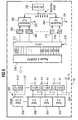
- FIG. 2 shows the components of a network frame NR transmitted in the data transmission network 10 according to FIG. 1.
- the network frames NR are transmitted with a fixed frame frequency fR, so that a fixed frame duration RD results.
- Each transmitted network frame NR has a precisely specified number of bit positions which are transmitted according to a specified bit frequency fB, for example 155.52 Mbps (million bits per second) with 121 5 bit positions per network frame NR.
- the network frame NR contains a synchronization part 60, which to determine the exact start of the network frame NR serves. Time follows after the synchronization part 60 Command part 62, in which commands according to a command language between the user units 14 to 26 and the control unit 12 (see FIG. 1) can be exchanged. Command section 62 is also used when a user unit 14 to 26 (cf. FIG. 1) a new user channel is requested.
- the command part 62 is followed by a designation data word 64, in which seven bit positions c to identify one of 128 possible channels are used and two more Bit positions s to designate one of four different ones Sub-cycles UZ1 to UZ4 is used.
- the sub-cycles UZ1 to UZ4 are part of a main cycle HZ for changing the Transmission parameters in the data transmission network 10 (see FIG. 1).
- the main cycle HZ and the sub-cycles UZ1 to UZ4 are explained in more detail below with reference to FIG. 5.
- the network frame also contains a payload 68 of constant length.
- a first Part 70 of the user data part 68 contains user data, which are transmitted via one of the user channels K0 to K127. Depending on the number of user channels K0 to K127 and the number of bit positions used is part 70 different lengths.
- a remaining part 72 of the user data part 68 is in contrast for connection-oriented transmission in part 70 for a connectionless transmission of user data in one the known packet transmission methods used, e.g. ATM (Asynchronous Transfer Mode).
- ATM Asynchronous Transfer Mode
- Unused channels have a length of zero bits, so that in extreme cases, if none of the channels is used, the Entire user data part 68 for transmission in packet mode can be used. With increasing size of part 70 for the useful channels K0 to K127 reduce the proportion of Part 72.
- Fig. 3 shows three time profiles 100, 120 and 140, the one start common time t0.
- the main cycle HZ the consists of the four sub-cycles UZ for 128 channels each, requires a total of 512 network frames NR.
- the time between one Pulse 102 of the course of time 100 and a pulse 104 of the Time course 100 at a time t6 corresponds exactly to that Time for the transmission of 512 network frames NR.
- Has a considered useful channel the length of one bit position, and is a user frame BR is thirty-two bit positions long, so a single user frame BR through thirty-two network frames NR transmitted.
- a pulse 122 of the time history 120 for Time t0 marks the beginning of a first user frame BR1.
- a sixteenth user frame BR16 starting at one after the Time t3 lying time t5 (cf. pulse 128 of the Time course 120)
- 512 network frames NR have already been transmitted been.
- a new user frame BR17 begins Time t6, cf. Pulse 130 of timing 120.
- On Offset between the start of the next user frame BR17 and the beginning of the main cycle HZ does not occur.
- a user frame BR1 ' has on the other hand, forty-eight bit positions, so that forty-eight Network frame used to transmit the user frame BR1 ' will.
- the first user frame BR1 ' is from the time transmitted from t0 to a time t2, which lies between the time t1 and the time t3.
- the Transmission of the first bit of the second user frame BR2 ' is determined by a pulse 144 of the time course 140 at the time shown t2.
- a pulse 146 at a time t4 which lies between the times t3 and t5, characterizes the Start of the third user frame BR3 '.
- an offset occurs at time course 140 of sixteen network frames NR within a main cycle HZ on.
- the offset can be adjusted using the modulo operation calculate by the number of network frames NR per main cycle HZ by the product of the number of bit positions in one User frame BR 'and that used in the relevant user channel Calculate the number of bit positions.
- the offset must be known at least in the user unit 14 to 26 in which the channel in question is accessed so that the data transmission can be carried out without errors.
- FIG. 4 shows two time profiles 160 and 180 for representing the temporal sequence of user frames BR in the case of the passage of time 160 to the device and in the case of the course of time 180 from Device which is connected to the user unit 20 (see FIG. 1) is.
- the device is switched on the user unit 20 signals with the aid of a synchronizing pulse 162, that a user frame BRa has been provided.
- the transmission protocol of the device is set so that a user frame with an offset of X bit positions from the device BR6 is provided.
- the user unit 20 can thus receive the user frame BRb at a time t2 'and edit for further transfer.
- the offset of X Bit positions remain between later times t3 'and t4 ', or between times t5' and t6 '.
- a such an offset occurs, for example, in a transmission from the ISDN protocol (Integrated Services Digital Network) known telecommunications interface S0.
- ISDN protocol Integrated Services Digital Network
- FIG. 5 shows a flow diagram for a method for changing the transmission parameters in the data transmission network 10 according to Fig. 1.
- the method begins in a step 200 with the initial start-up of the data transmission network 10.
- step 202 a channel request is made through the on the user unit 20 connected device generated. This channel requirement is carried out with the help of the command part 62 (see Fig. 2) transmitted to the control unit 12.
- control unit 12 assigns a useful channel to the device. Based on a device-specific device also transmitted in the command section 62 The control unit determines the identification number 12 the appropriate channel length L for the assigned channel (Step 206). In an immediately following step 208 the determined channel length L is added to a list, e.g. commitment entered by memory registers.
- the control unit 12 determines in one step 210 the user frame length LB intended for the device, which is also saved in a list (step 212).
- the user unit determines 12 the modulo offset, which has already been explained with reference to FIG. 3 above has been. This modulo offset is also in the list saved (step 216). The premature calculation of the Modulo offsets and thus their storage can be omitted, if the modulo offset e.g. through a digital Switching off for the respective channel in a very short time the channel length, the user frame length and the number of Network frame NR is calculated per cycle before it is then transmitted becomes.
- Offset LB - (CL * L) MOD LB, where CL is the number of network frames NR in a main cycle HZ explained below.
- the control unit 12 also determines in a step 218 the offset already explained with reference to FIG. 4 above between user frames during input and output in or out of the device. This offset is also in one List saved (step 220).
- a counter for the channel number Kn is set to the value zero. Then a step 224 is carried out.
- step 224 the control unit 12 takes from the list for the channel length L, the channel length L of the useful channel Kn, whose channel number Kn is currently contained in the channel counter.
- a network frame NR is sent in which in the designation part 64 the channel with the current one Channel number Kn is designated and in the in the parameter data word 66 (see FIG. 2) the channel length L of the designated Channel Kn is specified.
- the two bit positions also denote s in the designation data word 64 (see FIG. 2) the first Subcycle UZ1.
- a Step 228 executed.
- step 228 it is checked whether the channel counter has a value which is less than 128, i.e. the total number of usable Channels. If this is the case, immediately after the Step 228 is a step 230 in which the channel counter changes the value "1" is increased. Then the procedure in Step 224 continues.
- the process is in the sub-cycle UZ1, which the Contains steps 224 to 230 and is only ended when in Step 228 determines that the channel length L was transmitted for all user channels.
- the next sub-cycle follows immediately after step 228 UZ2.
- the subcycle UZ2 is shown in FIG. 5 in simplified form by a block 232, which has a structure that corresponds to the structure of steps 224 to 230.
- the channel number Kn contained in the designation data word 64 in bit positions c (cf. FIG. 2) is increased from network frame NR to network frame NR by the value “1”.
- the subcycle UZ2 is designated in the bit positions s of the designation data word 64.
- the parameter data word 66 (cf. FIG. 2), the user frame lengths LB belonging to the channel Kn designated in the designation data word 64 are specified.
- sub-cycle UZ2 After 128 transmitted network frames NR, sub-cycle UZ2 has ended and the method is continued with sub-cycle UZ3, which is shown in block 234.
- sub-cycle UZ3 128 network frames NR are again transmitted, in each of which one of the user channels Kn and the modulo result taken from the corresponding list for this user channel Kn are transmitted.
- the subcycle UZ3 is identified in the bit positions s of the designation data word 64 (cf. FIG. 2). After 128 transmitted network frames NR, sub-cycle UZ3 has ended and the method is continued with sub-cycle UZ4, cf. Block 236.
- 128 subframes NR are transmitted in subcycle UZ4, in each of which in the designation data word 64 one of the useful channels Kn is designated. Located in parameter data word 66 the offset belonging to the designated service channel Kn, the was determined in step 218. After 128 transmitted network frames NR in subcycle UZ4, this is ended and the procedure continued in a step 238.
- step 2308 the method is ended by the transmitted Transmission parameters used for the transmission will.
- a change of the function as counter Bit positions c in the designation data word 64 uses the value "0".
- the user units 14 to 26 (cf. Fig. 1) recognize by jumping around this counter value that the transmitted transmission parameters now for the transmission are to be used.
- step 236 follows a step 240 instead of step 238.
- step 240 it is checked whether changes in the transmission parameters are required if, for example, another device Useful channel or a device needs its useful channel again releases. If changes are not required, the following follows the step 240 immediately the step 222. Are changes, however required, then follows after step 240 Step 204.
- Fig. 6 shows a schematic representation of the change the transmission parameters used in the user unit 20 Assemblies.
- a register set 250 there are 128 register locations 6, four register locations 252 to 258 are shown.
- Register space 252, 254 and 256 is used to store the in the first subcycle UZ1 Control unit 12 transmitted channel length L0, L1 or L2 of the Useful channel K0, K1 or K2 used.
- register number 258 the length L127 of the user channel K127 is saved.
- An adder ADD0 arranged, which the start address A1 of the user channel K1 in Network frame NR calculated. With the help of another entrance 260 of the adder ADD0 can the start address A0 des User channel K0 can be freely specified.
- the address A1 on Output of the adder ADD0 serves as the basis for the Calculation of the start address of the following user channel K2 in Network frame no.
- the address value A1 in an adder ADD1 the channel length L1 of the stored in register position 254 User channel K1 added to address A1.
- the start address of the user channel K2 is output.
- further adders ADD2 to calculate ADD127 the start address of the user channels K3 to K127.
- each register place 252 to 258 via a line in the respective register number 252 to 258 stored channel length L0 to L127 tapped so that they is available for further processing.
- the registry 250 and the adders ADD0 to ADD127 are in the right part of the 6 in a register set adder block 270 summarized, which the outputs A0 to A127 and L0 to L127 has an electrical input Switch block 272 are connected.
- Switch block 272 switches the output lines A0 to A127 and L0 to L127 of register adder block 270 when a control signal is present on a line 274 to register locations 276 to 282 for storing the addresses A0 to A127 or the lengths L0 to L127 through. This switching becomes the end of the Main cycle HZ carried out.
- a comparator With the exit of one of the Register channels 276 to 282 belonging to user channels K0 to K127 a comparator is connected, of which in the Fig. 6, comparators 284 and 286 are shown.
- the comparator 284 is with the register space 276 for the Address A0 of the utility channel K0 and with register space 278 connected for the length L0 of the useful channel K0.
- the comparator 286 is analogous to register space 280 for the address A127 of the K127 user channel and with register space 282 for the length L127 of the utility channel K127 is connected.
- the comparator 284 compares address A0 with one through a bit counter 288 for counting the bit positions already transmitted in the Network frame NR generated bit address. As soon as the bit counter 288 reached an address that matches address A0, becomes at the output of the comparator on a line 290 Control signal for a multiplexer generated that long is effective until the bit counter 288 reaches an address which corresponds to an address A0 + L0.
- the signal on the Line 290 ensures that in the network frame NR Also useful data of the device transmitting on channel K0 really to the designated bit positions in the network frame NR arrive.
- Comparator 228 compares the address of bit counter 288 with the address A127 and generates on a line 292 Control signal if bit counter 288 reaches address A127.
- the control signal on line 292 remains as long effective until the bit counter 288 reaches an address which corresponds to the sum of the address 127 and the length L127.
- the signal on line 292 ensures that a demultiplexer exactly what data is switched through to the device receives in the useful channel K127.
Landscapes
- Engineering & Computer Science (AREA)
- Computer Networks & Wireless Communication (AREA)
- Signal Processing (AREA)
- Communication Control (AREA)
Applications Claiming Priority (2)
| Application Number | Priority Date | Filing Date | Title |
|---|---|---|---|
| DE19650525 | 1996-12-05 | ||
| DE19650525 | 1996-12-05 |
Publications (2)
| Publication Number | Publication Date |
|---|---|
| EP0847165A1 true EP0847165A1 (fr) | 1998-06-10 |
| EP0847165B1 EP0847165B1 (fr) | 2007-01-24 |
Family
ID=7813760
Family Applications (1)
| Application Number | Title | Priority Date | Filing Date |
|---|---|---|---|
| EP97121122A Expired - Lifetime EP0847165B1 (fr) | 1996-12-05 | 1997-12-01 | Réseau de transmission de données digitales et méthode pour activer un réseau de transmission de données |
Country Status (3)
| Country | Link |
|---|---|
| US (1) | US6028864A (fr) |
| EP (1) | EP0847165B1 (fr) |
| DE (1) | DE59712802D1 (fr) |
Cited By (2)
| Publication number | Priority date | Publication date | Assignee | Title |
|---|---|---|---|---|
| WO2004034639A2 (fr) * | 2002-10-08 | 2004-04-22 | Siemens Aktiengesellschaft | Procede de transformation d'un procede pour le fonctionnement d'un reseau ainsi que des abonnes pour appliquer le procede |
| WO2007073862A1 (fr) * | 2005-12-15 | 2007-07-05 | Beckhoff Automation Gmbh | Procede, reseau de communication et unite de commande permettant une transmission cyclique de donnees |
Families Citing this family (56)
| Publication number | Priority date | Publication date | Assignee | Title |
|---|---|---|---|---|
| FI970266A (fi) * | 1997-01-22 | 1998-07-23 | Nokia Telecommunications Oy | Menetelmä solukkoradiojärjestelmän ohjauskanavien kantaman pidentämiseksi ja solukkoradiojärjestelmä |
| US6618366B1 (en) * | 1997-12-05 | 2003-09-09 | The Distribution Systems Research Institute | Integrated information communication system |
| GB2382748A (en) * | 2001-11-28 | 2003-06-04 | Ipwireless Inc | Signal to noise plus interference ratio (SNIR) estimation with corection factor |
| US8655490B2 (en) * | 2008-10-27 | 2014-02-18 | Lennox Industries, Inc. | System and method of use for a user interface dashboard of a heating, ventilation and air conditioning network |
| US20100107072A1 (en) * | 2008-10-27 | 2010-04-29 | Lennox Industries Inc. | System and method of use for a user interface dashboard of a heating, ventilation and air conditioning network |
| US20100106957A1 (en) * | 2008-10-27 | 2010-04-29 | Lennox Industries Inc. | Programming and configuration in a heating, ventilation and air conditioning network |
| US8433446B2 (en) * | 2008-10-27 | 2013-04-30 | Lennox Industries, Inc. | Alarm and diagnostics system and method for a distributed-architecture heating, ventilation and air conditioning network |
| US8694164B2 (en) * | 2008-10-27 | 2014-04-08 | Lennox Industries, Inc. | Interactive user guidance interface for a heating, ventilation and air conditioning system |
| US8295981B2 (en) * | 2008-10-27 | 2012-10-23 | Lennox Industries Inc. | Device commissioning in a heating, ventilation and air conditioning network |
| US8855825B2 (en) | 2008-10-27 | 2014-10-07 | Lennox Industries Inc. | Device abstraction system and method for a distributed-architecture heating, ventilation and air conditioning system |
| US9152155B2 (en) * | 2008-10-27 | 2015-10-06 | Lennox Industries Inc. | Device abstraction system and method for a distributed-architecture heating, ventilation and air conditioning system |
| US8548630B2 (en) | 2008-10-27 | 2013-10-01 | Lennox Industries, Inc. | Alarm and diagnostics system and method for a distributed-architecture heating, ventilation and air conditioning network |
| US8442693B2 (en) | 2008-10-27 | 2013-05-14 | Lennox Industries, Inc. | System and method of use for a user interface dashboard of a heating, ventilation and air conditioning network |
| US8463443B2 (en) * | 2008-10-27 | 2013-06-11 | Lennox Industries, Inc. | Memory recovery scheme and data structure in a heating, ventilation and air conditioning network |
| US20100106326A1 (en) * | 2008-10-27 | 2010-04-29 | Lennox Industries Inc. | Communication protocol system and method for a distributed-architecture heating, ventilation and air conditioning network |
| US8560125B2 (en) * | 2008-10-27 | 2013-10-15 | Lennox Industries | Communication protocol system and method for a distributed-architecture heating, ventilation and air conditioning network |
| US8452456B2 (en) * | 2008-10-27 | 2013-05-28 | Lennox Industries Inc. | System and method of use for a user interface dashboard of a heating, ventilation and air conditioning network |
| US8255086B2 (en) * | 2008-10-27 | 2012-08-28 | Lennox Industries Inc. | System recovery in a heating, ventilation and air conditioning network |
| US9377768B2 (en) * | 2008-10-27 | 2016-06-28 | Lennox Industries Inc. | Memory recovery scheme and data structure in a heating, ventilation and air conditioning network |
| US8600559B2 (en) * | 2008-10-27 | 2013-12-03 | Lennox Industries Inc. | Method of controlling equipment in a heating, ventilation and air conditioning network |
| US20100106312A1 (en) * | 2008-10-27 | 2010-04-29 | Lennox Industries Inc. | Alarm and diagnostics system and method for a distributed-architecture heating, ventilation and air conditioning network |
| US8994539B2 (en) * | 2008-10-27 | 2015-03-31 | Lennox Industries, Inc. | Alarm and diagnostics system and method for a distributed-architecture heating, ventilation and air conditioning network |
| US9432208B2 (en) | 2008-10-27 | 2016-08-30 | Lennox Industries Inc. | Device abstraction system and method for a distributed architecture heating, ventilation and air conditioning system |
| US8239066B2 (en) * | 2008-10-27 | 2012-08-07 | Lennox Industries Inc. | System and method of use for a user interface dashboard of a heating, ventilation and air conditioning network |
| US8762666B2 (en) * | 2008-10-27 | 2014-06-24 | Lennox Industries, Inc. | Backup and restoration of operation control data in a heating, ventilation and air conditioning network |
| US20100106810A1 (en) * | 2008-10-27 | 2010-04-29 | Lennox Industries Inc. | Communication protocol system and method for a distributed-architecture heating, ventilation and air conditioning network |
| US8615326B2 (en) * | 2008-10-27 | 2013-12-24 | Lennox Industries Inc. | System and method of use for a user interface dashboard of a heating, ventilation and air conditioning network |
| US9268345B2 (en) * | 2008-10-27 | 2016-02-23 | Lennox Industries Inc. | System and method of use for a user interface dashboard of a heating, ventilation and air conditioning network |
| US8977794B2 (en) * | 2008-10-27 | 2015-03-10 | Lennox Industries, Inc. | Communication protocol system and method for a distributed-architecture heating, ventilation and air conditioning network |
| US9651925B2 (en) | 2008-10-27 | 2017-05-16 | Lennox Industries Inc. | System and method for zoning a distributed-architecture heating, ventilation and air conditioning network |
| US9325517B2 (en) * | 2008-10-27 | 2016-04-26 | Lennox Industries Inc. | Device abstraction system and method for a distributed-architecture heating, ventilation and air conditioning system |
| US8452906B2 (en) | 2008-10-27 | 2013-05-28 | Lennox Industries, Inc. | Communication protocol system and method for a distributed-architecture heating, ventilation and air conditioning network |
| US8725298B2 (en) * | 2008-10-27 | 2014-05-13 | Lennox Industries, Inc. | Alarm and diagnostics system and method for a distributed architecture heating, ventilation and conditioning network |
| US8437877B2 (en) * | 2008-10-27 | 2013-05-07 | Lennox Industries Inc. | System recovery in a heating, ventilation and air conditioning network |
| US8543243B2 (en) * | 2008-10-27 | 2013-09-24 | Lennox Industries, Inc. | System and method of use for a user interface dashboard of a heating, ventilation and air conditioning network |
| US8798796B2 (en) * | 2008-10-27 | 2014-08-05 | Lennox Industries Inc. | General control techniques in a heating, ventilation and air conditioning network |
| US8661165B2 (en) * | 2008-10-27 | 2014-02-25 | Lennox Industries, Inc. | Device abstraction system and method for a distributed architecture heating, ventilation and air conditioning system |
| US8788100B2 (en) | 2008-10-27 | 2014-07-22 | Lennox Industries Inc. | System and method for zoning a distributed-architecture heating, ventilation and air conditioning network |
| US8655491B2 (en) * | 2008-10-27 | 2014-02-18 | Lennox Industries Inc. | Alarm and diagnostics system and method for a distributed architecture heating, ventilation and air conditioning network |
| US9261888B2 (en) | 2008-10-27 | 2016-02-16 | Lennox Industries Inc. | System and method of use for a user interface dashboard of a heating, ventilation and air conditioning network |
| US8802981B2 (en) * | 2008-10-27 | 2014-08-12 | Lennox Industries Inc. | Flush wall mount thermostat and in-set mounting plate for a heating, ventilation and air conditioning system |
| US8600558B2 (en) * | 2008-10-27 | 2013-12-03 | Lennox Industries Inc. | System recovery in a heating, ventilation and air conditioning network |
| US8437878B2 (en) * | 2008-10-27 | 2013-05-07 | Lennox Industries Inc. | Alarm and diagnostics system and method for a distributed architecture heating, ventilation and air conditioning network |
| US8892797B2 (en) * | 2008-10-27 | 2014-11-18 | Lennox Industries Inc. | Communication protocol system and method for a distributed-architecture heating, ventilation and air conditioning network |
| US9678486B2 (en) * | 2008-10-27 | 2017-06-13 | Lennox Industries Inc. | Device abstraction system and method for a distributed-architecture heating, ventilation and air conditioning system |
| US8564400B2 (en) * | 2008-10-27 | 2013-10-22 | Lennox Industries, Inc. | Communication protocol system and method for a distributed-architecture heating, ventilation and air conditioning network |
| US8874815B2 (en) * | 2008-10-27 | 2014-10-28 | Lennox Industries, Inc. | Communication protocol system and method for a distributed architecture heating, ventilation and air conditioning network |
| US8463442B2 (en) * | 2008-10-27 | 2013-06-11 | Lennox Industries, Inc. | Alarm and diagnostics system and method for a distributed architecture heating, ventilation and air conditioning network |
| US8774210B2 (en) | 2008-10-27 | 2014-07-08 | Lennox Industries, Inc. | Communication protocol system and method for a distributed-architecture heating, ventilation and air conditioning network |
| US8352081B2 (en) | 2008-10-27 | 2013-01-08 | Lennox Industries Inc. | Communication protocol system and method for a distributed-architecture heating, ventilation and air conditioning network |
| US9632490B2 (en) | 2008-10-27 | 2017-04-25 | Lennox Industries Inc. | System and method for zoning a distributed architecture heating, ventilation and air conditioning network |
| US8744629B2 (en) * | 2008-10-27 | 2014-06-03 | Lennox Industries Inc. | System and method of use for a user interface dashboard of a heating, ventilation and air conditioning network |
| US8352080B2 (en) * | 2008-10-27 | 2013-01-08 | Lennox Industries Inc. | Communication protocol system and method for a distributed-architecture heating, ventilation and air conditioning network |
| USD648641S1 (en) | 2009-10-21 | 2011-11-15 | Lennox Industries Inc. | Thin cover plate for an electronic system controller |
| USD648642S1 (en) | 2009-10-21 | 2011-11-15 | Lennox Industries Inc. | Thin cover plate for an electronic system controller |
| US8260444B2 (en) | 2010-02-17 | 2012-09-04 | Lennox Industries Inc. | Auxiliary controller of a HVAC system |
Citations (3)
| Publication number | Priority date | Publication date | Assignee | Title |
|---|---|---|---|---|
| US4814761A (en) * | 1986-03-07 | 1989-03-21 | Hitachi, Ltd. | Method and apparatus for communication control in loop communication network |
| EP0462349A1 (fr) * | 1990-06-21 | 1991-12-27 | International Business Machines Corporation | Système de communication en anneau à large bande et méthode de commande d'accès |
| US5090029A (en) * | 1986-09-05 | 1992-02-18 | Hitachi, Ltd. | Data communication method and apparatus |
Family Cites Families (5)
| Publication number | Priority date | Publication date | Assignee | Title |
|---|---|---|---|---|
| FI79772C (fi) * | 1988-06-23 | 1990-02-12 | Smartset Oy | Foerfarande och anordning foer styrning av eleffekt. |
| JPH0234059A (ja) * | 1988-07-25 | 1990-02-05 | Mitsubishi Electric Corp | ノード装置の処理方式 |
| US5425022A (en) * | 1989-06-16 | 1995-06-13 | British Telecommunications Public Limited Company | Data switching nodes |
| FI95184C (fi) * | 1992-04-16 | 1995-12-27 | Tapio Marttinen | Menetelmä digitaalisen tiedon siirtämiseksi |
| DE19604245C2 (de) * | 1996-02-06 | 2000-07-06 | Siemens Ag | Verfahren zum Übertragen von Zeitmultiplexkanalform-Digitalsignalen über eine ATM-Übertragungseinrichtung |
-
1997
- 1997-12-01 DE DE59712802T patent/DE59712802D1/de not_active Expired - Fee Related
- 1997-12-01 EP EP97121122A patent/EP0847165B1/fr not_active Expired - Lifetime
- 1997-12-03 US US08/984,541 patent/US6028864A/en not_active Expired - Fee Related
Patent Citations (3)
| Publication number | Priority date | Publication date | Assignee | Title |
|---|---|---|---|---|
| US4814761A (en) * | 1986-03-07 | 1989-03-21 | Hitachi, Ltd. | Method and apparatus for communication control in loop communication network |
| US5090029A (en) * | 1986-09-05 | 1992-02-18 | Hitachi, Ltd. | Data communication method and apparatus |
| EP0462349A1 (fr) * | 1990-06-21 | 1991-12-27 | International Business Machines Corporation | Système de communication en anneau à large bande et méthode de commande d'accès |
Non-Patent Citations (1)
| Title |
|---|
| T.HAMADA ET AL.: "Trunk Network: Integrated LAN for Distributed Computer Control", IEEE/IEICE GLOBAL TELECOMMUNICATIONS CONFERENCE, vol. 2, 15 November 1987 (1987-11-15) - 18 November 1987 (1987-11-18), TOKYO (JAPAN), pages 1427 - 1431, XP002058853 * |
Cited By (6)
| Publication number | Priority date | Publication date | Assignee | Title |
|---|---|---|---|---|
| WO2004034639A2 (fr) * | 2002-10-08 | 2004-04-22 | Siemens Aktiengesellschaft | Procede de transformation d'un procede pour le fonctionnement d'un reseau ainsi que des abonnes pour appliquer le procede |
| WO2004034639A3 (fr) * | 2002-10-08 | 2004-08-26 | Siemens Ag | Procede de transformation d'un procede pour le fonctionnement d'un reseau ainsi que des abonnes pour appliquer le procede |
| WO2007073862A1 (fr) * | 2005-12-15 | 2007-07-05 | Beckhoff Automation Gmbh | Procede, reseau de communication et unite de commande permettant une transmission cyclique de donnees |
| JP2009519638A (ja) * | 2005-12-15 | 2009-05-14 | ベックホフ オートメーション ゲーエムベーハー | データのサイクリック伝送のための方法、通信ネットワーク、及び制御装置 |
| JP4691601B2 (ja) * | 2005-12-15 | 2011-06-01 | ベックホフ オートメーション ゲーエムベーハー | データのサイクリック伝送のための方法、通信ネットワーク、及び制御装置 |
| US10193705B2 (en) | 2005-12-15 | 2019-01-29 | Beckhoff Automation Gmbh | Method, communication network, and control unit for the cyclical transmission of data |
Also Published As
| Publication number | Publication date |
|---|---|
| US6028864A (en) | 2000-02-22 |
| DE59712802D1 (de) | 2007-03-15 |
| EP0847165B1 (fr) | 2007-01-24 |
Similar Documents
| Publication | Publication Date | Title |
|---|---|---|
| EP0847165B1 (fr) | Réseau de transmission de données digitales et méthode pour activer un réseau de transmission de données | |
| DE60121698T2 (de) | Verfahren zum Ausstrahlen von Systemnachrichten in einem asynchronen mobilen Kommunikationssystem | |
| EP0419959B1 (fr) | Circuit pour contrÔler le respet de débits préétablis lors de la transmission de cellules de données | |
| WO2019081230A1 (fr) | Procédé de transmission de données et réseau de communication | |
| EP2115948A1 (fr) | Procédé et équipement de transmission optimisée des données entre un dispositif de commande et plusieurs appareils de terrain | |
| DE4104601A1 (de) | Empfangsdatenverarbeitungsanlage | |
| DE60316758T2 (de) | System zur Synchronisierung von Befehlen, sowie ein Verfahren, ein Steuerungsgerät und ein Zielgerät für dasselbe System | |
| EP3378212B1 (fr) | Procédé pour faire fonctionner un réseau de communication, dispositif de commande et dispositif de traitement de données | |
| DE10200201A1 (de) | Zyklusbasiertes zeitgesteuertes Kommunikationssystem | |
| DE102011015966A1 (de) | Automatisierungssystem | |
| EP1841285A1 (fr) | Prothèse auditive avec datalogging binaural et procédé correspondant | |
| EP0010600B1 (fr) | Procédé de transmission codée de signaux de parole, utilisation du procédé dans un système de transmission multiplex à division de temps et dispositif pour la mise en oeuvre de ce procédé | |
| DE19751267A1 (de) | Verfahren zum Bestimmen der Prioritätsreihenfolge im Datenverkehr auf einem Netzwerk | |
| EP0985320B1 (fr) | Dispositif de multiplexage de signaux videos | |
| EP1436950B1 (fr) | Dispositif abonne pour systeme de communication hautes performances | |
| EP1430670A1 (fr) | Procede pour l'exploitation d'un systeme de communication cyclique isochrone | |
| DE10307424A1 (de) | Datenvermittlungsvorrichtung und Multiplex-Kommunikationssysteme | |
| WO1999021393A1 (fr) | Module pour traitement eag de cellules mta d'un flux de cellules sur des liaisons virtuelles | |
| DE10308953A1 (de) | Kommunikation in einem Datennetz | |
| EP0584387B1 (fr) | Procédé et circuit pour surveiller l'agencement de cellules pendant la transmission des cellules d'information | |
| WO2006114391A1 (fr) | Systeme de communication | |
| EP2203991B1 (fr) | Système de radiocommunication, appareil de coordination et terminal de communication | |
| WO2021105132A1 (fr) | Procédé de communication de données entre abonnés dans un réseau d'automatisation, abonné maître pour un réseau d'automatisation et réseau d'automatisation | |
| DE602004009382T2 (de) | Verfahren und anordnung zur planung der verkehrsabfolge in einem telekommunikationssystem | |
| DE2558980B2 (de) | Digitalschalteinheit für Informationsabschnitte |
Legal Events
| Date | Code | Title | Description |
|---|---|---|---|
| PUAI | Public reference made under article 153(3) epc to a published international application that has entered the european phase |
Free format text: ORIGINAL CODE: 0009012 |
|
| AK | Designated contracting states |
Kind code of ref document: A1 Designated state(s): DE FR GB IT |
|
| AX | Request for extension of the european patent |
Free format text: AL;LT;LV;MK;RO;SI |
|
| 17P | Request for examination filed |
Effective date: 19980720 |
|
| AKX | Designation fees paid |
Free format text: DE FR GB IT |
|
| RBV | Designated contracting states (corrected) |
Designated state(s): DE FR GB IT |
|
| GRAP | Despatch of communication of intention to grant a patent |
Free format text: ORIGINAL CODE: EPIDOSNIGR1 |
|
| GRAS | Grant fee paid |
Free format text: ORIGINAL CODE: EPIDOSNIGR3 |
|
| GRAA | (expected) grant |
Free format text: ORIGINAL CODE: 0009210 |
|
| AK | Designated contracting states |
Kind code of ref document: B1 Designated state(s): DE FR GB IT |
|
| REG | Reference to a national code |
Ref country code: GB Ref legal event code: FG4D Free format text: NOT ENGLISH |
|
| GBT | Gb: translation of ep patent filed (gb section 77(6)(a)/1977) |
Effective date: 20070215 |
|
| REF | Corresponds to: |
Ref document number: 59712802 Country of ref document: DE Date of ref document: 20070315 Kind code of ref document: P |
|
| ET | Fr: translation filed | ||
| PLBE | No opposition filed within time limit |
Free format text: ORIGINAL CODE: 0009261 |
|
| STAA | Information on the status of an ep patent application or granted ep patent |
Free format text: STATUS: NO OPPOSITION FILED WITHIN TIME LIMIT |
|
| 26N | No opposition filed |
Effective date: 20071025 |
|
| PGFP | Annual fee paid to national office [announced via postgrant information from national office to epo] |
Ref country code: IT Payment date: 20071219 Year of fee payment: 11 |
|
| PGFP | Annual fee paid to national office [announced via postgrant information from national office to epo] |
Ref country code: GB Payment date: 20071213 Year of fee payment: 11 Ref country code: FR Payment date: 20071219 Year of fee payment: 11 |
|
| PG25 | Lapsed in a contracting state [announced via postgrant information from national office to epo] |
Ref country code: DE Free format text: LAPSE BECAUSE OF NON-PAYMENT OF DUE FEES Effective date: 20080701 |
|
| GBPC | Gb: european patent ceased through non-payment of renewal fee |
Effective date: 20081201 |
|
| REG | Reference to a national code |
Ref country code: FR Ref legal event code: ST Effective date: 20090831 |
|
| PG25 | Lapsed in a contracting state [announced via postgrant information from national office to epo] |
Ref country code: GB Free format text: LAPSE BECAUSE OF NON-PAYMENT OF DUE FEES Effective date: 20081201 |
|
| PG25 | Lapsed in a contracting state [announced via postgrant information from national office to epo] |
Ref country code: FR Free format text: LAPSE BECAUSE OF NON-PAYMENT OF DUE FEES Effective date: 20081231 |
|
| PG25 | Lapsed in a contracting state [announced via postgrant information from national office to epo] |
Ref country code: IT Free format text: LAPSE BECAUSE OF NON-PAYMENT OF DUE FEES Effective date: 20081201 |