EP0845843B1 - Schutzvorrichtung für Telephonlinien - Google Patents
Schutzvorrichtung für Telephonlinien Download PDFInfo
- Publication number
- EP0845843B1 EP0845843B1 EP19970402862 EP97402862A EP0845843B1 EP 0845843 B1 EP0845843 B1 EP 0845843B1 EP 19970402862 EP19970402862 EP 19970402862 EP 97402862 A EP97402862 A EP 97402862A EP 0845843 B1 EP0845843 B1 EP 0845843B1
- Authority
- EP
- European Patent Office
- Prior art keywords
- fact
- spring blade
- membrane
- fusible
- cell
- Prior art date
- Legal status (The legal status is an assumption and is not a legal conclusion. Google has not performed a legal analysis and makes no representation as to the accuracy of the status listed.)
- Expired - Lifetime
Links
Images

Classifications
-
- H—ELECTRICITY
- H01—ELECTRIC ELEMENTS
- H01T—SPARK GAPS; OVERVOLTAGE ARRESTERS USING SPARK GAPS; SPARKING PLUGS; CORONA DEVICES; GENERATING IONS TO BE INTRODUCED INTO NON-ENCLOSED GASES
- H01T1/00—Details of spark gaps
- H01T1/14—Means structurally associated with spark gap for protecting it against overload or for disconnecting it in case of failure
-
- H—ELECTRICITY
- H01—ELECTRIC ELEMENTS
- H01T—SPARK GAPS; OVERVOLTAGE ARRESTERS USING SPARK GAPS; SPARKING PLUGS; CORONA DEVICES; GENERATING IONS TO BE INTRODUCED INTO NON-ENCLOSED GASES
- H01T1/00—Details of spark gaps
- H01T1/12—Means structurally associated with spark gap for recording operation thereof
Definitions
- the present invention relates to the field of devices for protection of telephone lines.
- Surge arresters for telephone lines are generally made from three-pole gas spark gaps to allow protection of the two line wires relative to the earth. Most of the time, these components end up short-circuiting report the unavailability of the line on the one hand, and ensure the protection of the terminal on the other hand. This end of life is ensured by an external device on the spark gap.
- the short-circuiting devices used on the commercial surge arresters generally consist of devices thermal which, from a determined temperature, remove the insulation between two of the spark gap electrodes.
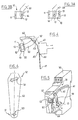
- FIG. 1 there is shown under reference 10 a spark gap conventional gas pipe with three output electrodes 11, 12, 13, and 20 a leaf spring of electrically conductive material connected in permanence at the central electrode 12, but isolated at the origin of the electrodes 11, 13 terminated by respective washers 21, 22 made of material electrically insulating. Heating of the device at the end of its life causes the fusion of the washers 21, 22 of insulation and consequently the contact of the blade 20 with the electrodes 11, 13 to ensure the complete short circuit of the device between the three electrodes 11, 12 and 13.
- the known device illustrated in FIG. 1 gives overall satisfaction with the protection of telephone lines. However, it has a major drawback: it does not allow the formal visualization of the fault.
- line protection devices telephone calls can be found for example in documents: FR-2409616, FR-2466854, FR-2560457, FR-2560458, FR-2659504, FR-2696581, FR-2710793 and FR-2692738.
- the document EP-A-0312729 describes a protection device for telephone line comprising a lightning arrester placed in a main housing of a housing made of thermoplastic material and which comprises in an auxiliary housing separated from the main housing by a fusible membrane, an elastic rider-shaped blade, made of material electrically conductive. In the event of overheating, the fusible membrane is broken and the elastic blade in jumper is likely to short-circuit the surge arrester cell.
- the overvoltage comprises in a box, in series between two terminals of connection, a varistor and a fusible element with, under dependence of the fuse element an indicating means which, mounted movable between a operating position and a fault position, is continuously requested by elastic means towards its defect position.
- the indicating means consists of a tape which, while whole housed in the housing, is slidably mounted longitudinally in this one with on this box, a window thanks to which this ribbon is at least partially visible.
- the present invention now aims to meet the aforementioned problems by proposing a new surge arrester device protection of telephone lines with an end-of-life indicator.
- An important goal is in particular to propose such an adapted device to support the normative tests in force.
- the blade elastic is made of electrically conductive material and is suitable to view the end of life of the device.
- the device according to the present invention according to which the means for retaining under stress the elastic blade is formed of a calibrated fuse membrane, makes it possible to hold the two aforementioned tests. This results in particular from the fact that the dimensioning of the membrane fuse allows to play on the two parameters temperature and time.
- a protective device comprising a housing or cradle 30 which houses a protection cell 10 and supports an elastic blade 40 thus a fusible membrane 50, as indicated previously.
- the cradle 30 can be the subject of numerous variants of production. It preferably corresponds to a classic geometry (by example of width equal to 17.5 mm) standardized to allow sound combination in cabinets and on conventional rails such as rails DIN.
- the lightning protection cell 10 is preferably also classic in itself. It may for example be a gas spark gap tripolar as previously indicated.
- the elastic blade 40 is preferably made of electrically material driver to participate, in combination with contacts 42, 44 electrically conductive carried by the housing 30, has a visualization distance from end of life of the device.
- the elastic blade 40 is held under stress, at rest by the fuse membrane 50.
- the elastic blade 40 is embedded or fixed by other means, to a first of its ends 41 on the case 30.
- the elastic blade 40 is moreover retained at its second end 43 by the fusible membrane 50.
- the latter is fixed by a first end 51 on the lightning protection cell 10, and by a second end 52 on said second end 43 of the elastic blade 40.
- the stress of the elastic blade 40 exerts a force on the traction on the fuse membrane 50.
- the fusible membrane 50 releases the elastic blade 40.
- the elastic blade 40 then occupies a second position as illustrated in broken lines on Figure 2. In this second position, the elastic blade 40 abuts on the aforementioned contacts 42, 44, previously isolated, which allow ensure the end of electrical life of the arrester.
- the elastic blade 40 can also be associated, by its second end 43 has a display piece 60 mounted at displacement, for example in translation on the housing 30. Such a piece of display 60 is more particularly visible in FIG. 5. It can be the subject of numerous embodiments.
- the display part 60 can be associated with two protection cells 10 placed in parallel and each associated with an elastic blade 40 and a fusible membrane 50 respectively.
- the display part 60 is provided with two stages of training finger, illustrated under the general reference 62 in the figure 5, some rigid, others flexible to elastically cross the end 43 of a blade 40.
- Such an arrangement makes it possible to distinguish the cases where 1) the two cells 10 are in service, 2) one of the two cells 10 is disconnected and 3) the two cells 10 are disconnected.
- the amplitude of movement of the display part 60 depends on the number of cells 10 in service. More specifically, at rest, when the two cells 10 are in service, the ends 43 of the blades 40 take support on the rigid stages of the drive fingers of the part 60 of viewing.
- the end 43 of the corresponding blade 40 moves and drives the part 60 of display on a first amplitude.
- the flexible stage of the other drive finger of the part 60 elastically crosses the end 43 of the blade 40 associated with the second cell 10 so that this end 43 of this blade 40 is placed in abutment against said flexible stage.
- the end 43 of the blade 40 in question moves the part 60 on a second amplitude, by requesting the flexible drive stage placed opposite.
- the display part 60 illustrated in FIG. 5 is broadly in accordance with the provisions described in the patent application FR-94 14586 of 5/12/94.
- this display part 60 is provided with a flap 64 designed to be moved next to a window formed in the housing 60 during the release of the elastic blade 40.
- the device according to the present invention can further include an optical barrier detection system for order a fault display by remote monitoring.
- the elastic blade 40 may include an opaque flap 45 positioned to modify the state of an optical curtain according to whether the blade 40 occupies the original position maintained by the fusible diaphragm 50 or is moved after rupture of the membrane 50.
- the flap 45 is formed by folding a portion of the elastic blade 40 at 90 ° from its plane way.
- the flap 45 can be adapted to release the curtain optical in the original position of the elastic blade 40, but on the contrary obscure it when the membrane 50 releases the elastic blade 40.
- the optical curtain can be defined by a channel 31 formed in the housing 30 or a series of boxes 30 attached, between an optical transmitter and a receiver associated optics.
- the fusible membrane 50 is made of a material thermoplatique.
- the fusible membrane 50 can be made of polycarbonate and have a width of the order of 3 to 5mm and a thickness of the order of 375 to 500 ⁇ m. Its length is for example of around 20mm.
- this membrane 50 illustrated by way of nonlimiting example in FIG. 6 includes an orifice 53 at its first end 51 for engagement on the pin 14, and a oblong light 54 at its second end 52 for engagement on the elastic blade 40. Furthermore, this membrane 50 which has edges longitudinal straight is generally flared towards its second end 52.
- the device according to the present invention with an end-of-life indicator eliminates all power supply for display of end-of-life protection, even if the site's telecommunications equipment is no longer supplied. This represents a very important advantage compared to the devices existing classics that previously required an electrical protection test after finding the faulty telephone line among all the site lines.
- FIG. 3A a first variant according to the present invention comprising a spark gap with three-pole gas 10, the end 51 of the fusible membrane 50 being linked to a pin 14 placed on the central electrode 12.
- the membrane 50 it is indeed preferable to bond the membrane 50 to the electrode central 12 which is the one that heats the most in the event of a failure.
- the end 51 of the membrane 50 could be linked to one of the end electrodes 11 or 13.
- FIG. 3B illustrates another variant of the protection 10 according to the present invention formed by a gas spark gap 10 bipolar, with two electrodes 11, 12, the end 51 of the membrane fuse 50 being linked to a pin 14 placed on one of the electrodes 12.
- membrane should not be understood in a sense limiting. In practice, the invention encompasses any equivalent means based on ribbon or link capable of initially keeping the elastic blade under stress 40.
- the protection device according to the present invention can be completed by a blade 20 in electrically conductive material, conventional, of the type described previously with regard to FIG. 1 to connect the various poles of cell 10 in the event of failure, as shown diagrammatically in the figure 4.
Landscapes
- Fuses (AREA)
- Devices For Indicating Variable Information By Combining Individual Elements (AREA)
Claims (11)
- Schutzvorrichtung für Telephonlinien mit
einer Blitzableitungszelle (10), einer elastischen Feder (40), die unter Spannung gehalten wird, und einer Sicherungsmembran (50) aus einem thermoplastischen Material, das dazu geeignet ist, die elastischen Feder (40) unter Spannung zu halten und diese freizugeben, wenn die Überspannungsschutzzelle (10) eine vorgegebene Temperatur erreicht,
dadurch gekennzeichnet, dass
die elastische Feder (40) mit einem ersten Ende (41) an einem Gehäuse (30) befestigt ist und mit ihrem zweiten Ende (43) durch die Sicherungsmembran (50) gehalten wird, wobei die Sicherungsmembran (50) einen Zug ausübt, um die elastische Feder (40) unter Spannung zu halten, indem ein erstes Ende (51) an der Überspannungsschutzzelle (50) befestigt ist und ein zweites Ende (52) an dem zweiten Ende (43) der elastischen Feder (40) befestigt ist, wobei die elastischen Feder (40) so ausgelegt ist, dass Vorrichtungen (42, 44; 60) zum Anzeigen der Zerstörung aktiviert werden, wenn sie durch die Sicherungsmembran (50) freigegeben wird. - Schutzvorrichtung nach Anspruch 1,
dadurch gekennzeichnet, dass
die elastische Feder (40) aus elektrisch leitfähigem Material hergestellt ist und gegenüber elektrischen Kontakten (42, 44) angeordnet ist, so dass sich der Zustand der Verbindung zwischen diesen verändert, wenn die elastische Feder (40) nach Schmelzen der Sicherungsmembran (50) freigegeben wird, um die Zerstörung der Vorrichtung anzuzeigen. - Schutzvorrichtung nach Anspruch 1 oder 2,
dadurch gekennzeichnet, dass
die Sicherungsmembran (50) aus Polycarbonat besteht. - Schutzvorrichtung nach einem der Ansprüche 1 bis 3,
dadurch gekennzeichnet, dass
die Sicherungsmembran (50) eine Breite in der Ordnung von 3 bis 5 mm und eine Dicke in der Ordnung von 375 bis 500 µm aufweist. - Schutzvorrichtung nach einem der Ansprüche 1 bis 4,
dadurch gekennzeichnet, dass
die elastische Feder (40) mit einem beweglichen Anzeigeteil zusammenwirkt. - Schutzvorrichtung nach einem der Ansprüche 1 bis 5,
dadurch gekennzeichnet, dass
die Ableitungszelle (10) aus einem dreipoligen Gasentladungsableiter besteht. - Schutzvorrichtung nach Anspruch 6,
dadurch gekennzeichnet, dass
die Sicherungsmembran (50) gegen die Zentralelektrode (12) des dreipoligen Gasentladungsableiters (10) drückt. - Schutzvorrichtung nach einem der Ansprüche 1 bis 5,
dadurch gekennzeichnet, dass
die Ableitungszelle (10) aus einem zweipoligen Gasentladungsableiter besteht. - Schutzvorrichtung nach einem der Ansprüche 1 bis 8,
dadurch gekennzeichnet, dass
die elastische Feder (40) einen opaken Flügel (45) umfasst, der geeignet ist, den Zustand einer optischen Barriere je nach Position der elastischen Feder (40) zu verändern. - Schutzvorrichtung nach Anspruch 5,
dadurch gekennzeichnet, dass
sie zwei Ableitungszelle (10) umfasst, die parallel angeordnet sind und von denen jede zu einer elastischen Feder (40) und einer jeweiligen Sicherungsmembran (50) gehört, wobei sie zu einem beweglichen Anzeigeteil (60) gehören, um zwischen dem Fall, dass 1) die zwei Zellen (10) in Betrieb sind, dass 2) eine der zwei Zellen (10) abgekoppelt ist, und dass 3) die zwei Zellen abgekoppelt sind, zu unterscheiden. - Schutzvorrichtung nach Anspruch 10,
dadurch gekennzeichnet, dass
das Teil (60) für die Anzeige ausgestattet ist mit zwei Mitnehmern (62), die steif bzw. flexibel sind, um elastisch das Ende (43) der einen Feder (40) zu überspannen.
Applications Claiming Priority (2)
| Application Number | Priority Date | Filing Date | Title |
|---|---|---|---|
| FR9614660A FR2756673B1 (fr) | 1996-11-29 | 1996-11-29 | Dispositif de protection pour lignes telephoniques |
| FR9614660 | 1996-11-29 |
Publications (2)
| Publication Number | Publication Date |
|---|---|
| EP0845843A1 EP0845843A1 (de) | 1998-06-03 |
| EP0845843B1 true EP0845843B1 (de) | 2002-10-16 |
Family
ID=9498174
Family Applications (1)
| Application Number | Title | Priority Date | Filing Date |
|---|---|---|---|
| EP19970402862 Expired - Lifetime EP0845843B1 (de) | 1996-11-29 | 1997-11-27 | Schutzvorrichtung für Telephonlinien |
Country Status (4)
| Country | Link |
|---|---|
| EP (1) | EP0845843B1 (de) |
| DE (1) | DE69716387T2 (de) |
| ES (1) | ES2184049T3 (de) |
| FR (1) | FR2756673B1 (de) |
Cited By (1)
| Publication number | Priority date | Publication date | Assignee | Title |
|---|---|---|---|---|
| DE102004006987B3 (de) * | 2004-01-14 | 2005-08-04 | Dehn + Söhne Gmbh + Co. Kg | Anordnung zur Zustandskontrolle und Protokollierung von Überspannungsschutz-Geräten, insbesondere bei deren Einsatz in Niederspannungsnetzen oder der Informationstechnik |
Families Citing this family (4)
| Publication number | Priority date | Publication date | Assignee | Title |
|---|---|---|---|---|
| DE202005009123U1 (de) * | 2005-05-18 | 2005-09-22 | Dehn + Söhne Gmbh + Co. Kg | Überspannungsableiter, umfassend ein schienenmontierbares Basisteil mit elektrischen Anschlußklemmen sowie ein auswechselbares Einsteckteil |
| DE102007042989A1 (de) * | 2007-05-29 | 2008-12-04 | Dehn + Söhne Gmbh + Co. Kg | Kurzschließeinrichtung für Überspannungsableiter |
| DE102008038963A1 (de) * | 2008-08-13 | 2010-02-18 | Dehn + Söhne Gmbh + Co. Kg | Schadensbegrenzende Schalteinrichtung für Überspannungsableiter wie Varistoren, Funkenstrecken oder dergleichen Mittel |
| FR2924278B1 (fr) * | 2007-11-22 | 2009-12-18 | Nexans | Dispositif de protection de lignes telephoniques |
Family Cites Families (3)
| Publication number | Priority date | Publication date | Assignee | Title |
|---|---|---|---|---|
| DE3820272C1 (de) * | 1987-10-20 | 1989-04-06 | Krone Ag, 1000 Berlin, De | |
| FR2696588B1 (fr) * | 1992-10-07 | 1994-12-09 | Legrand Sa | Limiteur de surtension à moyen indicateur de mise en défaut. |
| FR2727806A1 (fr) * | 1994-12-05 | 1996-06-07 | Soule Sa | Dispositif de protection a l'encontre de surtensions transitoires a base de varistances et deconnecteurs thermiques |
-
1996
- 1996-11-29 FR FR9614660A patent/FR2756673B1/fr not_active Expired - Fee Related
-
1997
- 1997-11-27 DE DE1997616387 patent/DE69716387T2/de not_active Expired - Lifetime
- 1997-11-27 ES ES97402862T patent/ES2184049T3/es not_active Expired - Lifetime
- 1997-11-27 EP EP19970402862 patent/EP0845843B1/de not_active Expired - Lifetime
Cited By (1)
| Publication number | Priority date | Publication date | Assignee | Title |
|---|---|---|---|---|
| DE102004006987B3 (de) * | 2004-01-14 | 2005-08-04 | Dehn + Söhne Gmbh + Co. Kg | Anordnung zur Zustandskontrolle und Protokollierung von Überspannungsschutz-Geräten, insbesondere bei deren Einsatz in Niederspannungsnetzen oder der Informationstechnik |
Also Published As
| Publication number | Publication date |
|---|---|
| FR2756673A1 (fr) | 1998-06-05 |
| DE69716387T2 (de) | 2003-07-10 |
| ES2184049T3 (es) | 2003-04-01 |
| FR2756673B1 (fr) | 2003-05-30 |
| DE69716387D1 (de) | 2002-11-21 |
| EP0845843A1 (de) | 1998-06-03 |
Similar Documents
| Publication | Publication Date | Title |
|---|---|---|
| FR2958787A1 (fr) | Dispositif de protection contre les surtensions a deconnecteurs thermiques dedoubles | |
| EP0987803B1 (de) | Schutzvorrichtung für elektrischen Anlagen gegen Speisungsstörungen | |
| FR2958789A1 (fr) | Dispositif de protection contre les surtensions transitoires a deconnecteur thermique ameliore | |
| EP1745533B1 (de) | Überspannungsschutzeinrichtung mit verbesserten trenn- und visuellen anzeigemitteln | |
| EP1743346B1 (de) | Überspannungsschutzeinrichtung mit lichtbogenlöschelementen | |
| EP1447831B1 (de) | Schutzvorrichtung gegen Blitzüberspannungen | |
| FR2848353A1 (fr) | Dispositif de protection contre des surtensions | |
| EP1815569B1 (de) | Überspannungsschutzeinrichtung mit verbesserter trennung | |
| CH636473A5 (fr) | Microparafoudre a fort pouvoir d'ecoulement. | |
| EP0845843B1 (de) | Schutzvorrichtung für Telephonlinien | |
| FR3058276A1 (fr) | Dispositif de protection contre les surtensions transitoires | |
| FR2797990A1 (fr) | Coupe-circuit d'alimentation electrique utilisant un fusible sensible a la temperature | |
| EP3244504B1 (de) | Schutzvorrichtung gegen vorübergehende überspannungen | |
| EP0867896A1 (de) | Schutzanordnung für eine Niedrigspannungsschaltung, Modul für eine solche Schutzanordnung und Schaltung für diesen Modul | |
| EP2450926A1 (de) | Elektrische Trennungsvorrichtung und damit versehener Überspannungsableiter | |
| FR3094148A1 (fr) | Dispositif de protection contre les surtensions | |
| EP0521805A1 (de) | Fehleranzeige für einen Blitzableiter | |
| EP0647005B1 (de) | Parallel- und Serienschutzmodul | |
| FR2659504A1 (fr) | Receptacle de securite pour parafoudre de protection de ligne telephonique. | |
| FR2880468A1 (fr) | Appareil de protection d'une installation electrique a capacite de coupure amelioree | |
| FR2670624A1 (fr) | Court-circuit et boitier pour parafoudre. | |
| EP1830369A1 (de) | Vorrichtung zum Schutz gegen Überspannungen mit vereinfachtem Aufbau und verbesserter Zuverlässigkeit | |
| FR2597276A1 (fr) | Module de protection de ligne notamment pour bloc de raccordement telephonique | |
| EP1698029A1 (de) | Überspannungsschutzvorrichtung mit klemmanordnung | |
| FR2803122A1 (fr) | Dispositif de surveillance thermique de securite pour connexions d'installations electriques |
Legal Events
| Date | Code | Title | Description |
|---|---|---|---|
| PUAI | Public reference made under article 153(3) epc to a published international application that has entered the european phase |
Free format text: ORIGINAL CODE: 0009012 |
|
| AK | Designated contracting states |
Kind code of ref document: A1 Designated state(s): DE ES GB IT |
|
| AX | Request for extension of the european patent |
Free format text: AL;LT;LV;MK;RO;SI |
|
| 17P | Request for examination filed |
Effective date: 19981123 |
|
| AKX | Designation fees paid |
Free format text: DE ES GB IT |
|
| RBV | Designated contracting states (corrected) |
Designated state(s): DE ES GB IT |
|
| 17Q | First examination report despatched |
Effective date: 20001214 |
|
| GRAG | Despatch of communication of intention to grant |
Free format text: ORIGINAL CODE: EPIDOS AGRA |
|
| GRAG | Despatch of communication of intention to grant |
Free format text: ORIGINAL CODE: EPIDOS AGRA |
|
| GRAH | Despatch of communication of intention to grant a patent |
Free format text: ORIGINAL CODE: EPIDOS IGRA |
|
| GRAH | Despatch of communication of intention to grant a patent |
Free format text: ORIGINAL CODE: EPIDOS IGRA |
|
| GRAA | (expected) grant |
Free format text: ORIGINAL CODE: 0009210 |
|
| AK | Designated contracting states |
Kind code of ref document: B1 Designated state(s): DE ES GB IT |
|
| REG | Reference to a national code |
Ref country code: GB Ref legal event code: FG4D Free format text: NOT ENGLISH |
|
| REF | Corresponds to: |
Ref document number: 69716387 Country of ref document: DE Date of ref document: 20021121 |
|
| GBT | Gb: translation of ep patent filed (gb section 77(6)(a)/1977) |
Effective date: 20021101 |
|
| REG | Reference to a national code |
Ref country code: ES Ref legal event code: FG2A Ref document number: 2184049 Country of ref document: ES Kind code of ref document: T3 |
|
| PLBE | No opposition filed within time limit |
Free format text: ORIGINAL CODE: 0009261 |
|
| STAA | Information on the status of an ep patent application or granted ep patent |
Free format text: STATUS: NO OPPOSITION FILED WITHIN TIME LIMIT |
|
| 26N | No opposition filed |
Effective date: 20030717 |
|
| PGFP | Annual fee paid to national office [announced via postgrant information from national office to epo] |
Ref country code: GB Payment date: 20061110 Year of fee payment: 10 |
|
| PGFP | Annual fee paid to national office [announced via postgrant information from national office to epo] |
Ref country code: ES Payment date: 20061113 Year of fee payment: 10 |
|
| PGFP | Annual fee paid to national office [announced via postgrant information from national office to epo] |
Ref country code: IT Payment date: 20061130 Year of fee payment: 10 |
|
| GBPC | Gb: european patent ceased through non-payment of renewal fee |
Effective date: 20071127 |
|
| PG25 | Lapsed in a contracting state [announced via postgrant information from national office to epo] |
Ref country code: GB Free format text: LAPSE BECAUSE OF NON-PAYMENT OF DUE FEES Effective date: 20071127 |
|
| REG | Reference to a national code |
Ref country code: ES Ref legal event code: FD2A Effective date: 20071128 |
|
| PG25 | Lapsed in a contracting state [announced via postgrant information from national office to epo] |
Ref country code: ES Free format text: LAPSE BECAUSE OF NON-PAYMENT OF DUE FEES Effective date: 20071128 |
|
| PG25 | Lapsed in a contracting state [announced via postgrant information from national office to epo] |
Ref country code: IT Free format text: LAPSE BECAUSE OF NON-PAYMENT OF DUE FEES Effective date: 20071127 |
|
| PGFP | Annual fee paid to national office [announced via postgrant information from national office to epo] |
Ref country code: DE Payment date: 20141119 Year of fee payment: 18 |
|
| REG | Reference to a national code |
Ref country code: DE Ref legal event code: R119 Ref document number: 69716387 Country of ref document: DE |
|
| PG25 | Lapsed in a contracting state [announced via postgrant information from national office to epo] |
Ref country code: DE Free format text: LAPSE BECAUSE OF NON-PAYMENT OF DUE FEES Effective date: 20160601 |