EP1745533B1 - Überspannungsschutzeinrichtung mit verbesserten trenn- und visuellen anzeigemitteln - Google Patents
Überspannungsschutzeinrichtung mit verbesserten trenn- und visuellen anzeigemitteln Download PDFInfo
- Publication number
- EP1745533B1 EP1745533B1 EP04742540A EP04742540A EP1745533B1 EP 1745533 B1 EP1745533 B1 EP 1745533B1 EP 04742540 A EP04742540 A EP 04742540A EP 04742540 A EP04742540 A EP 04742540A EP 1745533 B1 EP1745533 B1 EP 1745533B1
- Authority
- EP
- European Patent Office
- Prior art keywords
- control part
- disconnector
- disconnection
- protection
- varistor
- Prior art date
- Legal status (The legal status is an assumption and is not a legal conclusion. Google has not performed a legal analysis and makes no representation as to the accuracy of the status listed.)
- Expired - Lifetime
Links
Images
Classifications
-
- H—ELECTRICITY
- H01—ELECTRIC ELEMENTS
- H01C—RESISTORS
- H01C7/00—Non-adjustable resistors formed as one or more layers or coatings; Non-adjustable resistors made from powdered conducting material or powdered semi-conducting material with or without insulating material
- H01C7/10—Non-adjustable resistors formed as one or more layers or coatings; Non-adjustable resistors made from powdered conducting material or powdered semi-conducting material with or without insulating material voltage responsive, i.e. varistors
- H01C7/12—Overvoltage protection resistors; Arresters
- H01C7/126—Means for protecting against excessive pressure or for disconnecting in case of failure
-
- H—ELECTRICITY
- H01—ELECTRIC ELEMENTS
- H01T—SPARK GAPS; OVERVOLTAGE ARRESTERS USING SPARK GAPS; SPARKING PLUGS; CORONA DEVICES; GENERATING IONS TO BE INTRODUCED INTO NON-ENCLOSED GASES
- H01T1/00—Details of spark gaps
- H01T1/12—Means structurally associated with spark gap for recording operation thereof
Definitions
- the present invention relates to the general technical field of protective devices for installations and equipment, electrical against transient electrical surges.
- Protection devices for electrical installations are commonly used to protect electrical or electronic devices against overvoltages that can be, for example, generated by discharges due to lightning.
- These devices generally comprise an active part formed by one or more protection components, such as for example a varistor or a spark gap.
- protection components such as for example a varistor or a spark gap.
- Varistors are commonly used components to protect electrical installations or equipment against transient overvoltages.
- the varistor When an overvoltage occurs within the installation, the varistor experiences a current shock which has the effect of degrading it and causing it to overheat, making its thermal disconnection necessary.
- the degradation of the varistor is difficult, if not impossible to predict, since it depends not only on the number of current shocks experienced by the varistor during its lifetime, but also on their amplitude.
- each varistor In order to allow rapid identification of a defective varistor and to reduce the above-mentioned latency, it is known to equip each varistor with display means that can indicate to a third party that the varistor is out of service.
- the varistors generally encountered are thus associated with disconnection means adapted to disconnect the varistor when it is in a degraded state and before it heats up too much, to which are connected functionally the display means of the device.
- state of the varistor generally actuated by the means of disconnection, and which make it possible to indicate to a third party whether the varistor is in use or disconnected.
- the display means may thus be in the form of a cursor associated with a viewing piece and able to move in translation under the action of the disconnection means, so as to indicate, according to its position, the state of the varistor and this, by means of the facing of the viewing part, for example a colored screen, with a viewing window formed in the housing of the protective device.
- the cursor and the viewing piece are either secured to the disconnection means, in particular a disconnection blade, or independent while being controlled and actuated by the latter.
- the cursor or the viewing part is obstructed (e) in its movement, especially in the case where the cursor and / or the viewing part are improperly sized or if the guide means are defective, leading thus to a bad guidance of the cursor.
- the cursor and / or the viewing piece can then hinder or even prevent the disconnection of the varistor.
- the latter then remains connected and the display means indicate no anomaly while the varistor is greatly degraded, and may cause a fire due to its heating.
- the assemblies in which the cursor, and / or the viewing piece are actuated and their displacement controlled by the disconnection means generally require perfecting the dimensioning of the pieces, so as firstly to avoid the formation of games between these, and on the other hand to avoid any risk of blocking the disconnection system and / or visualization.
- the disconnection blades are generally designed so as to have a large spring effect, capable of compensating for the braking effect exerted possibly by the cursor and / or the viewing room.
- the objects assigned to the invention therefore aim to remedy the various disadvantages listed above and to propose a new device for protecting electrical installations against overvoltages which ensures a particularly reliable and rapid disconnection of the protection component.
- Another object of the invention is to propose a new device for protecting electrical installations against overvoltages which is capable of indicating in a simple, reliable and instantaneous manner the state of the protection component.
- a voltage cutter device for cutting off surges in an electrical circuit.
- This device comprises a metal oxide varistor.
- the temperature of the varistor increases when the voltage applied to its terminals exceeds a predetermined value.
- a pair of electrical contact elements is provided for electrically connecting the varistor to a power line of an electrical circuit, on the one hand, and to the ground or the neutral line of the electrical circuit, on the other hand.
- One of these contact elements is in the form of an arm portion of a contact element fixed to the varistor by means of a low temperature solder.
- the varistor heats up to the temperature at which the low temperature solder melts.
- the arm portion breaks off the varistor - thus disconnecting the varistor from the rest of the circuit - and can deviate from the varistor.
- this arm portion when the arm portion is attached to the varistor, this arm portion maintains a shield in a first position, wherein the shield is not interposed between the arm portion and the varistor.
- the protective screen interposes between the arm portion and the varistor.
- the protective screen thus makes it possible to indicate a heating of the varistor.
- EP-A-0 987 803 discloses a device for protecting an electrical installation against overvoltages comprising two varistors. Each varistor is associated with a cursor. Each cursor can be moved in translation between a closed position, in which the associated component is connected, and an open position, in which the associated component is disconnected. The slider is held in its closed position by a weld. A spring tends to move the cursor to its open position.
- the device according to EP-A-0 987 803 also includes display means operatively connected to the cursor. These display means comprise a moving part adapted to move according to the cursor. The display means also includes indicator means in the form of an extension adapted to move relative to the orifice to indicate whether the varistor is connected or disconnected.
- Another object of the invention is to provide a new device for protecting electrical installations against overvoltages whose design is particularly simple and economical.
- Another object of the invention is to propose a new device for protecting electrical installations against overvoltages requiring only a limited number of parts to obtain the connection / disconnection function on the one hand, and the visualization function on the other hand. go.
- Another object of the invention is to propose a new device for protecting electrical installations against overvoltages enabling simultaneous and differentiated visualization of the state of several protection components connected in parallel.
- Another object of the invention is to propose a new device for protecting electrical installations against overvoltages making it possible to provide a remote indication of the state of the protection component.
- the overvoltage protection device according to the invention is intended to be branched into the equipment or the installation electric to protect.
- the term " electrical installation" refers to any type of device or network that is susceptible to voltage disturbances, including transient overvoltages due to lightning. In the latter case, it is formed by a surge arrester.
- the overvoltage protection device according to the invention is advantageously intended to be disposed between a phase of the installation to be protected and the earth.
- the device instead of being connected bypass between a phase and the earth, is connected between the neutral and the earth, between the phase and the neutral, or between two phases (case of differential protection).
- the protection device comprises at least one protection component 10 forming the active part, for example a surge arrester, intended to protect the electrical installation.
- each protection component 10 present in the device is formed by a varistor, it being understood that the use of a varistor is only indicated by way of example and does not constitute in no way a limitation of the invention.
- the protection device comprises two varistors 10, means 20 of disconnection of each varistor, sensitive to their degree of aging and adapted to individually disconnect each varistor of the electrical installation when the varistors are in a degraded state .
- the protection device according to the invention also comprises means 30 for visualizing the state of each varistor 10, functionally connected to the disconnection means 20.
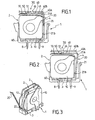
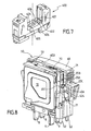
- the protection device is formed by a protection cell 1 which may comprise one or more modules 2 each containing a varistor 10 ( Figures 1, 2 and 3 ).
- Each module 2 advantageously comprises a base 3 made of electrically insulating material, a varistor 10, two electrically conductive electrodes 4 constituting the poles of the varistor 10 as well as disconnecting means 20.
- each module 2 is adapted to be electrically connected to a base 400 ( figure 7 ) by means of connection pads 8, 9 intended to be introduced into orifices 405, 406 provided on the base 400.
- connection pad 8 one of the poles of the varistor 10 is connected directly to a connection pad 8, the other pole of the varistor being connected to an electrode 4, which is welded to the connection means 20 which are in permanent electrical contact with each other. the other connection pad 9.
- the disconnecting means 20 are preferably formed by a thermal disconnector, such as for example a disconnection blade 21 in thermal and electrical contact with the associated varistor 10, so that the heating of the varistor, linked to the end of life of the latter, causes the opening of the disconnection blade 21, thus isolating the varistor lines to protect.
- a thermal disconnector such as for example a disconnection blade 21 in thermal and electrical contact with the associated varistor 10, so that the heating of the varistor, linked to the end of life of the latter, causes the opening of the disconnection blade 21, thus isolating the varistor lines to protect.
- the disconnection means 20 are thus able to move between a so-called closing position, in which the varistor 10 is connected to the network or electrical installation and an open position, in which the varistor 10 is disconnected from the electrical installation. These two positions are illustrated on the Figures 1 and 2 .
- the disconnection blade 21 extends between two ends 21A, 21B, one of the ends 21A being preferably fixed by means of a hot-melt welding on one of the electrodes 4.
- the end 21 A of the disconnection blade 21 is thus preferably welded in stress, so that when the varistor 10 reaches the end of its life, it becomes heated and causes the fusion or rupture of the weld which, once broken, allows the release of the disconnection blade 21.
- the display means 30 are adapted to inform a third party of the state of the varistors or varistors contained in the protection cell 1. These display means 30 are functionally connected to the disconnection means 20, that is to say that there are intermediate means for connecting the position of the disconnection means 20 to the indication provided by the display means 30.
- the display means 30 comprise, for each protection cell 1, a control part 40, distinct from the disconnection means 20 and able to move under the control of the latter.
- This control part 40 advantageously provides the connection between the disconnection means 20 and the display means 30.
- the display means 30 also comprise means 50 for indicating the state of the varistor 10 associated with the control part 40, so that the indication means 50 indicate, as a function of the position of the piece of command 40, if the varistor 10 is in use or disconnected.
- control part 40 and the disconnection means 20 are arranged relatively such that when opening the disconnection means 20, the latter release the control part 40 thus allowing the free movement, that is to say not controlled by the disconnection means 20, the latter.
- control part 40 is thus free to move, that is to say that it is neither actuated nor guided in displacement by the disconnection means 20.
- the disconnecting means 20 are, in their closed position, mounted so as to form a stop against the control part 40.
- the control part 40 advantageously comprises a bearing zone 40A which, when the disconnecting means 20 are in their closed position, bears against them ( figure 1 ).
- control part 40 and the disconnection means 20 are arranged such that when the disconnecting means 20 are in their closed position ( figure 1 ), the control part 40 is elastically constrained and comes into abutment, in particular through the bearing zone 40A, against the disconnection means 20, and thus exerts on them a driving constraint tending to push them towards their position opening.
- Such an arrangement therefore makes it possible to anticipate and secure the disconnection of the protection component. It also makes it possible to use a disconnection blade 21 having a moderate spring effect and thus to reduce the risk of mechanical embrittlement of the thermal disconnect welding.
- the design of the protection device and in particular the mounting of the display means 30 of the state of the varistor allows thus, thanks to the small number of parts cooperating together and the limited number of contact points between these parts to ensure a fast and reliable disconnection of the protection component. This reliability is further accentuated by the fact that the display means 30 are districts of the disconnection means 20.
- control part 40 is formed by a slider 41, made of electrically insulating material, able to move in a substantially rectilinear direction F.
- the front portion 41A of the slider 41 is specifically designed to bear against the disconnecting means 20, on the one hand when they are in their closed position and on the other hand, when opening the latter , so that the slider 41 is permanently in contact with the disconnecting means 20.
- the display means 30 are advantageously formed by mechanical means mounted in a housing 60, which also contains the varistor 10.
- the display means 30 also comprise a resilient means 70, spring-like, adapted to exert a restoring force on the control part 40 responsible for the displacement of the latter.
- the elastic means 70 is preferably interposed between firstly the control member 40, against which it bears elastically and secondly a fixed stop, for example formed by one of the inner walls of the housing 60.
- the elastic means 70 is thus advantageously adapted to occupy a compressed position when the control part 40 is constrained longitudinally, that is to say in a direction substantially parallel to the direction of displacement F and a rest position, when the workpiece control 40 is released from the disconnecting means 20 ( figure 2 ).
- the elastic means 70 thus constitutes a means of pre-stressing the control part 40.
- the slider 41 extends longitudinally in the direction F, and is preferably sufficiently rigid so that its front portion 41 A can come into firm support against the disconnection means 20 and more particularly against the end 21 A of the blade of disconnection 21.
- the end 21A of the disconnection blade 21 moves in the direction F and therefore no longer constitutes an obstacle or an abutment against of the control part 40.
- the resilient means 70 initially compressed, then tends to relax ( figure 2 ) thus causing the cursor 41 to move in the direction F.
- the slider 41 still bearing against the end 21 A of the disconnection blade 21, tends to force the latter towards its open position, participating thus actively disconnecting the protection component.
- the restoring force exerted by the elastic means 70 on the end 21 A of the disconnection blade 21 will preferably be greater than the resistance opposed by the blade of disconnection 21, to constrain the latter to move further away from the electrode 4.
- the indication means 50 is advantageously formed by a display member, preferably by a panel 51, for example rectangular, preferably disposed on the slider 41.
- the panel 51 may be formed by a piece of material insulating plastic, for example glued on the slider 41, but may also be simply formed by a colored strip painted on the slider 41.
- the panel 51 is also advantageously arranged to move at the same time as the control part 40 facing a window 61 formed in one of the faces 60B of the housing 60 located opposite the base 3, to obtain a different visual appearance through the window 61, depending on the position of the control part 40 .
- the elastic means 70 is compressed and the panel 51 is in a position offset from the window 61 and can not, in this configuration, be viewed from the outside. It then visualizes, looking through the window 61, the cursor 41 which may have, for example, a green color appearance, indicating to third parties that the varistor is in use.
- the panel 51 is in the field of the window 61. It is then likely to be viewed from the outside and preferably has a colored appearance, for example red, indicating to third parties that the varistor is disconnected.
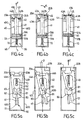
- the device comprises a protection cell 1 comprising a first and a second varistor 10 connected in parallel and respectively associated with a first and a second disconnecting means 20A, 20B.
- the display means 30 are preferably operatively connected to the first and second disconnecting means 20A, 20B so as to provide a differentiated indication of the state of each varistor 10 taken individually ( Figures 4a, 4b, 4c ).
- the indication means 50 is preferably formed by a display member, preferably a panel 51 mounted on or integral with the slider 41 and preferably disposed towards the end opposite to the front part 41 A so as to move opposite the viewing window 61.
- the panel 51 is preferably divided into two zones 51A, 51B arranged such that when the disconnecting means 20A, 20B are in the closed position ( figure 4a ), the area 51 A preferably green colored is substantially opposite the viewing window 61. In this way, the window appears green, indicating that the protection components are in use. On the contrary, when the two disconnecting means 20A, 20B are in the open position ( figure 4c ), it is the other area 51 B, preferably colored red, which is next to the window 61. In this configuration, the window 61 appears red indicating that the two varistors are disconnected.
- the window 61 is simultaneously occupied by at least a portion of each of the two areas 51A, 51B so that a portion, for example half of its surface appears red, the other part or half appearing green.
- the visual appearance of the window 61 thus indicates to third parties that only one varistor is disconnected.
- the amplitude of displacement of the slider 41 is thus adjusted so as to generate a different visual appearance through the window 61 as a function of the configuration of the disconnection means 20A, 20B.
- the slider 41 is elastically constrained by an elastic means 70 forcing it to bear, via its front portion 41A, against the disconnecting means 20A, 20B ( figure 4a ).
- control part 40 specifically the slider 41, comprises two bearing zone stages 42, 43 arranged one behind the other in the direction of movement F of the control part 40 so as to ensure the blocking of the latter successively in the two initial and intermediate positions.
- the structure of the control part 40 thus makes it possible to generate a stepwise displacement of the latter between the different initial, intermediate and final positions.
- control part 40 comprises a pair of so-called downstream support zones 42A, 42B intended to abut in the initial position ( figure 4a ), against the two means of disconnection 20A, 20B.
- the control part 40 also comprises a pair of so-called upstream bearing zones 43A, 43B disposed upstream of the first pair of downstream support zones 42A, 42B facing the direction of movement F of the control part 40, so that in the intermediate position ( figure 4b ), one of the upstream bearing areas 43A abuts against the corresponding disconnecting means 20A in the closed position.
- the display means 30 advantageously have a symmetry with respect to the plane S delimiting the separation between the two varistors.
- the upstream support zones 43A, 43B are preferably formed by fingers 44 protruding from each other and other of the control part 40 and extending in a direction substantially perpendicular to the main direction F of displacement of the control part 40.
- the device comprises guiding means in displacement of the control part 40, adapted to allow an angular displacement of the latter so as to allow, when opening one of the disconnecting means 20A, 20B, crossing the other disconnecting means 20A, 20B by the corresponding downstream support zone 42A, 42B.
- the displacement guiding means may advantageously be formed by the side walls 60C, 60D of the housing 60.
- the slider 41 is then advantageously disposed within the housing 60 so as to maintain a sufficient clearance between the contours of the slider 41 and the walls 60C , 60D to allow angular deflection.
- the cursor 41 must cross one of the disconnection means 20A remained in the closed position, and must for this purpose operate a slight rotation of an angle ⁇ allowing it to be released from the disconnection means 20A.
- the slider 41 can then continue its course until the upstream support zone 43A abuts against the disconnection means 20A.
- the disengagement means 45 are preferably formed by oblique cutouts, arranged on both sides. other of the slider 41, at its front portion 41A, said cutouts thus forming the downstream bearing areas 42A, 42B.
- the resilient means 70 also makes it possible to anticipate and secure the disconnection of the varistors by ensuring that the front end 41 A of the slider 41 is placed in abutment against the disconnection means 20A, 20B.
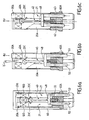
- the display means 30 advantageously comprise guide means 80 adapted to ensure the displacement of the control part 40 along a predetermined path formed by the combination of a rotational movement and a movement of rotation. translation.
- the control part 40 is elastically constrained by means of the elastic means 70 interposed between, on the one hand, the control part 40 and, on the other hand, a stop 62 mounted in a fixed manner within the housing 60.
- control part 40 Under the action of the resilient means 70, spring-like, the control member 40 bears against the disconnecting means 20A, 20B.
- the control part 40 comprises two end portions 46A, 46B, for example in the form of projecting studs, adapted to bear against each of the disconnection means 20A, 20B when they are in the closed position ( figure 5a ).
- the guiding means 80 of the control part 40 are advantageously formed by a lug 81, preferably arranged on the control part 40, and a corresponding groove 82, preferably V-shaped, in which the lug 81 is likely to move when the control part 40 passes successively in the different initial, intermediate and final positions illustrated on the Figures 5a, 5b and 5c .
- control part 40 In the initial position illustrated on the figure 5a , the control part 40 is in stable equilibrium and interposed between the elastic means 70 on the one hand and the disconnection means 20A, 20B on the other hand.
- one of the disconnection means 20B comes into the open position, it releases at least partially the control part 40 which is then able to move in rotation at an angle ⁇ until it comes into contact with one of the walls 60D of the housing 60, as illustrated on the figure 5b .
- control part 40 In this intermediate position, the control part 40 is also in a stable position and always bears elastically against the other disconnecting means 20A, through its end portion 46A.
- the displacement of the control part 40 between the initial position ( figure 5a ) and the intermediate position ( figure 5b ) follows a predetermined path, directly related to the path of the lug 81 in the groove 82.
- the indication means 50 is preferably formed by a display member, such as a display panel 51 preferably disposed at one end of the control piece 40 so as to move in view of the window 61 formed in the housing 60.
- a display member such as a display panel 51 preferably disposed at one end of the control piece 40 so as to move in view of the window 61 formed in the housing 60.
- the display panel 51 preferably colored green, is located substantially opposite the window 61 thus indicating that all the varistors are connected.
- the control part 40 is angularly offset from its initial position, so that the display panel 51 is also offset relative to the window 61.
- the latter then has a different visual appearance, indicating that one of the varistances is offline.
- part of the viewing window 61 may remain hidden by the control part 40, thus indicating to third parties that only a part of the protection components is disconnected.
- control part 40 When the other 20A disconnection means in turn turn in the open position, the control part 40, under the action of the elastic means 70, tends to move in a substantially straight direction F which has the effect of clearing completely the viewing window 61 which then has a homogeneous visual appearance, for example red, indicating that all the protective components are disconnected and need to be replaced.
- Such an arrangement has the advantage of not hinder disconnection in case of blocking of the display means 30.
- Another advantage of this arrangement is that it also makes it possible to participate in the disconnection via the elastic means 70 which, by exerting a thrust on the control part 40, promotes the displacement of the disconnection means 20A, 20B at the moment. fusion of the weld.
- Another advantage of this arrangement is that it is insensitive to vibrations or shocks that may occur for example during transport operations, the control part 40 always being able to return to its initial position under the effect of force. restoring force exerted by the elastic means 70.
- the indicating means 50 is formed by a remote indicator (not shown) operatively connected to the control part 40 via a remote signaling system.
- the indication means 50 may thus be formed by a visual, auditory or any other type of sensory indicator.
- the indication means 50 is not mechanically connected to the control part 40, but is deported, that is to say that it is connected to the latter by means of other means than mechanical means, in particular by remote signaling.
- the indicator is not located in the direct vicinity of the housing 60 but at a non-negligible distance from the latter.
- This variant embodiment of the device is represented in the case of two varistors connected in parallel, but can of course be applied to devices having only one varistor.
- the control part 40 is secured to two pins 52, 53 intended to engage in corresponding housings 401, 402 formed in a base 400 ( figure 7 ) intended to receive the protection cell 1.
- the pins 52, 53 are intended to cooperate with a mechanism disposed within the base 400, capable of triggering a minimum of interrupter, and thus signal the changes of state of the device to third parties located at distance from the housing 60.
- the mechanism and the associated remote signaling system provide a remote signal indicating that the two varistors of the device are connected.
- control part 40 is secured to the pins 52, 53 so that its displacement at the same time causes a substantially identical movement of the pins 52, 53 within passages 62, 63 formed in the lower wall 60A of the housing 60.
- control part 40 may be formed by a slider, and is preferably in the form of an elongated rod provided with a disk-shaped or sphere-shaped front portion 40A intended to bear against a fold 20C formed in the disconnecting means 20A, 20B, and designed to form a stop against the control part 40.
- the disconnecting means 20A, 20B When they are opened, the disconnecting means 20A, 20B release the control part 40, thus allowing the free movement of the latter. On the contrary, when the disconnecting means 20A, 20B are in the closed positions ( figure 6a ), the control member 40 is constrained between firstly the elastic means 70, tending to repel in the direction F, and secondly the disconnecting means 20A, 20B, precisely the folds 20C formed therein.
- the folds 20C preferably extend in a plane substantially perpendicular to the plane of extension of the disconnection blades 21. Even more preferably, the folds 20C may extend obliquely with respect to the blades of the disconnections 21, so that the front portion 40A of the control member 40 exerts on them a driving stress tending to push the disconnection blades 21 to their open position.
- control part 40 and the associated elastic means 70 then constitute means of assisting the disconnection of the protective components of the device.
- the control part 40 is sufficiently flexible to allow angular movement of its front portion 40A. Indeed, as it is represented on the Figures 6a, 6b and 6c , creases. 20C provided in the disconnecting means 20A, 20b protrude so as to form stops against the front portion 40A of the control member 40. Therefore, when one of the disconnection means 20A goes into position d opening, the control part 40, precisely the front portion 40A of the latter must be released from the protruding portion of the fold 20C of the disconnection means 20B remained in the closed position, so as to cross the latter.
- control member 40 The lateral flexibility of the control member 40 then allows sufficient angular movement of its front portion 40A so that the latter can cross, under the action of the elastic means 70, the stop formed by the fold 20C.
- control part 40 has a section narrowing 48, giving it its flexible character.
- the control part 40 is advantageously elastically constrained between the elastic means 70 on the one hand, and the disconnecting means 20A, 20B, precisely the stops formed by the folds 20C on the other hand.
- the control part 40 Upon opening of one of the disconnecting means 20A, 20B, for example the disconnecting means 20A, the control part 40 is released, and driven in displacement under the action of the elastic means 70.
- the control part 40 is then likely to move in the main direction F with a small angular offset ⁇ so as to disengage the disconnecting means 20B remained in the closed position and whose fold 20C protrudes against the front portion 40A of the control room 40. Once this obstacle is passed, the control part 40 is free to move towards its final position illustrated on the Figure 6c .
- control part 40 simultaneously drives the pins 52, 53 out of their housings 401, 402 within the base 400, thus triggering the control of a new signal at distance indicating that at least one of the varistors of the device is disconnected.
- the device comprises several display means, namely direct viewing means and remote viewing means.
- the device comprises a first control part 403, associated with a direct display member of the display panel type 51, and a second control part 404, associated with a remote indicator (not shown), the first and second control pieces 403, 404 being adapted to cooperate independently of one another with the disconnecting means 20A, 20B.
- the assembly associating the first control part 403 with the direct display member may be of the type shown in FIGS. Figures 1, 2 , 4a, 4b, 4c, 5a, 5b, 5c .
- the assembly combining the second control part 404 with a remote indicator it may be of the type shown on the Figures 6a, 6b, 6c .
- the opening of the disconnection means 20A, 20B almost simultaneously causes the release of the first and second control pieces 403, 404, thus indicating that at least one varistor is disconnected, and this on the one hand through the display panel 51 and on the other hand via the remote indicator.
- Such a device thus makes it possible to associate within the same housing 60, two separate control pieces 403, 404, and capable of actuating two additional indication means of the state of the protection components, namely a means proximity indication, for example in the form of a display panel 51, and a remote indication means, which is advantageously in the form of a remote indicator, for example visual or sound.
- the protection device according to the invention thus makes it possible, thanks to a particularly simple mounting of the display means 30, to ensure not only a reliable and efficient disconnection of the varistors when the latter are in a degraded state, but also to enable simultaneously to a third to visualize the state of these varistors, and this by limiting the risk of seizure of the mechanism or possible problems of guiding parts.
- the invention finds its application in electrical devices for protection against transient overvoltages.
Landscapes
- Engineering & Computer Science (AREA)
- Microelectronics & Electronic Packaging (AREA)
- Physics & Mathematics (AREA)
- Electromagnetism (AREA)
- Fuses (AREA)
- Emergency Protection Circuit Devices (AREA)
- Details Of Connecting Devices For Male And Female Coupling (AREA)
- Thermistors And Varistors (AREA)
Claims (21)
- Vorrichtung zum Schutz einer elektrischen Anlage vor Überspannungen, die Folgendes umfasst:- zwei Schutzbauteile (10), die parallel geschaltet sind und einem ersten beziehungsweise einem zweien Trennungsmittel (20, 20A, 20B) des jeweiligen Schutzbauteils (10) zugehörig sind, die angepasst sind, um dieses letztere von der elektrischen Anlage zu trennen und sich zwischen einer geschlossenen Stellung, in der das entsprechende Schutzbauteil (10) verbunden ist, und einer geöffneten Stellung zu verschieben, in der das entsprechende Schutzbauteil (10) getrennt ist,- Mittel zur Anzeige (30) des Zustands der Schutzbauteile (10), die funktionell an die Trennungsmittel (20, 20A, 20B) angeschlossen sind und Folgendes umfassen:- Mindestens ein Steuerteil (40), das sich von den Trennungsmitteln (20, 20A, 20B) unterscheidet und in der Lage ist, sich in Abhängigkeit von diesen letzteren zu verschieben,- mindestens ein Mittel zur Angabe (50) des Zustands der Schutzbauteile (10), das dem Steuerteil (40) zugehörig ist, derart, dass das Angabemittel (50) entsprechend der Stellung des Steuerteils (40) angibt, ob die Schutzbauteile (10) in Betrieb oder getrennt sind,wobei die Anzeigemittel (30) funktionell an das erste und das zweite Trennungsmittel (20A, 20B) angeschlossen sind, um eine differenzierte Anzeige des Zustands von jedem der Schutzbauteile (10) einzeln zu liefern,
dadurch gekennzeichnet, dass das Steuerteil (40) und die Trennungsmittel (20, 20A, 20B) derart in Bezug aufeinander angeordnet sind, dass bei der Öffnung der Trennungsmittel (20, 20A, 20B) diese letzteren das Steuerteil (40) freigeben und so die Verschiebung dieses letzteren zulassen, und
wobei das Steuerteil (40) zwischen Folgendem federnd beweglich gelagert ist:- einer Ausgangsstellung, die einem verbundenen Zustand der zwei Schutzbauteile (10) entspricht, in der das Steuerteil (40) durch die zwei Trennungsmittel (20A, 20B) in seiner Stellung gehalten wird,- einer Zwischenstellung, die in Bezug auf die Ausgangsstellung versetzt ist und die einem Zustand entspricht, in dem ein einziges der Trennungsmittel (20A, 20B) getrennt ist, in der das Steuerteil (40) durch das Trennungsmittel (20A, 20B) in der geschlossenen Stellung gehalten wird, und- einer Endstellung, die in Bezug auf die Zwischenstellung versetzt ist und einem getrennten Zustand der zwei Trennungsmittel (20A, 20B) entspricht. - Vorrichtung nach Anspruch 1, dadurch gekennzeichnet, dass die Trennungsmittel (20, 20A, 20B) in ihrer geschlossenen Stellung derart gelagert sind, dass sie dem Steuerteil (40) gegenüber einen Anschlag bilden.
- Vorrichtung nach Anspruch 1 oder 2, dadurch gekennzeichnet, dass das Steuerteil (40) und die Trennungsmittel (20, 20A, 20B) derart angeordnet sind, dass das Steuerteil (40), wenn die Trennungsmittel (20, 20A, 20B) sich in ihrer geschlossenen Stellung befinden, federnd gespannt ist und gegen die Trennungsmittel (20, 20A, 20B) in Anlage kommt, wodurch es auf diese letzteren eine antreibende Spannung ausübt, die dazu neigt, sie in Richtung ihrer geöffneten Stellung zurückzudrücken.
- Vorrichtung nach einem der Ansprüche 1 bis 3, dadurch gekennzeichnet, dass das Steuerteil (40) durch einen Schieber (41) gebildet ist, der in der Lage ist, sich in eine im Wesentlichen geradlinige Richtung (F) zu verschieben und dessen Stirnabschnitt (41A) dafür gedacht ist, um gegen die Trennungsmittel (20, 20A, 20B) in Anlage zu kommen.
- Vorrichtung nach Anspruch 3 oder 4, dadurch gekennzeichnet, dass die Anzeigemittel (30) ein federndes Mittel (70) umfassen, das angepasst ist, um eine Rückstellkraft auf das Steuerteil (40) auszuüben, die für die Verschiebung dieses letzteren verantwortlich ist.
- Vorrichtung nach einem der vorhergehenden Ansprüche, dadurch gekennzeichnet, dass das Steuerteil (40) zwei Stufen von Anlagebereichen (42, 42) umfasst, die derart nacheinander in der Verschiebungsrichtung (F) des Steuerteils (40) angeordnet sind, dass die Sperrung des Steuerteils (40) nacheinander in den zwei Ausgangs- und Zwischenstellungen gewährleistet ist.
- Vorrichtung nach Anspruch 6, dadurch gekennzeichnet, dass das Steuerteil ein Paar sogenannte nachgelagerte Anlagebereiche (42A, 42B), die dazu bestimmt sind, in der Ausgangsstellung gegen die zwei Trennungsmittel (20A, 20B) in Anschlag zu kommen, und ein Paar sogenannte vorgelagerte Anlagebereiche (43A, 43B) umfasst, die hinsichtlich der Verschiebungsrichtung des Steuerteils dem ersten Paar vorgelagert angeordnet sind, derart, dass der eine der vorgelagerten Anlagebereiche (43A, 43B) in der Zwischenstellung gegen das entsprechende, in der geschlossenen Stellung gebliebene Trennungsmittel (20A, 20B) in Anschlag kommt.
- Vorrichtung nach Anspruch 7, dadurch gekennzeichnet, dass die vorgelagerten Anlagebereiche (43A, 43B) durch Zapfen (44) gebildet sind, die auf beiden Seiten des Steuerteils (40) hervorstehen und sich in einer Richtung erstrecken, die im Wesentlichen senkrecht zur Hauptverschiebungsrichtung des Steuerteils (40) ist.
- Vorrichtung nach Anspruch 7 oder 8, dadurch gekennzeichnet, dass sie Mittel zur Führung der Verschiebung des Steuerteils (40) umfasst, die angepasst sind, um einen ausreichenden WinckelnausschlagAusschlag dieses letzteren zuzulassen, um bei der Öffnung des einen der Trennungsmittel (20A, 20B) die Überwindung des anderen Trennungsmittels durch den einen der entsprechenden nachgelagerten Anlagebereiche (42A, 42B) zu erlauben.
- Vorrichtung nach Anspruch 9, dadurch gekennzeichnet, dass das Steuerteil (40) mit Auslösungsmitteln (45) versehen ist, die gestaltet sind, um beim Übergang des Steuerteils (40) von der Anfangsstellung in Richtung der Zwischenstellung die Überwindung des in der geschlossenen Stellung gebliebenen Trennungsmittels (20A, 20B) zu erleichtern.
- Vorrichtung nach Anspruch 10, dadurch gekennzeichnet, dass die Auslösungsmittel (45) durch schräge Ausschnitte gebildet sind, die auf beiden Seiten des Steuerteils (40) am Ende dieses letzteren eingerichtet sind und die nachgelagerten Anlagebereiche (42A, 42B) bilden.
- Vorrichtung nach einem der vorhergehenden Ansprüche, dadurch gekennzeichnet, dass sie Führungsmittel (80) umfasst, die angepasst sind, um die Verschiebung des Steuerteils (40) gemäß einem vorbestimmten Weg zu gewährleistet, der durch die Kombination einer Drehbewegung und einer Translationsbewegung gebildet ist.
- Vorrichtung nach Anspruch 12, dadurch gekennzeichnet, dass die Führungsmittel (80) durch einen Stift (81), der auf dem Steuerteil (40) angeordnet ist, und einer entsprechenden V-förmigen Nut (82) gebildet sind, in der der Stift (81) sich verschieben kann.
- Vorrichtung nach einem der vorhergehenden Ansprüche, dadurch gekennzeichnet, dass das Angabemittel (50) durch mindestens ein Anzeigeorgan, vorzugsweise eine Anzeigetafel (51), gebildet ist, das dem Steuerteil zugehörig ist, derart, dass es sich gegenüber einem Fenster (61), das im Gehäuse (60) der Vorrichtung eingerichtet ist, verschiebt, um entsprechend der Stellung des Steuerteils (40) ein unterschiedliches Aussehen durch das Fenster (61) zu erhalten.
- Vorrichtung nach einem der Ansprüche 1 bis 5, dadurch gekennzeichnet, dass das Angabemittel (50) durch einen verschobenen Anzeiger gebildet ist, der mittels eines Fernsignalisierungssystems funktionell an das Steuerteil (40) angeschlossen ist.
- Vorrichtung nach Anspruch 15, dadurch gekennzeichnet, dass das Steuerteil (40) ausreichend biegsam ist, um einen Ausschlag Winckelnausschlag seines Stirnabschnitts (40A) zuzulassen.
- Vorrichtung nach Anspruch 16, dadurch gekennzeichnet, dass das Steuerteil (40) eine Querschnittsverengung umfasst, die ihm eine biegsame Eigenschaft verleiht.
- Vorrichtung nach einem der Ansprüche 15 bis 17, dadurch gekennzeichnet, dass der Stirnabschnitt (40A) des Steuerteils (40) die Form einer Kugel aufweist, die dazu bestimmt ist, gegen eine Krümmung (20C) in Anlage zu kommen, die in den Trennungsmitteln (20A, 20B) eingerichtet ist, wobei die Krümmung (20C) zum Bilden eines Anschlags gegenüber dem Steuerteil (40) gedacht ist.
- Vorrichtung nach einem der vorhergehenden Ansprüche, dadurch gekennzeichnet, dass das Schutzbauteil (10) durch einen Varistor gebildet ist.
- Vorrichtung nach einem der vorhergehenden Ansprüche, dadurch gekennzeichnet, dass jedes Trennungsmittel (20A, 20B) durch ein Trennungsblatt (21) gebildet ist, das an den einen der Pole des entsprechenden Schutzbauteils (10) geschweißt ist und in der Lage ist, sich nach dem Schmelzen der Schweißung unter der Wirkung einer federnden Rückstellkraft von der geschlossenen Stellung in Richtung der offenen Stellung zu verschieben und so das Steuerteil (40) freizugeben.
- Vorrichtung nach einem der vorhergehenden Ansprüche, dadurch gekennzeichnet, dass sie ein erstes Steuerteil (403), das einem Direktanzeigeorgan zugehörig ist, sowie ein zweites Steuerteil (404) umfasst, das einem verschobenen Hinweisanzeiger zugehörig ist, wobei das erste und das zweie Steuerteil (403, 404) angepasst sind, um unabhängig voneinander mit den Trennungsmitteln (20A, 20B, 20C) zusammenzuwirken.
Applications Claiming Priority (1)
| Application Number | Priority Date | Filing Date | Title |
|---|---|---|---|
| PCT/FR2004/000960 WO2005112211A1 (fr) | 2004-04-19 | 2004-04-19 | Dispositif de protection contre les surtensions pourvu de moyens de deconnexion et de visualisation ameliores |
Publications (2)
| Publication Number | Publication Date |
|---|---|
| EP1745533A1 EP1745533A1 (de) | 2007-01-24 |
| EP1745533B1 true EP1745533B1 (de) | 2012-06-06 |
Family
ID=34958053
Family Applications (1)
| Application Number | Title | Priority Date | Filing Date |
|---|---|---|---|
| EP04742540A Expired - Lifetime EP1745533B1 (de) | 2004-04-19 | 2004-04-19 | Überspannungsschutzeinrichtung mit verbesserten trenn- und visuellen anzeigemitteln |
Country Status (8)
| Country | Link |
|---|---|
| US (1) | US7684166B2 (de) |
| EP (1) | EP1745533B1 (de) |
| CN (1) | CN100566056C (de) |
| BR (1) | BRPI0418761A (de) |
| CA (1) | CA2563552A1 (de) |
| ES (1) | ES2386546T3 (de) |
| MX (1) | MXPA06012057A (de) |
| WO (1) | WO2005112211A1 (de) |
Families Citing this family (42)
| Publication number | Priority date | Publication date | Assignee | Title |
|---|---|---|---|---|
| FR2897989B1 (fr) | 2006-02-24 | 2008-05-09 | Soule Prot Surtensions Sa | Dispositif de protection contre les surtensions avec systeme de visualisation simplifie et procede de fabrication correspondant |
| DE102007030653B4 (de) * | 2007-07-02 | 2017-04-13 | Phoenix Contact Gmbh & Co. Kg | Überspannungsschutzelement |
| DE102008048644B4 (de) * | 2008-08-01 | 2017-08-24 | DEHN + SÖHNE GmbH + Co. KG. | Überspannungsschutzgerät mit einem oder mehreren parallel geschalteten, in einer baulichen Einheit befindlichen überspannungsbegrenzenden Elementen |
| DE102009022069B4 (de) * | 2009-01-12 | 2016-10-20 | Dehn + Söhne Gmbh + Co. Kg | Überspannungsableiter |
| DE102009036125A1 (de) * | 2009-08-05 | 2011-02-10 | Phoenix Contact Gmbh & Co. Kg | Überspannungsschutzelement |
| DE102009053145A1 (de) * | 2009-11-05 | 2011-05-12 | Phoenix Contact Gmbh & Co. Kg | Überspannungsschutzelement |
| DE102010010980A1 (de) * | 2010-03-10 | 2011-09-15 | Phoenix Contact Gmbh & Co. Kg | Überspannungsschutzelement |
| FR2958789B1 (fr) * | 2010-04-09 | 2012-05-11 | Abb France | Dispositif de protection contre les surtensions transitoires a deconnecteur thermique ameliore |
| DE102010015814B4 (de) * | 2010-04-20 | 2014-08-07 | Phoenix Contact Gmbh & Co. Kg | Überspannungsschutzelement |
| US9147510B2 (en) | 2010-04-20 | 2015-09-29 | Phoenix Contact Gmbh & Co. Kg | Overvoltage protection element |
| CN101887790B (zh) * | 2010-06-13 | 2012-07-04 | 深圳科安达电子科技股份有限公司 | 防雷用压敏电阻 |
| CN102377176A (zh) * | 2010-08-13 | 2012-03-14 | 施耐德电器工业公司 | 浪涌保护设备 |
| DE102011018556A1 (de) * | 2011-02-18 | 2012-08-23 | Dehn + Söhne Gmbh + Co. Kg | Überspannungsschutzeinrichtung, umfassend mindestens einen Überspannungsableiter |
| CZ304868B6 (cs) * | 2011-04-01 | 2014-12-17 | Saltek S.R.O. | Svodič přepětí s výměnným modulem přepěťové ochrany |
| EP2541579B1 (de) * | 2011-06-30 | 2015-11-04 | Epcos Ag | Elektrisches Gerät |
| CN103094013B (zh) * | 2011-11-07 | 2015-12-23 | 施耐德电器工业公司 | 电涌保护器的脱扣机构和电涌保护器 |
| US8743525B2 (en) | 2012-06-19 | 2014-06-03 | Raycap Intellectual Property, Ltd | Overvoltage protection devices including wafer of varistor material |
| DE102013006052B4 (de) * | 2013-02-08 | 2016-08-04 | DEHN + SÖHNE GmbH + Co. KG. | Überspannungsschutzgerät |
| DE102013022348B4 (de) * | 2013-10-22 | 2016-01-07 | Dehn + Söhne Gmbh + Co. Kg | Überspannungsschutzeinrichtung, aufweisend mindestens einen Überspannungsableiter und eine, mit dem Überspannungsableiter in Reihe geschaltete, thermisch auslösbare Schalteinrichtung |
| US20170110279A1 (en) * | 2014-04-07 | 2017-04-20 | Littelfuse, Inc. | Thermal metal oxide varistor circuit protection device |
| US9906017B2 (en) | 2014-06-03 | 2018-02-27 | Ripd Research And Ip Development Ltd. | Modular overvoltage protection units |
| TWM514689U (zh) * | 2015-08-28 | 2015-12-21 | 蘇州市台基防雷科技有限公司 | 側彈式突波吸收模組 |
| US10319545B2 (en) | 2016-11-30 | 2019-06-11 | Iskra Za{hacek over (s)}{hacek over (c)}ite d.o.o. | Surge protective device modules and DIN rail device systems including same |
| US10707678B2 (en) | 2016-12-23 | 2020-07-07 | Ripd Research And Ip Development Ltd. | Overvoltage protection device including multiple varistor wafers |
| US10447026B2 (en) | 2016-12-23 | 2019-10-15 | Ripd Ip Development Ltd | Devices for active overvoltage protection |
| US10340110B2 (en) * | 2017-05-12 | 2019-07-02 | Raycap IP Development Ltd | Surge protective device modules including integral thermal disconnect mechanisms and methods including same |
| US10388479B2 (en) * | 2017-06-27 | 2019-08-20 | Shanghai Chenzhu Instrument Co., Ltd. | Surge protector, and release mechanism and base thereof |
| US10685767B2 (en) | 2017-09-14 | 2020-06-16 | Raycap IP Development Ltd | Surge protective device modules and systems including same |
| KR101985499B1 (ko) * | 2017-12-28 | 2019-06-03 | 삼화콘덴서공업 주식회사 | 과전류 보호 기능을 가지는 금속 산화물 바리스터 |
| TWI848960B (zh) | 2018-07-23 | 2024-07-21 | 加拿大商Ifd科技股份有限公司 | 溫度感測器及指示器 |
| US11223200B2 (en) | 2018-07-26 | 2022-01-11 | Ripd Ip Development Ltd | Surge protective devices, circuits, modules and systems including same |
| DE102020107318B4 (de) * | 2020-03-17 | 2023-06-22 | Dehn Se | Überspannungsschutzvorrichtung sowie modulares Überspannungsschutzsystem |
| CN214588697U (zh) * | 2021-04-16 | 2021-11-02 | 厦门赛尔特电子有限公司 | 一种具有双脱扣机构的电涌保护器 |
| US11862967B2 (en) | 2021-09-13 | 2024-01-02 | Raycap, S.A. | Surge protective device assembly modules |
| US11723145B2 (en) | 2021-09-20 | 2023-08-08 | Raycap IP Development Ltd | PCB-mountable surge protective device modules and SPD circuit systems and methods including same |
| US11990745B2 (en) | 2022-01-12 | 2024-05-21 | Raycap IP Development Ltd | Methods and systems for remote monitoring of surge protective devices |
| US12506334B2 (en) | 2022-01-24 | 2025-12-23 | Raycap IP Development Ltd | Surge protective device modules and assemblies |
| US12199412B2 (en) | 2022-06-02 | 2025-01-14 | Ripd Ip Development Ltd. | Surge protective devices, circuits, modules and systems including same |
| CN115359981B (zh) * | 2022-09-06 | 2024-05-24 | 福建省乔光电子科技有限公司 | 一种热保护压敏电阻器模块 |
| US12206234B2 (en) | 2022-09-20 | 2025-01-21 | Ripd Ip Development Ltd | Overvoltage protection device modules |
| US12437906B2 (en) | 2022-10-18 | 2025-10-07 | Raycap, S.A. | Surge protective devices |
| US12580381B2 (en) | 2023-12-04 | 2026-03-17 | Ripd Ip Development Ltd | Overvoltage protection device modules and sheath bonding systems including same |
Family Cites Families (5)
| Publication number | Priority date | Publication date | Assignee | Title |
|---|---|---|---|---|
| FR2696588B1 (fr) | 1992-10-07 | 1994-12-09 | Legrand Sa | Limiteur de surtension à moyen indicateur de mise en défaut. |
| DE4437122C2 (de) * | 1994-10-01 | 1996-07-18 | Krone Ag | Überspannungsschutzstecker |
| FR2761543B1 (fr) * | 1997-03-25 | 1999-06-04 | Citel | Dispositif de protection d'un circuit electrique basse tension, module pour un tel dispositif de protection, et circuit pour le module |
| US6430019B1 (en) * | 1998-06-08 | 2002-08-06 | Ferraz S.A. | Circuit protection device |
| FR2783365B1 (fr) * | 1998-09-15 | 2000-12-01 | Soule Materiel Electr | Dispositif de protection d'installations electriques contre les perturbations de l'alimentation |
-
2004
- 2004-04-19 ES ES04742540T patent/ES2386546T3/es not_active Expired - Lifetime
- 2004-04-19 CN CNB200480023550XA patent/CN100566056C/zh not_active Expired - Fee Related
- 2004-04-19 US US11/568,090 patent/US7684166B2/en not_active Expired - Fee Related
- 2004-04-19 WO PCT/FR2004/000960 patent/WO2005112211A1/fr not_active Ceased
- 2004-04-19 CA CA002563552A patent/CA2563552A1/en not_active Abandoned
- 2004-04-19 BR BRPI0418761-0A patent/BRPI0418761A/pt not_active IP Right Cessation
- 2004-04-19 EP EP04742540A patent/EP1745533B1/de not_active Expired - Lifetime
- 2004-04-19 MX MXPA06012057A patent/MXPA06012057A/es not_active Application Discontinuation
Also Published As
| Publication number | Publication date |
|---|---|
| US7684166B2 (en) | 2010-03-23 |
| WO2005112211A1 (fr) | 2005-11-24 |
| CN1784814A (zh) | 2006-06-07 |
| BRPI0418761A (pt) | 2007-10-09 |
| EP1745533A1 (de) | 2007-01-24 |
| MXPA06012057A (es) | 2007-01-25 |
| ES2386546T3 (es) | 2012-08-22 |
| US20080043395A1 (en) | 2008-02-21 |
| CA2563552A1 (en) | 2005-11-24 |
| CN100566056C (zh) | 2009-12-02 |
Similar Documents
| Publication | Publication Date | Title |
|---|---|---|
| EP1745533B1 (de) | Überspannungsschutzeinrichtung mit verbesserten trenn- und visuellen anzeigemitteln | |
| EP1826795B1 (de) | Vorrichtung zum Schutz gegen Überspannungen mit vereinfachtem Anzeigesystem und entsprechendes Herstellungsverfahren | |
| EP0716493B1 (de) | Schutzvorrichtung gegen transiente Überspannungen mit Varistoren und thermischen Auslösern | |
| EP1743346B1 (de) | Überspannungsschutzeinrichtung mit lichtbogenlöschelementen | |
| EP1826793B1 (de) | Vorrichtung zum Schutz gegen Überspannungen mit Thermoschalter mit doppelter Kontaktfläche | |
| EP3319194B1 (de) | Schutzvorrichtung gegen vorübergehende überspannungen | |
| FR2783365A1 (fr) | Dispositif de protection d'installations electriques contre les perturbations de l'alimentation | |
| EP2375426A1 (de) | Varistor, der eine Elektrode mit einem vorstehenden Teil umfasst, der einen Kontakt bildet und Blitzableiter, der einen solchen Varistor umfasst | |
| WO2004064213A1 (fr) | Dispositif de protection contre des surtensions | |
| FR2914108A1 (fr) | Fusible thermique pour boitier electronique et procede d'implantation d'un tel fusible dans un boitier electronique | |
| EP2958126B1 (de) | Abschaltanzeige einer aktiven komponente einer schutzvorrichtung einer elektrischen anlage | |
| EP1747564B1 (de) | Überspannungs-schutzeinrichtung mit einem verbesserten display-system | |
| EP0845843B1 (de) | Schutzvorrichtung für Telephonlinien | |
| FR2625377A1 (fr) | Parafoudre de surete | |
| EP1708221B1 (de) | Mit einer Schmelzsicherung und einem aus Isoliermaterial hergestellten Ausschaltelement versehene Schutzvorichtung, und ihre Anwedung bei Überspannungsableitern | |
| EP1820200A1 (de) | Einrichtung zum schutz einer elektrischen installation, entsprechendes verfahren und verwendung | |
| FR3094147A1 (fr) | Dispositif de protection contre les surtensions | |
| EP1698029B1 (de) | Überspannungsschutzvorrichtung mit klemmanordnung | |
| EP1708222B1 (de) | Mit einem pressverbunden und in der Ausschaltrichtung vorgespannten Schmelzelement versehene Schutzvorichtung, und ihre Anwedung bei Überspannungsableitern | |
| WO2007065997A1 (fr) | Dispositif de protection contre les surtensions a securite amelioree et procede de fabrication correspondant | |
| FR2723642A1 (fr) | Dispositif pour detecter et exploiter un courant de foudre circulant sur une ligne electrique | |
| BE630625A (de) | ||
| FR2783362A1 (fr) | Ensemble de gestion de reseaux electriques comportant des moyens de connexion perfectionnes | |
| FR3022681A1 (fr) | Agencement d'un dispositif de protection d'une installation electrique | |
| FR2885458A1 (fr) | Dispositif de protection et circuit et installation d'alimentation electrique en comportant application |
Legal Events
| Date | Code | Title | Description |
|---|---|---|---|
| PUAI | Public reference made under article 153(3) epc to a published international application that has entered the european phase |
Free format text: ORIGINAL CODE: 0009012 |
|
| 17P | Request for examination filed |
Effective date: 20061117 |
|
| AK | Designated contracting states |
Kind code of ref document: A1 Designated state(s): AT BE BG CH CY CZ DE DK EE ES FI FR GB GR HU IE IT LI LU MC NL PL PT RO SE SI SK TR |
|
| DAX | Request for extension of the european patent (deleted) | ||
| RAP1 | Party data changed (applicant data changed or rights of an application transferred) |
Owner name: ABB FRANCE |
|
| 17Q | First examination report despatched |
Effective date: 20101011 |
|
| GRAP | Despatch of communication of intention to grant a patent |
Free format text: ORIGINAL CODE: EPIDOSNIGR1 |
|
| GRAC | Information related to communication of intention to grant a patent modified |
Free format text: ORIGINAL CODE: EPIDOSCIGR1 |
|
| GRAS | Grant fee paid |
Free format text: ORIGINAL CODE: EPIDOSNIGR3 |
|
| GRAA | (expected) grant |
Free format text: ORIGINAL CODE: 0009210 |
|
| RAP1 | Party data changed (applicant data changed or rights of an application transferred) |
Owner name: ABB FRANCE |
|
| AK | Designated contracting states |
Kind code of ref document: B1 Designated state(s): AT BE BG CH CY CZ DE DK EE ES FI FR GB GR HU IE IT LI LU MC NL PL PT RO SE SI SK TR |
|
| REG | Reference to a national code |
Ref country code: GB Ref legal event code: FG4D Free format text: NOT ENGLISH |
|
| REG | Reference to a national code |
Ref country code: AT Ref legal event code: REF Ref document number: 561421 Country of ref document: AT Kind code of ref document: T Effective date: 20120615 Ref country code: CH Ref legal event code: EP |
|
| REG | Reference to a national code |
Ref country code: IE Ref legal event code: FG4D Free format text: LANGUAGE OF EP DOCUMENT: FRENCH |
|
| REG | Reference to a national code |
Ref country code: DE Ref legal event code: R096 Ref document number: 602004038071 Country of ref document: DE Effective date: 20120802 |
|
| REG | Reference to a national code |
Ref country code: ES Ref legal event code: FG2A Ref document number: 2386546 Country of ref document: ES Kind code of ref document: T3 Effective date: 20120822 |
|
| REG | Reference to a national code |
Ref country code: NL Ref legal event code: VDEP Effective date: 20120606 |
|
| PG25 | Lapsed in a contracting state [announced via postgrant information from national office to epo] |
Ref country code: SE Free format text: LAPSE BECAUSE OF FAILURE TO SUBMIT A TRANSLATION OF THE DESCRIPTION OR TO PAY THE FEE WITHIN THE PRESCRIBED TIME-LIMIT Effective date: 20120606 Ref country code: CY Free format text: LAPSE BECAUSE OF FAILURE TO SUBMIT A TRANSLATION OF THE DESCRIPTION OR TO PAY THE FEE WITHIN THE PRESCRIBED TIME-LIMIT Effective date: 20120606 Ref country code: FI Free format text: LAPSE BECAUSE OF FAILURE TO SUBMIT A TRANSLATION OF THE DESCRIPTION OR TO PAY THE FEE WITHIN THE PRESCRIBED TIME-LIMIT Effective date: 20120606 |
|
| REG | Reference to a national code |
Ref country code: AT Ref legal event code: MK05 Ref document number: 561421 Country of ref document: AT Kind code of ref document: T Effective date: 20120606 |
|
| PG25 | Lapsed in a contracting state [announced via postgrant information from national office to epo] |
Ref country code: GR Free format text: LAPSE BECAUSE OF FAILURE TO SUBMIT A TRANSLATION OF THE DESCRIPTION OR TO PAY THE FEE WITHIN THE PRESCRIBED TIME-LIMIT Effective date: 20120907 Ref country code: SI Free format text: LAPSE BECAUSE OF FAILURE TO SUBMIT A TRANSLATION OF THE DESCRIPTION OR TO PAY THE FEE WITHIN THE PRESCRIBED TIME-LIMIT Effective date: 20120606 |
|
| PG25 | Lapsed in a contracting state [announced via postgrant information from national office to epo] |
Ref country code: CZ Free format text: LAPSE BECAUSE OF FAILURE TO SUBMIT A TRANSLATION OF THE DESCRIPTION OR TO PAY THE FEE WITHIN THE PRESCRIBED TIME-LIMIT Effective date: 20120606 Ref country code: RO Free format text: LAPSE BECAUSE OF FAILURE TO SUBMIT A TRANSLATION OF THE DESCRIPTION OR TO PAY THE FEE WITHIN THE PRESCRIBED TIME-LIMIT Effective date: 20120606 Ref country code: EE Free format text: LAPSE BECAUSE OF FAILURE TO SUBMIT A TRANSLATION OF THE DESCRIPTION OR TO PAY THE FEE WITHIN THE PRESCRIBED TIME-LIMIT Effective date: 20120606 Ref country code: AT Free format text: LAPSE BECAUSE OF FAILURE TO SUBMIT A TRANSLATION OF THE DESCRIPTION OR TO PAY THE FEE WITHIN THE PRESCRIBED TIME-LIMIT Effective date: 20120606 Ref country code: NL Free format text: LAPSE BECAUSE OF FAILURE TO SUBMIT A TRANSLATION OF THE DESCRIPTION OR TO PAY THE FEE WITHIN THE PRESCRIBED TIME-LIMIT Effective date: 20120606 Ref country code: SK Free format text: LAPSE BECAUSE OF FAILURE TO SUBMIT A TRANSLATION OF THE DESCRIPTION OR TO PAY THE FEE WITHIN THE PRESCRIBED TIME-LIMIT Effective date: 20120606 |
|
| PG25 | Lapsed in a contracting state [announced via postgrant information from national office to epo] |
Ref country code: PL Free format text: LAPSE BECAUSE OF FAILURE TO SUBMIT A TRANSLATION OF THE DESCRIPTION OR TO PAY THE FEE WITHIN THE PRESCRIBED TIME-LIMIT Effective date: 20120606 Ref country code: PT Free format text: LAPSE BECAUSE OF FAILURE TO SUBMIT A TRANSLATION OF THE DESCRIPTION OR TO PAY THE FEE WITHIN THE PRESCRIBED TIME-LIMIT Effective date: 20121008 |
|
| PLBE | No opposition filed within time limit |
Free format text: ORIGINAL CODE: 0009261 |
|
| STAA | Information on the status of an ep patent application or granted ep patent |
Free format text: STATUS: NO OPPOSITION FILED WITHIN TIME LIMIT |
|
| PG25 | Lapsed in a contracting state [announced via postgrant information from national office to epo] |
Ref country code: DK Free format text: LAPSE BECAUSE OF FAILURE TO SUBMIT A TRANSLATION OF THE DESCRIPTION OR TO PAY THE FEE WITHIN THE PRESCRIBED TIME-LIMIT Effective date: 20120606 |
|
| 26N | No opposition filed |
Effective date: 20130307 |
|
| REG | Reference to a national code |
Ref country code: DE Ref legal event code: R097 Ref document number: 602004038071 Country of ref document: DE Effective date: 20130307 |
|
| PG25 | Lapsed in a contracting state [announced via postgrant information from national office to epo] |
Ref country code: BG Free format text: LAPSE BECAUSE OF FAILURE TO SUBMIT A TRANSLATION OF THE DESCRIPTION OR TO PAY THE FEE WITHIN THE PRESCRIBED TIME-LIMIT Effective date: 20120906 |
|
| BERE | Be: lapsed |
Owner name: ABB FRANCE Effective date: 20130430 |
|
| PG25 | Lapsed in a contracting state [announced via postgrant information from national office to epo] |
Ref country code: MC Free format text: LAPSE BECAUSE OF FAILURE TO SUBMIT A TRANSLATION OF THE DESCRIPTION OR TO PAY THE FEE WITHIN THE PRESCRIBED TIME-LIMIT Effective date: 20120606 |
|
| REG | Reference to a national code |
Ref country code: CH Ref legal event code: PL |
|
| REG | Reference to a national code |
Ref country code: IE Ref legal event code: MM4A |
|
| PG25 | Lapsed in a contracting state [announced via postgrant information from national office to epo] |
Ref country code: LI Free format text: LAPSE BECAUSE OF NON-PAYMENT OF DUE FEES Effective date: 20130430 Ref country code: CH Free format text: LAPSE BECAUSE OF NON-PAYMENT OF DUE FEES Effective date: 20130430 Ref country code: BE Free format text: LAPSE BECAUSE OF NON-PAYMENT OF DUE FEES Effective date: 20130430 |
|
| PG25 | Lapsed in a contracting state [announced via postgrant information from national office to epo] |
Ref country code: IE Free format text: LAPSE BECAUSE OF NON-PAYMENT OF DUE FEES Effective date: 20130419 |
|
| PGFP | Annual fee paid to national office [announced via postgrant information from national office to epo] |
Ref country code: GB Payment date: 20140422 Year of fee payment: 11 |
|
| PGFP | Annual fee paid to national office [announced via postgrant information from national office to epo] |
Ref country code: ES Payment date: 20140428 Year of fee payment: 11 Ref country code: DE Payment date: 20140418 Year of fee payment: 11 Ref country code: IT Payment date: 20140428 Year of fee payment: 11 Ref country code: FR Payment date: 20140422 Year of fee payment: 11 |
|
| PG25 | Lapsed in a contracting state [announced via postgrant information from national office to epo] |
Ref country code: TR Free format text: LAPSE BECAUSE OF FAILURE TO SUBMIT A TRANSLATION OF THE DESCRIPTION OR TO PAY THE FEE WITHIN THE PRESCRIBED TIME-LIMIT Effective date: 20120606 |
|
| PG25 | Lapsed in a contracting state [announced via postgrant information from national office to epo] |
Ref country code: LU Free format text: LAPSE BECAUSE OF NON-PAYMENT OF DUE FEES Effective date: 20130419 Ref country code: HU Free format text: LAPSE BECAUSE OF FAILURE TO SUBMIT A TRANSLATION OF THE DESCRIPTION OR TO PAY THE FEE WITHIN THE PRESCRIBED TIME-LIMIT; INVALID AB INITIO Effective date: 20040419 |
|
| REG | Reference to a national code |
Ref country code: DE Ref legal event code: R119 Ref document number: 602004038071 Country of ref document: DE |
|
| GBPC | Gb: european patent ceased through non-payment of renewal fee |
Effective date: 20150419 |
|
| PG25 | Lapsed in a contracting state [announced via postgrant information from national office to epo] |
Ref country code: DE Free format text: LAPSE BECAUSE OF NON-PAYMENT OF DUE FEES Effective date: 20151103 Ref country code: GB Free format text: LAPSE BECAUSE OF NON-PAYMENT OF DUE FEES Effective date: 20150419 Ref country code: IT Free format text: LAPSE BECAUSE OF NON-PAYMENT OF DUE FEES Effective date: 20150419 |
|
| REG | Reference to a national code |
Ref country code: FR Ref legal event code: ST Effective date: 20151231 |
|
| PG25 | Lapsed in a contracting state [announced via postgrant information from national office to epo] |
Ref country code: FR Free format text: LAPSE BECAUSE OF NON-PAYMENT OF DUE FEES Effective date: 20150430 |
|
| REG | Reference to a national code |
Ref country code: ES Ref legal event code: FD2A Effective date: 20160804 |
|
| PG25 | Lapsed in a contracting state [announced via postgrant information from national office to epo] |
Ref country code: ES Free format text: LAPSE BECAUSE OF NON-PAYMENT OF DUE FEES Effective date: 20150420 |