EP1745533B1 - Surge voltage protection device with improved disconnection and visual indication means - Google Patents
Surge voltage protection device with improved disconnection and visual indication means Download PDFInfo
- Publication number
- EP1745533B1 EP1745533B1 EP04742540A EP04742540A EP1745533B1 EP 1745533 B1 EP1745533 B1 EP 1745533B1 EP 04742540 A EP04742540 A EP 04742540A EP 04742540 A EP04742540 A EP 04742540A EP 1745533 B1 EP1745533 B1 EP 1745533B1
- Authority
- EP
- European Patent Office
- Prior art keywords
- control part
- disconnector
- disconnection
- protection
- varistor
- Prior art date
- Legal status (The legal status is an assumption and is not a legal conclusion. Google has not performed a legal analysis and makes no representation as to the accuracy of the status listed.)
- Expired - Lifetime
Links
Images
Classifications
-
- H—ELECTRICITY
- H01—ELECTRIC ELEMENTS
- H01C—RESISTORS
- H01C7/00—Non-adjustable resistors formed as one or more layers or coatings; Non-adjustable resistors made from powdered conducting material or powdered semi-conducting material with or without insulating material
- H01C7/10—Non-adjustable resistors formed as one or more layers or coatings; Non-adjustable resistors made from powdered conducting material or powdered semi-conducting material with or without insulating material voltage responsive, i.e. varistors
- H01C7/12—Overvoltage protection resistors; Arresters
- H01C7/126—Means for protecting against excessive pressure or for disconnecting in case of failure
-
- H—ELECTRICITY
- H01—ELECTRIC ELEMENTS
- H01T—SPARK GAPS; OVERVOLTAGE ARRESTERS USING SPARK GAPS; SPARKING PLUGS; CORONA DEVICES; GENERATING IONS TO BE INTRODUCED INTO NON-ENCLOSED GASES
- H01T1/00—Details of spark gaps
- H01T1/12—Means structurally associated with spark gap for recording operation thereof
Definitions
- the present invention relates to the general technical field of protective devices for installations and equipment, electrical against transient electrical surges.
- Protection devices for electrical installations are commonly used to protect electrical or electronic devices against overvoltages that can be, for example, generated by discharges due to lightning.
- These devices generally comprise an active part formed by one or more protection components, such as for example a varistor or a spark gap.
- protection components such as for example a varistor or a spark gap.
- Varistors are commonly used components to protect electrical installations or equipment against transient overvoltages.
- the varistor When an overvoltage occurs within the installation, the varistor experiences a current shock which has the effect of degrading it and causing it to overheat, making its thermal disconnection necessary.
- the degradation of the varistor is difficult, if not impossible to predict, since it depends not only on the number of current shocks experienced by the varistor during its lifetime, but also on their amplitude.
- each varistor In order to allow rapid identification of a defective varistor and to reduce the above-mentioned latency, it is known to equip each varistor with display means that can indicate to a third party that the varistor is out of service.
- the varistors generally encountered are thus associated with disconnection means adapted to disconnect the varistor when it is in a degraded state and before it heats up too much, to which are connected functionally the display means of the device.
- state of the varistor generally actuated by the means of disconnection, and which make it possible to indicate to a third party whether the varistor is in use or disconnected.
- the display means may thus be in the form of a cursor associated with a viewing piece and able to move in translation under the action of the disconnection means, so as to indicate, according to its position, the state of the varistor and this, by means of the facing of the viewing part, for example a colored screen, with a viewing window formed in the housing of the protective device.
- the cursor and the viewing piece are either secured to the disconnection means, in particular a disconnection blade, or independent while being controlled and actuated by the latter.
- the cursor or the viewing part is obstructed (e) in its movement, especially in the case where the cursor and / or the viewing part are improperly sized or if the guide means are defective, leading thus to a bad guidance of the cursor.
- the cursor and / or the viewing piece can then hinder or even prevent the disconnection of the varistor.
- the latter then remains connected and the display means indicate no anomaly while the varistor is greatly degraded, and may cause a fire due to its heating.
- the assemblies in which the cursor, and / or the viewing piece are actuated and their displacement controlled by the disconnection means generally require perfecting the dimensioning of the pieces, so as firstly to avoid the formation of games between these, and on the other hand to avoid any risk of blocking the disconnection system and / or visualization.
- the disconnection blades are generally designed so as to have a large spring effect, capable of compensating for the braking effect exerted possibly by the cursor and / or the viewing room.
- the objects assigned to the invention therefore aim to remedy the various disadvantages listed above and to propose a new device for protecting electrical installations against overvoltages which ensures a particularly reliable and rapid disconnection of the protection component.
- Another object of the invention is to propose a new device for protecting electrical installations against overvoltages which is capable of indicating in a simple, reliable and instantaneous manner the state of the protection component.
- a voltage cutter device for cutting off surges in an electrical circuit.
- This device comprises a metal oxide varistor.
- the temperature of the varistor increases when the voltage applied to its terminals exceeds a predetermined value.
- a pair of electrical contact elements is provided for electrically connecting the varistor to a power line of an electrical circuit, on the one hand, and to the ground or the neutral line of the electrical circuit, on the other hand.
- One of these contact elements is in the form of an arm portion of a contact element fixed to the varistor by means of a low temperature solder.
- the varistor heats up to the temperature at which the low temperature solder melts.
- the arm portion breaks off the varistor - thus disconnecting the varistor from the rest of the circuit - and can deviate from the varistor.
- this arm portion when the arm portion is attached to the varistor, this arm portion maintains a shield in a first position, wherein the shield is not interposed between the arm portion and the varistor.
- the protective screen interposes between the arm portion and the varistor.
- the protective screen thus makes it possible to indicate a heating of the varistor.
- EP-A-0 987 803 discloses a device for protecting an electrical installation against overvoltages comprising two varistors. Each varistor is associated with a cursor. Each cursor can be moved in translation between a closed position, in which the associated component is connected, and an open position, in which the associated component is disconnected. The slider is held in its closed position by a weld. A spring tends to move the cursor to its open position.
- the device according to EP-A-0 987 803 also includes display means operatively connected to the cursor. These display means comprise a moving part adapted to move according to the cursor. The display means also includes indicator means in the form of an extension adapted to move relative to the orifice to indicate whether the varistor is connected or disconnected.
- Another object of the invention is to provide a new device for protecting electrical installations against overvoltages whose design is particularly simple and economical.
- Another object of the invention is to propose a new device for protecting electrical installations against overvoltages requiring only a limited number of parts to obtain the connection / disconnection function on the one hand, and the visualization function on the other hand. go.
- Another object of the invention is to propose a new device for protecting electrical installations against overvoltages enabling simultaneous and differentiated visualization of the state of several protection components connected in parallel.
- Another object of the invention is to propose a new device for protecting electrical installations against overvoltages making it possible to provide a remote indication of the state of the protection component.
- the overvoltage protection device according to the invention is intended to be branched into the equipment or the installation electric to protect.
- the term " electrical installation" refers to any type of device or network that is susceptible to voltage disturbances, including transient overvoltages due to lightning. In the latter case, it is formed by a surge arrester.
- the overvoltage protection device according to the invention is advantageously intended to be disposed between a phase of the installation to be protected and the earth.
- the device instead of being connected bypass between a phase and the earth, is connected between the neutral and the earth, between the phase and the neutral, or between two phases (case of differential protection).
- the protection device comprises at least one protection component 10 forming the active part, for example a surge arrester, intended to protect the electrical installation.
- each protection component 10 present in the device is formed by a varistor, it being understood that the use of a varistor is only indicated by way of example and does not constitute in no way a limitation of the invention.
- the protection device comprises two varistors 10, means 20 of disconnection of each varistor, sensitive to their degree of aging and adapted to individually disconnect each varistor of the electrical installation when the varistors are in a degraded state .
- the protection device according to the invention also comprises means 30 for visualizing the state of each varistor 10, functionally connected to the disconnection means 20.
- the protection device is formed by a protection cell 1 which may comprise one or more modules 2 each containing a varistor 10 ( Figures 1, 2 and 3 ).
- Each module 2 advantageously comprises a base 3 made of electrically insulating material, a varistor 10, two electrically conductive electrodes 4 constituting the poles of the varistor 10 as well as disconnecting means 20.
- each module 2 is adapted to be electrically connected to a base 400 ( figure 7 ) by means of connection pads 8, 9 intended to be introduced into orifices 405, 406 provided on the base 400.
- connection pad 8 one of the poles of the varistor 10 is connected directly to a connection pad 8, the other pole of the varistor being connected to an electrode 4, which is welded to the connection means 20 which are in permanent electrical contact with each other. the other connection pad 9.
- the disconnecting means 20 are preferably formed by a thermal disconnector, such as for example a disconnection blade 21 in thermal and electrical contact with the associated varistor 10, so that the heating of the varistor, linked to the end of life of the latter, causes the opening of the disconnection blade 21, thus isolating the varistor lines to protect.
- a thermal disconnector such as for example a disconnection blade 21 in thermal and electrical contact with the associated varistor 10, so that the heating of the varistor, linked to the end of life of the latter, causes the opening of the disconnection blade 21, thus isolating the varistor lines to protect.
- the disconnection means 20 are thus able to move between a so-called closing position, in which the varistor 10 is connected to the network or electrical installation and an open position, in which the varistor 10 is disconnected from the electrical installation. These two positions are illustrated on the Figures 1 and 2 .
- the disconnection blade 21 extends between two ends 21A, 21B, one of the ends 21A being preferably fixed by means of a hot-melt welding on one of the electrodes 4.
- the end 21 A of the disconnection blade 21 is thus preferably welded in stress, so that when the varistor 10 reaches the end of its life, it becomes heated and causes the fusion or rupture of the weld which, once broken, allows the release of the disconnection blade 21.
- the display means 30 are adapted to inform a third party of the state of the varistors or varistors contained in the protection cell 1. These display means 30 are functionally connected to the disconnection means 20, that is to say that there are intermediate means for connecting the position of the disconnection means 20 to the indication provided by the display means 30.
- the display means 30 comprise, for each protection cell 1, a control part 40, distinct from the disconnection means 20 and able to move under the control of the latter.
- This control part 40 advantageously provides the connection between the disconnection means 20 and the display means 30.
- the display means 30 also comprise means 50 for indicating the state of the varistor 10 associated with the control part 40, so that the indication means 50 indicate, as a function of the position of the piece of command 40, if the varistor 10 is in use or disconnected.
- control part 40 and the disconnection means 20 are arranged relatively such that when opening the disconnection means 20, the latter release the control part 40 thus allowing the free movement, that is to say not controlled by the disconnection means 20, the latter.
- control part 40 is thus free to move, that is to say that it is neither actuated nor guided in displacement by the disconnection means 20.
- the disconnecting means 20 are, in their closed position, mounted so as to form a stop against the control part 40.
- the control part 40 advantageously comprises a bearing zone 40A which, when the disconnecting means 20 are in their closed position, bears against them ( figure 1 ).
- control part 40 and the disconnection means 20 are arranged such that when the disconnecting means 20 are in their closed position ( figure 1 ), the control part 40 is elastically constrained and comes into abutment, in particular through the bearing zone 40A, against the disconnection means 20, and thus exerts on them a driving constraint tending to push them towards their position opening.
- Such an arrangement therefore makes it possible to anticipate and secure the disconnection of the protection component. It also makes it possible to use a disconnection blade 21 having a moderate spring effect and thus to reduce the risk of mechanical embrittlement of the thermal disconnect welding.
- the design of the protection device and in particular the mounting of the display means 30 of the state of the varistor allows thus, thanks to the small number of parts cooperating together and the limited number of contact points between these parts to ensure a fast and reliable disconnection of the protection component. This reliability is further accentuated by the fact that the display means 30 are districts of the disconnection means 20.
- control part 40 is formed by a slider 41, made of electrically insulating material, able to move in a substantially rectilinear direction F.
- the front portion 41A of the slider 41 is specifically designed to bear against the disconnecting means 20, on the one hand when they are in their closed position and on the other hand, when opening the latter , so that the slider 41 is permanently in contact with the disconnecting means 20.
- the display means 30 are advantageously formed by mechanical means mounted in a housing 60, which also contains the varistor 10.
- the display means 30 also comprise a resilient means 70, spring-like, adapted to exert a restoring force on the control part 40 responsible for the displacement of the latter.
- the elastic means 70 is preferably interposed between firstly the control member 40, against which it bears elastically and secondly a fixed stop, for example formed by one of the inner walls of the housing 60.
- the elastic means 70 is thus advantageously adapted to occupy a compressed position when the control part 40 is constrained longitudinally, that is to say in a direction substantially parallel to the direction of displacement F and a rest position, when the workpiece control 40 is released from the disconnecting means 20 ( figure 2 ).
- the elastic means 70 thus constitutes a means of pre-stressing the control part 40.
- the slider 41 extends longitudinally in the direction F, and is preferably sufficiently rigid so that its front portion 41 A can come into firm support against the disconnection means 20 and more particularly against the end 21 A of the blade of disconnection 21.
- the end 21A of the disconnection blade 21 moves in the direction F and therefore no longer constitutes an obstacle or an abutment against of the control part 40.
- the resilient means 70 initially compressed, then tends to relax ( figure 2 ) thus causing the cursor 41 to move in the direction F.
- the slider 41 still bearing against the end 21 A of the disconnection blade 21, tends to force the latter towards its open position, participating thus actively disconnecting the protection component.
- the restoring force exerted by the elastic means 70 on the end 21 A of the disconnection blade 21 will preferably be greater than the resistance opposed by the blade of disconnection 21, to constrain the latter to move further away from the electrode 4.
- the indication means 50 is advantageously formed by a display member, preferably by a panel 51, for example rectangular, preferably disposed on the slider 41.
- the panel 51 may be formed by a piece of material insulating plastic, for example glued on the slider 41, but may also be simply formed by a colored strip painted on the slider 41.
- the panel 51 is also advantageously arranged to move at the same time as the control part 40 facing a window 61 formed in one of the faces 60B of the housing 60 located opposite the base 3, to obtain a different visual appearance through the window 61, depending on the position of the control part 40 .
- the elastic means 70 is compressed and the panel 51 is in a position offset from the window 61 and can not, in this configuration, be viewed from the outside. It then visualizes, looking through the window 61, the cursor 41 which may have, for example, a green color appearance, indicating to third parties that the varistor is in use.
- the panel 51 is in the field of the window 61. It is then likely to be viewed from the outside and preferably has a colored appearance, for example red, indicating to third parties that the varistor is disconnected.
- the device comprises a protection cell 1 comprising a first and a second varistor 10 connected in parallel and respectively associated with a first and a second disconnecting means 20A, 20B.
- the display means 30 are preferably operatively connected to the first and second disconnecting means 20A, 20B so as to provide a differentiated indication of the state of each varistor 10 taken individually ( Figures 4a, 4b, 4c ).
- the indication means 50 is preferably formed by a display member, preferably a panel 51 mounted on or integral with the slider 41 and preferably disposed towards the end opposite to the front part 41 A so as to move opposite the viewing window 61.
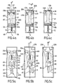
- the panel 51 is preferably divided into two zones 51A, 51B arranged such that when the disconnecting means 20A, 20B are in the closed position ( figure 4a ), the area 51 A preferably green colored is substantially opposite the viewing window 61. In this way, the window appears green, indicating that the protection components are in use. On the contrary, when the two disconnecting means 20A, 20B are in the open position ( figure 4c ), it is the other area 51 B, preferably colored red, which is next to the window 61. In this configuration, the window 61 appears red indicating that the two varistors are disconnected.
- the window 61 is simultaneously occupied by at least a portion of each of the two areas 51A, 51B so that a portion, for example half of its surface appears red, the other part or half appearing green.
- the visual appearance of the window 61 thus indicates to third parties that only one varistor is disconnected.
- the amplitude of displacement of the slider 41 is thus adjusted so as to generate a different visual appearance through the window 61 as a function of the configuration of the disconnection means 20A, 20B.
- the slider 41 is elastically constrained by an elastic means 70 forcing it to bear, via its front portion 41A, against the disconnecting means 20A, 20B ( figure 4a ).
- control part 40 specifically the slider 41, comprises two bearing zone stages 42, 43 arranged one behind the other in the direction of movement F of the control part 40 so as to ensure the blocking of the latter successively in the two initial and intermediate positions.
- the structure of the control part 40 thus makes it possible to generate a stepwise displacement of the latter between the different initial, intermediate and final positions.
- control part 40 comprises a pair of so-called downstream support zones 42A, 42B intended to abut in the initial position ( figure 4a ), against the two means of disconnection 20A, 20B.
- the control part 40 also comprises a pair of so-called upstream bearing zones 43A, 43B disposed upstream of the first pair of downstream support zones 42A, 42B facing the direction of movement F of the control part 40, so that in the intermediate position ( figure 4b ), one of the upstream bearing areas 43A abuts against the corresponding disconnecting means 20A in the closed position.
- the display means 30 advantageously have a symmetry with respect to the plane S delimiting the separation between the two varistors.
- the upstream support zones 43A, 43B are preferably formed by fingers 44 protruding from each other and other of the control part 40 and extending in a direction substantially perpendicular to the main direction F of displacement of the control part 40.
- the device comprises guiding means in displacement of the control part 40, adapted to allow an angular displacement of the latter so as to allow, when opening one of the disconnecting means 20A, 20B, crossing the other disconnecting means 20A, 20B by the corresponding downstream support zone 42A, 42B.
- the displacement guiding means may advantageously be formed by the side walls 60C, 60D of the housing 60.
- the slider 41 is then advantageously disposed within the housing 60 so as to maintain a sufficient clearance between the contours of the slider 41 and the walls 60C , 60D to allow angular deflection.
- the cursor 41 must cross one of the disconnection means 20A remained in the closed position, and must for this purpose operate a slight rotation of an angle ⁇ allowing it to be released from the disconnection means 20A.
- the slider 41 can then continue its course until the upstream support zone 43A abuts against the disconnection means 20A.
- the disengagement means 45 are preferably formed by oblique cutouts, arranged on both sides. other of the slider 41, at its front portion 41A, said cutouts thus forming the downstream bearing areas 42A, 42B.
- the resilient means 70 also makes it possible to anticipate and secure the disconnection of the varistors by ensuring that the front end 41 A of the slider 41 is placed in abutment against the disconnection means 20A, 20B.
- the display means 30 advantageously comprise guide means 80 adapted to ensure the displacement of the control part 40 along a predetermined path formed by the combination of a rotational movement and a movement of rotation. translation.
- the control part 40 is elastically constrained by means of the elastic means 70 interposed between, on the one hand, the control part 40 and, on the other hand, a stop 62 mounted in a fixed manner within the housing 60.
- control part 40 Under the action of the resilient means 70, spring-like, the control member 40 bears against the disconnecting means 20A, 20B.
- the control part 40 comprises two end portions 46A, 46B, for example in the form of projecting studs, adapted to bear against each of the disconnection means 20A, 20B when they are in the closed position ( figure 5a ).
- the guiding means 80 of the control part 40 are advantageously formed by a lug 81, preferably arranged on the control part 40, and a corresponding groove 82, preferably V-shaped, in which the lug 81 is likely to move when the control part 40 passes successively in the different initial, intermediate and final positions illustrated on the Figures 5a, 5b and 5c .
- control part 40 In the initial position illustrated on the figure 5a , the control part 40 is in stable equilibrium and interposed between the elastic means 70 on the one hand and the disconnection means 20A, 20B on the other hand.
- one of the disconnection means 20B comes into the open position, it releases at least partially the control part 40 which is then able to move in rotation at an angle ⁇ until it comes into contact with one of the walls 60D of the housing 60, as illustrated on the figure 5b .
- control part 40 In this intermediate position, the control part 40 is also in a stable position and always bears elastically against the other disconnecting means 20A, through its end portion 46A.
- the displacement of the control part 40 between the initial position ( figure 5a ) and the intermediate position ( figure 5b ) follows a predetermined path, directly related to the path of the lug 81 in the groove 82.
- the indication means 50 is preferably formed by a display member, such as a display panel 51 preferably disposed at one end of the control piece 40 so as to move in view of the window 61 formed in the housing 60.
- a display member such as a display panel 51 preferably disposed at one end of the control piece 40 so as to move in view of the window 61 formed in the housing 60.
- the display panel 51 preferably colored green, is located substantially opposite the window 61 thus indicating that all the varistors are connected.
- the control part 40 is angularly offset from its initial position, so that the display panel 51 is also offset relative to the window 61.
- the latter then has a different visual appearance, indicating that one of the varistances is offline.
- part of the viewing window 61 may remain hidden by the control part 40, thus indicating to third parties that only a part of the protection components is disconnected.
- control part 40 When the other 20A disconnection means in turn turn in the open position, the control part 40, under the action of the elastic means 70, tends to move in a substantially straight direction F which has the effect of clearing completely the viewing window 61 which then has a homogeneous visual appearance, for example red, indicating that all the protective components are disconnected and need to be replaced.
- Such an arrangement has the advantage of not hinder disconnection in case of blocking of the display means 30.
- Another advantage of this arrangement is that it also makes it possible to participate in the disconnection via the elastic means 70 which, by exerting a thrust on the control part 40, promotes the displacement of the disconnection means 20A, 20B at the moment. fusion of the weld.
- Another advantage of this arrangement is that it is insensitive to vibrations or shocks that may occur for example during transport operations, the control part 40 always being able to return to its initial position under the effect of force. restoring force exerted by the elastic means 70.
- the indicating means 50 is formed by a remote indicator (not shown) operatively connected to the control part 40 via a remote signaling system.
- the indication means 50 may thus be formed by a visual, auditory or any other type of sensory indicator.
- the indication means 50 is not mechanically connected to the control part 40, but is deported, that is to say that it is connected to the latter by means of other means than mechanical means, in particular by remote signaling.
- the indicator is not located in the direct vicinity of the housing 60 but at a non-negligible distance from the latter.
- This variant embodiment of the device is represented in the case of two varistors connected in parallel, but can of course be applied to devices having only one varistor.
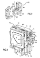
- the control part 40 is secured to two pins 52, 53 intended to engage in corresponding housings 401, 402 formed in a base 400 ( figure 7 ) intended to receive the protection cell 1.
- the pins 52, 53 are intended to cooperate with a mechanism disposed within the base 400, capable of triggering a minimum of interrupter, and thus signal the changes of state of the device to third parties located at distance from the housing 60.
- the mechanism and the associated remote signaling system provide a remote signal indicating that the two varistors of the device are connected.
- control part 40 is secured to the pins 52, 53 so that its displacement at the same time causes a substantially identical movement of the pins 52, 53 within passages 62, 63 formed in the lower wall 60A of the housing 60.
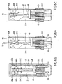
- control part 40 may be formed by a slider, and is preferably in the form of an elongated rod provided with a disk-shaped or sphere-shaped front portion 40A intended to bear against a fold 20C formed in the disconnecting means 20A, 20B, and designed to form a stop against the control part 40.
- the disconnecting means 20A, 20B When they are opened, the disconnecting means 20A, 20B release the control part 40, thus allowing the free movement of the latter. On the contrary, when the disconnecting means 20A, 20B are in the closed positions ( figure 6a ), the control member 40 is constrained between firstly the elastic means 70, tending to repel in the direction F, and secondly the disconnecting means 20A, 20B, precisely the folds 20C formed therein.
- the folds 20C preferably extend in a plane substantially perpendicular to the plane of extension of the disconnection blades 21. Even more preferably, the folds 20C may extend obliquely with respect to the blades of the disconnections 21, so that the front portion 40A of the control member 40 exerts on them a driving stress tending to push the disconnection blades 21 to their open position.
- control part 40 and the associated elastic means 70 then constitute means of assisting the disconnection of the protective components of the device.
- the control part 40 is sufficiently flexible to allow angular movement of its front portion 40A. Indeed, as it is represented on the Figures 6a, 6b and 6c , creases. 20C provided in the disconnecting means 20A, 20b protrude so as to form stops against the front portion 40A of the control member 40. Therefore, when one of the disconnection means 20A goes into position d opening, the control part 40, precisely the front portion 40A of the latter must be released from the protruding portion of the fold 20C of the disconnection means 20B remained in the closed position, so as to cross the latter.
- control member 40 The lateral flexibility of the control member 40 then allows sufficient angular movement of its front portion 40A so that the latter can cross, under the action of the elastic means 70, the stop formed by the fold 20C.
- control part 40 has a section narrowing 48, giving it its flexible character.
- the control part 40 is advantageously elastically constrained between the elastic means 70 on the one hand, and the disconnecting means 20A, 20B, precisely the stops formed by the folds 20C on the other hand.
- the control part 40 Upon opening of one of the disconnecting means 20A, 20B, for example the disconnecting means 20A, the control part 40 is released, and driven in displacement under the action of the elastic means 70.
- the control part 40 is then likely to move in the main direction F with a small angular offset ⁇ so as to disengage the disconnecting means 20B remained in the closed position and whose fold 20C protrudes against the front portion 40A of the control room 40. Once this obstacle is passed, the control part 40 is free to move towards its final position illustrated on the Figure 6c .
- control part 40 simultaneously drives the pins 52, 53 out of their housings 401, 402 within the base 400, thus triggering the control of a new signal at distance indicating that at least one of the varistors of the device is disconnected.
- the device comprises several display means, namely direct viewing means and remote viewing means.
- the device comprises a first control part 403, associated with a direct display member of the display panel type 51, and a second control part 404, associated with a remote indicator (not shown), the first and second control pieces 403, 404 being adapted to cooperate independently of one another with the disconnecting means 20A, 20B.
- the assembly associating the first control part 403 with the direct display member may be of the type shown in FIGS. Figures 1, 2 , 4a, 4b, 4c, 5a, 5b, 5c .
- the assembly combining the second control part 404 with a remote indicator it may be of the type shown on the Figures 6a, 6b, 6c .
- the opening of the disconnection means 20A, 20B almost simultaneously causes the release of the first and second control pieces 403, 404, thus indicating that at least one varistor is disconnected, and this on the one hand through the display panel 51 and on the other hand via the remote indicator.
- Such a device thus makes it possible to associate within the same housing 60, two separate control pieces 403, 404, and capable of actuating two additional indication means of the state of the protection components, namely a means proximity indication, for example in the form of a display panel 51, and a remote indication means, which is advantageously in the form of a remote indicator, for example visual or sound.
- the protection device according to the invention thus makes it possible, thanks to a particularly simple mounting of the display means 30, to ensure not only a reliable and efficient disconnection of the varistors when the latter are in a degraded state, but also to enable simultaneously to a third to visualize the state of these varistors, and this by limiting the risk of seizure of the mechanism or possible problems of guiding parts.
- the invention finds its application in electrical devices for protection against transient overvoltages.
Landscapes
- Engineering & Computer Science (AREA)
- Microelectronics & Electronic Packaging (AREA)
- Physics & Mathematics (AREA)
- Electromagnetism (AREA)
- Fuses (AREA)
- Emergency Protection Circuit Devices (AREA)
- Details Of Connecting Devices For Male And Female Coupling (AREA)
- Thermistors And Varistors (AREA)
Abstract
Description
La présente invention se rapporte au domaine technique général des dispositifs de protection d'installations et d'équipements, électriques contre des surtensions électriques transitoires.The present invention relates to the general technical field of protective devices for installations and equipment, electrical against transient electrical surges.
La présente invention concerne plus particulièrement un dispositif de protection d'une installation électrique contre les surtensions comportant :
- au moins un composant de protection,
- des moyens de déconnexion du composant de protection, adaptés pour déconnecter ce dernier de l'installation électrique, et susceptibles de se déplacer entre une position de fermeture, dans laquelle le composant de protection est connecté, et une position d'ouverture, dans laquelle le composant de protection est déconnecté,
- des moyens de visualisation de l'état du composant de protection, reliés fonctionnellement aux moyens de déconnexion et comportant :
- au moins une pièce de commande, distincte des moyens de déconnexion et apte à se déplacer sous la dépendance de ces derniers,
- au moins un moyen d'indication de l'état du composant de protection, associé à la pièce de commande de telle manière que le moyen d'indication indique, en fonction de la position de la pièce de commande, si le composant de protection est en service ou déconnecté.
- at least one protection component,
- means for disconnecting the protection component, adapted to disconnect the latter from the electrical installation, and capable of moving between a closed position, in which the protection component is connected, and an open position, in which the protection component is disconnected,
- means for displaying the state of the protection component, functionally connected to the disconnection means and comprising:
- at least one control part, distinct from the disconnection means and able to move under the control of the latter,
- at least one means for indicating the state of the protection component, associated with the control part so that the indicating means indicates, as a function of the position of the control part, if the protection component is in use or disconnected.
Les dispositifs de protection d'installations électriques sont couramment utilisés pour protéger notamment des appareils électriques ou électroniques contre les surtensions pouvant être, par exemple, générées par des décharges dues à la foudre.Protection devices for electrical installations are commonly used to protect electrical or electronic devices against overvoltages that can be, for example, generated by discharges due to lightning.
Ces dispositifs comportent de manière générale une partie active formée par un ou plusieurs composants de protection, tels que par exemple une varistance ou un éclateur.These devices generally comprise an active part formed by one or more protection components, such as for example a varistor or a spark gap.
Les varistances sont des composants couramment utilisés pour protéger des installations ou des équipements électriques contre les surtensions transitoires.Varistors are commonly used components to protect electrical installations or equipment against transient overvoltages.
Lorsqu'une surtension se produit au sein de l'installation, la varistance subit un choc de courant qui a pour effet de la dégrader et de provoquer son échauffement, rendant nécessaire sa déconnexion thermique.When an overvoltage occurs within the installation, the varistor experiences a current shock which has the effect of degrading it and causing it to overheat, making its thermal disconnection necessary.
La dégradation de la varistance est difficile, voire impossible à prévoir, dans la mesure où elle dépend non seulement du nombre de chocs de courant subis par la varistance au cours de sa vie, mais également de leur amplitude.The degradation of the varistor is difficult, if not impossible to predict, since it depends not only on the number of current shocks experienced by the varistor during its lifetime, but also on their amplitude.
Il est par conséquent difficile de prévoir a priori la durée de vie et le degré de vieillissement d'une varistance et l'utilisateur est souvent amené à constater a posteriori la destruction de cette dernière, de telle sorte que l'installation court le risque de fonctionner pendant un certain temps de latence sans protection.It is therefore difficult to predict a priori the lifetime and the degree of aging of a varistor and the user is often led to note a posteriori the destruction of the latter, so that the installation runs the risk of running for some latency without protection.
Afin de permettre un repérage rapide d'une varistance défectueuse et de diminuer le temps de latence susmentionné, il est connu d'équiper chaque varistance avec des moyens de visualisation susceptibles d'indiquer à un tiers que la varistance est hors service.In order to allow rapid identification of a defective varistor and to reduce the above-mentioned latency, it is known to equip each varistor with display means that can indicate to a third party that the varistor is out of service.
Les varistances généralement rencontrées sont ainsi associées à des moyens de déconnexion adaptés pour déconnecter la varistance lorsqu'elle se trouve dans un état dégradé et avant qu'elle ne s'échauffe de manière trop importante, auxquels sont reliés fonctionnellement des moyens de visualisation de l'état de la varistance, généralement actionnés par les moyens de déconnexion, et qui permettent d'indiquer à un tiers si la varistance est en service ou déconnectée.The varistors generally encountered are thus associated with disconnection means adapted to disconnect the varistor when it is in a degraded state and before it heats up too much, to which are connected functionally the display means of the device. state of the varistor, generally actuated by the means of disconnection, and which make it possible to indicate to a third party whether the varistor is in use or disconnected.
Les moyens de visualisation peuvent ainsi se présenter sous la forme d'un curseur associé à une pièce de visualisation et apte à se déplacer en translation sous l'action des moyens de déconnexion, de manière à indiquer, suivant sa position, l'état de la varistance et ce, par le biais de la mise en regard de la pièce de visualisation, par exemple un écran coloré, avec une fenêtre de visualisation ménagée dans le boîtier du dispositif de protection.The display means may thus be in the form of a cursor associated with a viewing piece and able to move in translation under the action of the disconnection means, so as to indicate, according to its position, the state of the varistor and this, by means of the facing of the viewing part, for example a colored screen, with a viewing window formed in the housing of the protective device.
Dans les dispositifs de protection connus, le curseur et la pièce de visualisation sont soit solidarisés avec les moyens de déconnexion, notamment une lame de déconnexion, soit indépendants tout en étant commandés et actionnés par ces derniers.In the known protection devices, the cursor and the viewing piece are either secured to the disconnection means, in particular a disconnection blade, or independent while being controlled and actuated by the latter.
Dans tous les cas, le déplacement des moyens de déconnexion vers leur position d'ouverture génère le déplacement du curseur, déplacement contrôlé voire guidé par les moyens de déconnexion ou des moyens de guidage indépendants.In all cases, the displacement of the disconnection means towards their open position generates the displacement of the cursor, displacement controlled or guided by the disconnection means or independent guiding means.
Or, il peut arriver que le curseur ou la pièce de visualisation soit gêné(e) dans son déplacement, notamment dans le cas où le curseur et/ou la pièce de visualisation sont mal dimensionnés ou encore si les moyens de guidage sont défectueux, conduisant ainsi à un mauvais guidage du curseur.However, it may happen that the cursor or the viewing part is obstructed (e) in its movement, especially in the case where the cursor and / or the viewing part are improperly sized or if the guide means are defective, leading thus to a bad guidance of the cursor.
Dans cette situation, le curseur et/ou la pièce de visualisation peuvent alors gêner voire empêcher la déconnexion de la varistance. Cette dernière reste alors connectée et les moyens de visualisation n'indiquent aucune anomalie alors que la varistance est fortement dégradée, et risque de provoquer un incendie en raison de son échauffement.In this situation, the cursor and / or the viewing piece can then hinder or even prevent the disconnection of the varistor. The latter then remains connected and the display means indicate no anomaly while the varistor is greatly degraded, and may cause a fire due to its heating.
En outre, les montages dans lesquels le curseur, et/ou la pièce de visualisation sont actionnés et leur déplacement contrôlé par les moyens de déconnexion nécessitent généralement de parfaire le dimensionnement des pièces, de manière d'une part à éviter la formation de jeux entre ces dernières, et d'autre part à éviter tout risque de blocage du système de déconnexion et/ou de visualisation.In addition, the assemblies in which the cursor, and / or the viewing piece are actuated and their displacement controlled by the disconnection means generally require perfecting the dimensioning of the pieces, so as firstly to avoid the formation of games between these, and on the other hand to avoid any risk of blocking the disconnection system and / or visualization.
En outre, afin d'éviter que le curseur et/ou la pièce de visualisation ne freinent la déconnexion, les lames de déconnexions sont généralement conçues de manière à présenter un effet ressort important, de nature à compenser l'effet de freinage exercé éventuellement par le curseur et/ou la pièce de visualisation.In addition, in order to prevent the slider and / or the viewing part from slowing down the disconnection, the disconnection blades are generally designed so as to have a large spring effect, capable of compensating for the braking effect exerted possibly by the cursor and / or the viewing room.
Une telle mesure présente cependant l'inconvénient de fragiliser la liaison par soudure entre la lame de déconnexion et l'électrode correspondante de la varistance.Such a measure, however, has the drawback of weakening the connection by welding between the disconnection blade and the corresponding electrode of the varistor.
D'une façon générale, la complexité mécanique des dispositifs connus impose une maîtrise parfaite des opérations de fabrication des pièces, ce qui a pour effet d'augmenter significativement le coût de fabrication des dispositifs.In general, the mechanical complexity of the known devices requires perfect control of parts manufacturing operations, which has the effect of significantly increasing the cost of manufacturing devices.
Les remarques précédentes s'appliquent bien évidemment à des dispositifs mettant en oeuvre d'autres composants de protection, notamment des éclateurs pour lesquels il peut s'avérer nécessaire, dans certaines applications, d'utiiser des déconnecteurs thermiques.The preceding remarks obviously apply to devices employing other protection components, especially spark gaps for which it may be necessary, in certain applications, to use thermal disconnectors.
On voit donc tout l'intérêt de réaliser un dispositif de protection contre les surtensions, qui tout en relevant d'une conception simple et économique, soit susceptible de déconnecter, de la façon la plus fiable et efficace possible, le composant de protection de l'installation à protéger, et d'indiquer dans le même temps à un tiers que le même composant de protection est hors service.We therefore see all the benefits of providing a surge protection device, which while of a simple and economical design, is likely to disconnect, in the most reliable and effective way, the protection component of the installation to be protected, and at the same time indicate to a third party that the same protection component is out of service.
Les objets assignés à l'invention visent en conséquence à porter remède aux divers inconvénients énumérés précédemment et à proposer un nouveau dispositif de protection d'installations électriques contre des surtensions qui assure une déconnexion particulièrement fiable et rapide du composant de protection.The objects assigned to the invention therefore aim to remedy the various disadvantages listed above and to propose a new device for protecting electrical installations against overvoltages which ensures a particularly reliable and rapid disconnection of the protection component.
Un autre objet de invention vise à proposer un nouveau dispositif de protection d'installations électriques contre des surtensions qui soit susceptible d'indiquer de manière simple, fiable et instantanée l'état du composant de protection.Another object of the invention is to propose a new device for protecting electrical installations against overvoltages which is capable of indicating in a simple, reliable and instantaneous manner the state of the protection component.
Par ailleurs, il est connu de
En cas de défaillance dans le circuit électrique, une surtension peut apparaître. Dans ce cas, la varistance s'échauffe jusqu'à la température à laquelle la soudure basse température fond. Lorsque la soudure basse température fond, la portion de bras se détache de la varistance - déconnectant ainsi la varistance du reste du circuit - et peut s'écarter de la varistance.In case of failure in the electrical circuit, an overvoltage may occur. In this case, the varistor heats up to the temperature at which the low temperature solder melts. When the low temperature weld melts, the arm portion breaks off the varistor - thus disconnecting the varistor from the rest of the circuit - and can deviate from the varistor.
Par ailleurs, quand la portion de bras est fixée à la varistance, cette portion de bras maintient un écran protecteur dans une première position, dans laquelle l'écran protecteur n'est pas interposé entre la portion de bras et la varistance. Lorsque la soudure basse température fond, l'écran protecteur s'interpose entre la portion de bras et la varistance.On the other hand, when the arm portion is attached to the varistor, this arm portion maintains a shield in a first position, wherein the shield is not interposed between the arm portion and the varistor. When the low temperature weld melts, the protective screen interposes between the arm portion and the varistor.
L'écran protecteur comporte en outre deux portions de bras qui :
- sont à l'intérieur du boîtier quand l'écran protecteur est dans sa première position ; et
- font saillie hors du boîtier quand l'écran protecteur s'interpose entre la portion de bras et la varistance, après que la soudure basse température ait fondu.
- are inside the case when the shield is in its first position; and
- protrude out of the housing when the shield is interposed between the arm portion and the varistor, after the low temperature weld has melted.
L'écran protecteur permet ainsi d'indiquer un échauffement de la varistance.The protective screen thus makes it possible to indicate a heating of the varistor.
Enfin,
- la position initiale correspondant à un état dans lequel les deux composants de protection sont connectés ;
- la position intermédiaire étant décalée par rapport à la position initiale et correspondant à un étant dans lequel seul l'un des moyens de déconnexion est dans sa position ouverte ; et
- la position finale étant décalée par rapport à la position intermédiaire et correspondant à un état dans lequel les deux moyens de déconnexion sont dans leur position ouverte.
- the initial position corresponding to a state in which the two protection components are connected;
- the intermediate position being offset from the initial position and corresponding to a being in which only one of the disconnecting means is in its open position; and
- the final position being shifted with respect to the intermediate position and corresponding to a state in which the two disconnection means are in their open position.
Lorsque les moyens de déconnexion s'ouvrent, un doigt vient en butée contre la partie mobile de manière à déplacer cette dernière dans une position qui indique que la varistance est déconnectée.When the disconnecting means open, a finger abuts against the moving part so as to move the latter in a position that indicates that the varistor is disconnected.
Un autre objet de l'invention vise à proposer un nouveau dispositif de protection d'installations électriques contre des surtensions dont la conception est particulièrement simple et économique.Another object of the invention is to provide a new device for protecting electrical installations against overvoltages whose design is particularly simple and economical.
Un autre objet de l'invention vise à proposer un nouveau dispositif de protection d'installations électriques contre des surtensions ne nécessitant qu'un nombre limité de pièces pour obtenir la fonction de connexion / déconnexion d'une part, et de visualisation d'autre part.Another object of the invention is to propose a new device for protecting electrical installations against overvoltages requiring only a limited number of parts to obtain the connection / disconnection function on the one hand, and the visualization function on the other hand. go.
Un autre objet de l'invention vise à proposer un nouveau dispositif de protection d'installations électriques contre des surtensions permettant la visualisation simultanée et différenciée de l'état de plusieurs composants de protection montés en parallèle.Another object of the invention is to propose a new device for protecting electrical installations against overvoltages enabling simultaneous and differentiated visualization of the state of several protection components connected in parallel.
Un autre objet de l'invention vise à proposer un nouveau dispositif de protection d'installations électriques contre des surtensions permettant de fournir une indication à distance sur l'état du composant de protection.Another object of the invention is to propose a new device for protecting electrical installations against overvoltages making it possible to provide a remote indication of the state of the protection component.
Les objets assignés à l'invention sont atteints à l'aide d'un dispositif de protection d'une installation électrique contre les surtensions selon les caratéristiques de la revendication 1, et comportant :
- deux composants de protection montés en parallèle, respectivement associés à un premier et à un deuxième moyens de déconnexion du composant de protection respectif, adaptés pour déconnecter ce dernier de l'installation électrique, et susceptibles de se déplacer entre une position de fermeture, dans laquelle le composant de protection respectif est connecté, et une position d'ouverture, dans laquelle le composant de protection respectif est déconnecté,
- des moyens de visualisation de l'état des composants de protection, reliés fonctionnellement aux moyens de déconnexion et comportant :
- au moins une pièce de commande, distincte des moyens de déconnexion et apte à se déplacer sous la dépendance de ces derniers,
- au moins un moyen d'indication de l'état des composants de protection, associé à la pièce de commande de telle manière que le moyen d'indication indique, en fonction de la position de la pièce de commande, si les composants de protection sont en service ou déconnectés,
dans lequel la pièce de commande et les moyens de déconnexion sont disposés relativement de telle manière que lors de l'ouverture des moyens de déconnexion, ces derniers libèrent la pièce de commande, autorisant ainsi le déplacement de cette dernière, et
dans lequel la pièce de commande est montée mobile élastiquement entre :
- une position initiale, correspondant à un état connecté des deux composants de protection, dans laquelle ladite pièce de commande est maintenue en position par les deux moyens de déconnexion,
- une position intermédiaire, décalée par rapport à la position initiale, correspondant à un état où un seul des moyens de déconnexion est déconnecté, dans laquelle la pièce de commande est maintenue en position par le moyen de déconnexion en position de fermeture, et une position finale, décalée par rapport à la position intermédiaire, correspondant à un état déconnecté des deux moyens de déconnexion.
- two protection components connected in parallel, respectively associated with a first and a second means of disconnection of the respective protection component, adapted to disconnect the latter from the electrical installation, and capable of moving between a closed position, in which the respective protection component is connected, and an open position, in which the respective protection component is disconnected,
- means for displaying the state of the protection components, functionally connected to the disconnection means and comprising:
- at least one control part, distinct from the disconnection means and able to move under the control of the latter,
- at least one means for indicating the state of the protection components, associated with the control part so that the indicating means indicates, depending on the position of the control part, whether the protection components are in service or disconnected,
wherein the control part and the disconnection means are arranged in such a way that when opening the disconnecting means, the latter release the control part, thus allowing the latter to move, and
wherein the control member is resiliently movable between:
- an initial position, corresponding to a connected state of the two protection components, in which said control part is held in position by the two disconnection means,
- an intermediate position, offset from the initial position, corresponding to a state where only one of the disconnecting means is disconnected, in which the control part is held in position by the disconnecting means in the closed position, and an end position , offset from the intermediate position, corresponding to a disconnected state of the two disconnecting means.
D'autres particularités et avantages de l'invention apparaîtront et ressortiront plus en détails à la lecture de la description faite ci-après, en référence aux dessins annexés, donnés à titre purement Illustratif et non limitatif, dans lesquels:
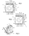
- La
figure 1 illustre, selon une vue en coupe, un dispositif de protection contre les surtensions lorsque la composant de protection est en service. - La
figure 2 illustre, selon une vue en coupe, le dispositif de protection représenté sur lafigure 1 lorsque le composant de connexion est déconnecté. - La
figure 3 illustre, selon une vue en perspective, un dispositif de protection conforme à l'invention pourvu de deux varistances montées en parallèle. - Les
figures 4a, 4b, 4c illustrent, selon une vue schématique, un système de visualisation de l'état de deux varistances montées en parallèle lorsque les deux varistances sont en service (figure 4a ), lorsqu'une seule des varistances est en service (figure 4b ) ou lorsque les deux varistances sont déconnectées (figure 4c ). - Les
figures 5a, 5b, 5c illustrent, selon une vue schématique, une variante améliorée du système de visualisation de l'état de deux varistances montées en parallèle lorsque les deux varistances sont en service (figure 5a ), lorsqu'une seule des varistances est en service (figure 5b ) ou lorsque les deux varistances sont déconnectées (figure 5c ). - Les
figures 6a, 6b, 6c illustrent, selon une vue schématique, une variante de dispositif de protection conforme à l'invention, dans laquelle le dispositif est adapté pour être raccordé à un système de signalisation à distance, les figures illustrant les deux états suivants : un premier état où les deux varistances sont en service (figure 6a ) et un deuxième état où une seule des varistances est en service (figures 6b et 6c ). - La
figure 7 illustre, selon une vue en perspective, une embase sur laquelle est destinée à être enfichée une cellule de protection conforme à l'invention. - La
figure 8 illustre, selon une vue en perspective, une variante préférentielle de réalisation du dispositif de protection conforme à l'invention, combinant un organe de visualisation directe et un indicateur signalétique déporté.
- The
figure 1 illustrates, in sectional view, an overvoltage protection device when the protection component is in use. - The
figure 2 illustrates, in a sectional view, the protective device represented on thefigure 1 when the connection component is disconnected. - The
figure 3 illustrates, in a perspective view, a protection device according to the invention provided with two varistors connected in parallel. - The
Figures 4a, 4b, 4c illustrate, in a schematic view, a system for visualizing the state of two varistors connected in parallel when the two varistors are in use (figure 4a ), when only one of the varistors is in use (figure 4b ) or when both varistors are disconnected (figure 4c ). - The
Figures 5a, 5b, 5c illustrate, in a schematic view, an improved variant of the system for visualizing the state of two varistors connected in parallel when the two varistors are in use (figure 5a ), when only one of the varistors is in use (figure 5b ) or when both varistors are disconnected (figure 5c ). - The
Figures 6a, 6b, 6c illustrate, in a schematic view, an alternative protection device according to the invention, wherein the device is adapted to be connected to a remote signaling system, the figures illustrating the following two states: a first state where the two varistors are in use (figure 6a ) and a second state where only one of the varistors is in use (Figures 6b and 6c ). - The
figure 7 illustrates, in a perspective view, a base on which is intended to be plugged a protection cell according to the invention. - The
figure 8 illustrates, in a perspective view, a preferred embodiment of the protection device according to the invention, combining a direct display member and a remote indicator.
Le dispositif de protection contre les surtensions conforme à l'invention est destiné à être branché en dérivation sur l'équipement ou l'installation électrique à protéger. L'expression « installation électrique » fait référence à tout type d'appareils ou réseaux susceptibles de subir des perturbations de tension, notamment des surtensions transitoires dues à la foudre. Dans ce dernier cas, il est donc formé par un parafoudre.The overvoltage protection device according to the invention is intended to be branched into the equipment or the installation electric to protect. The term " electrical installation " refers to any type of device or network that is susceptible to voltage disturbances, including transient overvoltages due to lightning. In the latter case, it is formed by a surge arrester.
Le dispositif de protection contre les surtensions conforme à l'invention est avantageusement destiné à être disposé entre une phase de l'installation à protéger et la terre.The overvoltage protection device according to the invention is advantageously intended to be disposed between a phase of the installation to be protected and the earth.
Il est par ailleurs envisageable, sans pour autant sortir du cadre de l'invention, que le dispositif, au lieu d'être branché en dérivation entre une phase et la terre, soit branché entre le neutre et la terre, entre la phase et le neutre, ou entre deux phases (cas d'une protection différentielle).It is also conceivable, without departing from the scope of the invention, that the device, instead of being connected bypass between a phase and the earth, is connected between the neutral and the earth, between the phase and the neutral, or between two phases (case of differential protection).
Le dispositif de protection comporte au moins un composant de protection 10 formant la partie active par exemple d'un parafoudre, destinée à protéger l'installation électrique.The protection device comprises at least one
Dans la suite de la description, on considère que chaque composant de protection 10 présent dans le dispositif est formé par une varistance, étant entendu que l'utilisation d'une varistance n'est indiquée qu'à titre d'exemple et ne constitue en aucune manière une limitation de l'invention.In the remainder of the description, it is considered that each
Le dispositif de protection conforme à l'invention comporte deux varistances 10, des moyens de déconnexion 20 de chaque varistance, sensibles à leur degré de vieillissement et adaptés pour déconnecter individuellement chaque varistance de l'installation électrique lorsque les varistances se trouvent dans un état dégradé.The protection device according to the invention comprises two
Le dispositif de protection conforme à l'invention comporte également des moyens de visualisation 30 de l'état de chaque varistance 10, reliés fonctionnellement aux moyens de déconnexion 20.The protection device according to the invention also comprises means 30 for visualizing the state of each
Avantageusement, le dispositif de protection est formé par une cellule de protection 1 pouvant comporter un ou plusieurs modules 2 contenant chacun une varistance 10 (
Dans les versions débrochables du dispositif illustrées sur les
Ainsi, l'un des pôles de la varistance 10 est connecté directement à un plot de connexion 8, l'autre pôle de la varistance étant relié à une électrode 4, laquelle est soudée aux moyens de connexion 20 qui sont en contact électrique permanent avec l'autre plot de connexion 9.Thus, one of the poles of the
Les moyens de déconnexion 20 sont de préférence formés par un déconnecteur thermique, tel que par exemple une lame de déconnexion 21 en contact thermique et électrique avec la varistance 10 associée, de telle, sorte que l'échauffement de la varistance, liée à l'arrivée en fin de vie de cette dernière, entraîne l'ouverture de la lame de déconnexion 21, isolant ainsi la varistance des lignes à protéger.The disconnecting means 20 are preferably formed by a thermal disconnector, such as for example a
Les moyens de déconnexion 20 sont ainsi susceptibles de se déplacer entre une position dite de fermeture, dans laquelle la varistance 10 est connectée au réseau ou à l'installation électrique et une position d'ouverture, dans laquelle la varistance 10 est déconnectée de l'installation électrique. Ces deux positions sont illustrées sur les
Avantageusement, la lame de déconnexion 21 s'étend entre deux extrémités 21 A, 21 B, l'une des extrémités 21 A étant de préférence fixée à l'aide d'une soudure thermofusible sur l'une des électrodes 4. L'extrémité 21 A de la lame de déconnexion 21 est ainsi de préférence soudée en contrainte, de telle sorte que lorsque la varistance 10 arrive en fin de vie, elle s'échauffe et entraîne la fusion ou la rupture de la soudure qui, une fois rompue, permet la libération de la lame de déconnexion 21.Advantageously, the
Grâce à son élasticité intrinsèque, la lame de déconnexion 21, précisément l'extrémité 21 A de la lame de déconnexion 21 s'écarte alors de l'électrode 4, tandis que l'autre extrémité 21 B reste fixe, tel que cela est représenté sur la
On va maintenant décrire en détails la structure des moyens de visualisation 30.The structure of the display means 30 will now be described in detail.
Les moyens de visualisation 30 sont adaptés pour informer un tiers de l'état de la ou des varistances contenues dans la cellule de protection 1. Ces moyens de visualisation 30 sont reliés fonctionnellement aux moyens de déconnexion 20, c'est-à-dire qu'il existe des moyens intermédiaires permettant de relier la position des moyens de déconnexion 20 à l'indication fournie par les moyens de visualisation 30.The display means 30 are adapted to inform a third party of the state of the varistors or varistors contained in the
Les moyens de visualisation 30 comportent, pour chaque cellule de protection 1, une pièce de commande 40, distincte des moyens de déconnexion 20 et apte à se déplacer sous la dépendance de ces derniers. Cette pièce de commande 40 assure avantageusement la liaison fonctionnelle entre les moyens de déconnexion 20 et les moyens de visualisation 30.The display means 30 comprise, for each
Les moyens de visualisation 30 comportent également un moyen d'indication 50 de l'état de la varistance 10 associé à la pièce de commande 40, de telle manière que le moyen d'indication 50 indique, en fonction de la position de la pièce de commande 40, si la varistance 10 est en service ou déconnectée.The display means 30 also comprise means 50 for indicating the state of the
La pièce de commande 40 et les moyens de déconnexion 20 sont disposés relativement de telle manière que lors de l'ouverture des moyens de déconnexion 20, ces derniers libèrent la pièce de commande 40 autorisant ainsi le déplacement libre, c'est-à-dire non contrôlé par les moyens de déconnexion 20, de cette dernière.The
Une fois libérée, la pièce de commande 40 est ainsi libre de se déplacer, c'est à dire qu'elle n'est ni actionnée, ni guidée en déplacement par les moyens de déconnexion 20.Once released, the
De façon particulièrement avantageuse, les moyens de déconnexion 20 sont, dans leur position de fermeture, montés de manière à former une butée à l'encontre de la pièce de commande 40. Ainsi, la pièce de commande 40 comporte avantageusement une zone d'appui 40A qui, lorsque les moyens de déconnexion 20 sont dans leur position de fermeture, vient en appui contre ces derniers (
La lame de déconnexion 21 assume donc une triple fonction :
- en fonctionnement normal, elle sert à la liaison électrique de la varistance 10,
- en fin de vie de la varistance 10, elle sert à déconnecter cette dernière,
- enfin, elle sert également à libérer les moyens de visualisation 30 conduisant ainsi à un changement d'indication de l'état de la varistance 10.
- in normal operation, it serves for the electrical connection of the
varistor 10, - end of life of the
varistor 10, it is used to disconnect the latter, - finally, it also serves to release the display means 30 thus leading to a change of indication of the state of the
varistor 10.
Avantageusement, la pièce de commande 40 et les moyens de déconnexion 20 sont disposés de telle sorte que lorsque les moyens de déconnexion 20 sont dans leur position de fermeture (
Les moyens de visualisation 30 assument donc une double fonction :
- d'une part, ils permettent, par l'intermédiaire du moyen d'indication 50, de fournir une indication sur l'état de la varistance 10,
- et d'autre part, ils participent, par le biais de la pièce de commande 40, à la déconnexion de la varistance 10 en forçant les moyens déconnexion 20, notamment la lame de déconnexion 21, vers leur position d'ouverture.
- on the one hand, they allow, by means of the indication means 50, to provide an indication of the state of the
varistor 10, - and on the other hand, they participate, through the
control part 40, the disconnection of thevaristor 10 by forcing the disconnection means 20, including thedisconnection blade 21, to their open position.
Un tel montage permet donc d'anticiper et de sécuriser la déconnexion du composant de protection. Il permet également d'avoir recours à une lame de déconnexion 21 présentant un effet ressort modéré et donc de diminuer les risques de fragilisation mécanique de la soudure de déconnexion thermique.Such an arrangement therefore makes it possible to anticipate and secure the disconnection of the protection component. It also makes it possible to use a
La conception du dispositif de protection et en particulier le montage des moyens de visualisation 30 de l'état de la varistance permet ainsi, grâce au faible nombre de pièces coopérant ensemble et au nombre limité de points de contact entre ces pièces d'assurer une déconnexion rapide et fiable du composant de protection. Cette fiabilité est encore accentuée par le fait que les moyens de visualisation 30 sont districts des moyens de déconnexion 20.The design of the protection device and in particular the mounting of the display means 30 of the state of the varistor allows thus, thanks to the small number of parts cooperating together and the limited number of contact points between these parts to ensure a fast and reliable disconnection of the protection component. This reliability is further accentuated by the fact that the display means 30 are districts of the disconnection means 20.
En outre, grâce au déplacement simultané ou quasi-simultané des moyens de visualisation 30 et des moyens de déconnexion 20, un tiers peut s'apercevoir très rapidement qu'une varistance est déconnectée.In addition, thanks to the simultaneous or almost simultaneous movement of the display means 30 and the disconnection means 20, a third party can realize very quickly that a varistor is disconnected.
De façon particulièrement avantageuse, et tel que cela est représenté sur les
Avantageusement, la partie frontale 41A du curseur 41 est spécifiquement conçue pour venir en appui contre les moyens de déconnexion 20, d'une part lorsque ces derniers sont dans leur position de fermeture et d'autre part, lors de l'ouverture de ces derniers, de telle sorte que le curseur 41 soit en permanence en contact avec les moyens de déconnexion 20.Advantageously, the
Selon la variante de réalisation représentée sur les
De façon particulièrement avantageuse, les moyens de visualisation 30 comportent également un moyen élastique 70, du genre ressort, adapté pour exercer une force de rappel sur la pièce de commande 40 responsable du déplacement de cette dernière.Particularly advantageously, the display means 30 also comprise a resilient means 70, spring-like, adapted to exert a restoring force on the
Tel que cela est représenté sur les
Le moyen élastique 70 est ainsi avantageusement adapté pour occuper une position comprimée lorsque la pièce de commande 40 est contrainte longitudinalement, c'est-à-dire suivant une direction sensiblement parallèle à la direction de déplacement F et une position de repos, lorsque la pièce de commande 40 est libérée des moyens de déconnexion 20 (
Selon le mode de réalisation illustré sur les
Lorsque la soudure rompt, par exemple sous l'effet de l'échauffement de la varistance 10, l'extrémité 21A de la lame de déconnexion 21 se déplace selon la direction F et ne constitue donc plus un obstacle ou une butée à l'encontre de la pièce de commande 40. Le moyen élastique 70, initialement comprimé, tend alors à se détendre (
Selon ce mode de réalisation , le moyen d'indication 50 est avantageusement formé par un organe de visualisation, de préférence par un panneau 51, par exemple rectangulaire, préférentiellement disposé sur le curseur 41. Le panneau 51 peut être formé par une pièce en matériau plastique isolant, par exemple collée sur le curseur 41, mais peut également être simplement formé par une bande colorée peinte sur le curseur 41. Le panneau 51, est de plus avantageusement disposé de manière à se déplacer en même temps que la pièce de commande 40 en regard d'une fenêtre 61 ménagée dans l'une des faces 60B du boîtier 60 située à l'opposé du socle 3, pour obtenir un aspect visuel différent à travers la fenêtre 61, en fonction de la position de la pièce de commande 40.According to this embodiment, the indication means 50 is advantageously formed by a display member, preferably by a
Ainsi, lorsque les moyens de déconnexion 20 sont en position de fermeture (
Au contraire, lorsque les moyens de déconnexion 20 sont en position ouverte comme cela est représenté sur la
Selon un mode de réalisation de l'invention, représenté sur la
Selon ce mode de réalisation, les moyens de visualisation 30 sont de préférence reliés fonctionnellement au premier et au deuxième moyens de déconnexion 20A, 20B de manière à fournir une indication différenciée sur l'état de chaque varistance 10 prise individuellement (
Selon ce mode de réalisation, la pièce de commande 40 est de préférence formée par un curseur 41, pourvu d'une partie frontale 41A, monté mobile élastiquement entre :
- une position initiale (
figure 4a ), correspondant à un état connecté des deux composants de protection, dans laquelle le curseur 41 est maintenu en position simultanément par les deux moyens de connexion 20A, 20B, sa partie frontale 41 A venant en appui contre ces derniers, - une position intermédiaire (
figure 4b ) décalée par rapport à la position initiale, correspondant à un état où un seul des moyens de déconnexion 20A, 20B est déconnecté, dans laquelle le curseur 41 est maintenu en position par le moyen de déconnexion 20A en position de fermeture, - et une position finale (
figure 4c ) décalée par rapport à la position intermédiaire, correspondant à un état déconnecté des deux moyens de déconnexion 20A, 20B. Dans cette position finale, le curseur 41 n'est pas nécessairement maintenu en position par les moyens de déconnexion 20A, 20B mais peut venir en butée contre ces derniers, tel que cela est représenté sur lafigure 4c .
- an initial position (
figure 4a ), corresponding to a connected state of the two protection components, in which theslider 41 is held in position simultaneously by the two connection means 20A, 20B, itsfront portion 41 A bearing against these, - an intermediate position (
figure 4b ) offset from the initial position, corresponding to a state where only one of the disconnecting means 20A, 20B is disconnected, in which theslider 41 is held in position by the disconnecting means 20A in the closed position, - and a final position (
figure 4c ) offset from the intermediate position, corresponding to a disconnected state of the two disconnecting means 20A, 20B. In this final position, theslider 41 is not necessarily held in position by the disconnection means 20A, 20B but can abut against them, as shown in FIG.figure 4c .
Selon ce mode de réalisation de l'invention, le moyen d'indication 50 est préférentiellement formé par un organe de visualisation, de préférence un panneau 51 monté sur ou venu de matière avec le curseur 41 et disposé de préférence vers l'extrémité opposée à la partie frontale 41 A de manière à se déplacer en regard de la fenêtre de visualisation 61.According to this embodiment of the invention, the indication means 50 is preferably formed by a display member, preferably a
Le panneau 51 est préférentiellement divisé en deux zones 51 A, 51 B disposées de telle sorte que lorsque les moyens de déconnexion 20A, 20B sont en position de fermeture (
L'amplitude de déplacement du curseur 41 est donc ajustée de manière à générer un aspect visuel différent à travers la fenêtre 61 en fonction de la configuration des moyens de déconnexion 20A, 20B.The amplitude of displacement of the
Selon le mode de réalisation illustré sur les
De façon particulièrement avantageuse, la pièce de commande 40, précisément le curseur 41, comporte deux étages de zone d'appui 42, 43 disposés l'un derrière l'autre suivant la direction de déplacement F de la pièce de commande 40 de manière à assurer le blocage de cette dernière successivement dans les deux positions initiale et intermédiaire. La structure de la pièce de commande 40 permet ainsi de générer un déplacement par paliers de cette dernière entre les différentes positions initiale, intermédiaire et finale.In a particularly advantageous manner, the
De façon encore plus préférentielle, la pièce de commande 40 comporte une paire de zones d'appui dites aval 42A, 42B destinées à venir en butée, dans la position initiale (
La pièce de commande 40 comporte également une paire de zones d'appui dites amont 43A, 43B, disposées en amont de la première paire de zones d'appui aval 42A, 42B en regard du sens de déplacement F de la pièce de commande 40, de telle sorte que dans la position intermédiaire (
Bien évidemment, si l'ouverture de l'autre moyen de déconnexion 20B avait eu lieu en premier, c'est l'autre zone d'appui amont 43B qui serait venue en butée contre le moyen de déconnexion 20B correspondant.Of course, if the opening of the other 20B disconnection means had taken place first, it is the other
Dans cette configuration, les moyens de visualisation 30 présentent avantageusement une symétrie par rapport au plan S délimitant la séparation entre les deux varistances.In this configuration, the display means 30 advantageously have a symmetry with respect to the plane S delimiting the separation between the two varistors.
De façon particulièrement avantageuse, les zones d'appui amont 43A, 43B sont préférentiellement formées par des doigts 44 faisant saillie de part et d'autre de la pièce de commande 40 et s'étendant suivant une direction sensiblement perpendiculaire à la direction principale F de déplacement de la pièce de commande 40.Particularly advantageously, the
De façon préférentielle, le dispositif comporte des moyens de guidage en déplacement de la pièce de commande 40, adaptés pour autoriser un débattement angulaire de cette dernière de manière permettre, lors de l'ouverture de l'un des moyens de déconnexion 20A, 20B, le franchissement de l'autre moyen de déconnexion 20A, 20B, par la zone d'appui aval 42A, 42B correspondante. Les moyens de guidage en déplacement peuvent avantageusement être formés par les parois latérales 60C, 60D du boîtier 60. Le curseur 41 est alors avantageusement disposé au sein du boîtier 60 de manière à maintenir un jeu suffisant entre les contours du curseur 41 et les parois 60C, 60D pour autoriser un débattement angulaire.Preferably, the device comprises guiding means in displacement of the
Ainsi, pour passer de la position initiale représentée sur la
Afin de faciliter encore le franchissement du moyen de déconnexion 20A resté en position de fermeture par le curseur 41, ce dernier est pourvu de moyens de dégagement 45. Les moyens de dégagement 45 sont préférentiellement formés par des découpes obliques, ménagées de part et d'autre du curseur 41, au niveau de sa partie frontale 41 A, lesdites découpes formant ainsi les zones d'appui aval 42A, 42B.To further facilitate the crossing of the disconnection means 20A remained in the closed position by the
De la même façon que dans le mode de réalisation précédemment décrit et illustré sur les
Un autre mode de réalisation de l'invention va maintenant être décrit en se référant aux
Selon ce mode de réalisation, les moyens de visualisation 30, comportent avantageusement des moyens de guidage 80 adaptés pour assurer le déplacement de la pièce de commande 40 selon une trajectoire prédéterminée formée par la combinaison d'un mouvement de rotation et d'un mouvement de translation.According to this embodiment, the display means 30 advantageously comprise guide means 80 adapted to ensure the displacement of the
La pièce de commande 40 est contrainte élastiquement par l'intermédiaire du moyen élastique 70 interposé entre d'une part la pièce de commande 40 et d'autre part une butée 62 montée de façon fixe au sein du boîtier 60.The
Sous l'action du moyen élastique 70, du genre ressort, la pièce de commande 40 vient en appui contre les moyens de déconnexion 20A, 20B. La pièce de commande 40 comporte à cet effet deux parties d'extrémités 46A, 46B par exemple en forme de plots saillants, adaptées pour venir en appui contre chacun des moyens de déconnexion 20A, 20B lorsque ces derniers sont en position de fermeture (
Les moyens de guidage 80 de la pièce de commande 40 sont avantageusement formés par un ergot 81, de préférence disposé sur la pièce de commande 40, et une gorge 82 correspondante, de préférence en forme de V, au sein de laquelle l'ergot 81 est susceptible de se déplacer lorsque la pièce de commande 40 passe successivement dans les différentes positions initiale, intermédiaire et finale illustrées sur les
Le fonctionnement de cette variante de réalisation est le suivant.The operation of this variant embodiment is as follows.
Dans la position initiale illustrée sur la
Lorsque l'un des moyens de déconnexion 20B vient en position d'ouverture, il libère au moins partiellement la pièce de commande 40 qui est alors susceptible de se déplacer en rotation suivant un angle β jusqu'à ce qu'elle vienne au contact de l'une des parois 60D du boîtier 60, tel que cela est illustré sur la
Dans cette position intermédiaire, la pièce de commande 40 est également dans une position stable et vient toujours en appui élastique contre l'autre moyen de déconnexion 20A, par l'intermédiaire de sa partie d'extrémité 46A. Le déplacement de la pièce de commande 40 entre la position initiale (
Selon ce mode de réalisation, le moyen d'indication 50 est préférentiellement formé par un organe de visualisation, tel qu'un panneau de visualisation 51 disposé de préférence à l'une des extrémités de la pièce de commande 40 de manière à se déplacer en regard de la fenêtre 61 ménagée dans le boîtier 60. Ainsi, dans la position initiale représentée sur la
Dans la position intermédiaire illustrée sur la
Lorsque l'autre moyen de déconnexion 20A passe à son tour en position d'ouverture, la pièce de commande 40, sous l'action du moyen élastique 70, tend à se déplacer suivant une direction F sensiblement rectiligne ce qui a pour effet de dégager complètement la fenêtre de visualisation 61 qui présente alors un aspect visuel homogène, par exemple rouge, indiquant que tous les composants de protection sont déconnectés et qu'il doivent être remplacés.When the other 20A disconnection means in turn turn in the open position, the
Le déplacement de la pièce de commande 40 entre les positions intermédiaire et finale est guidé par la coopération de l'ergot 81 avec la gorge 82, l'ergot 81 se déplaçant de manière sensiblement rectiligne dans l'une des branches du V formé par la gorge 82.The displacement of the
Un tel montage présente l'avantage de ne pas entraver la déconnexion en cas de blocage des moyens de visualisation 30.Such an arrangement has the advantage of not hinder disconnection in case of blocking of the display means 30.
Un autre avantage de ce montage est qu'il permet également de participer à la déconnexion par l'intermédiaire du moyen élastique 70 qui, en exerçant une poussée sur la pièce de commande 40, favorise le déplacement des moyens de déconnexion 20A, 20B au moment de la fusion de la soudure. Un autre avantage de ce montage est qu'il est peu sensible aux vibrations ou aux chocs susceptibles de se produire par exemple pendant les opérations de transport, la pièce de commande 40 étant toujours susceptible de retrouver sa position initiale sous l'effet de la force de rappel exercée par le moyen élastique 70.Another advantage of this arrangement is that it also makes it possible to participate in the disconnection via the elastic means 70 which, by exerting a thrust on the
Selon un autre mode de réalisation de l'invention illustré sur les
En revanche, contrairement aux différents modes de réalisation précédemment décrits le moyen d'indication 50 n'est pas relié mécaniquement à la pièce de commande 40, mais déporté, c'est-à-dire qu'il est relié à cette dernière par d'autres moyens que des moyens mécaniques, notamment par télésignalisation. Ainsi, l'indicateur n'est pas situé à proximité directe du boîtier 60 mais à une distance non négligeable de ce dernier.On the other hand, contrary to the various embodiments previously described, the indication means 50 is not mechanically connected to the
Cette variante de réalisation du dispositif est représentée dans le cas de deux varistances montées en parallèle mais peut bien évidement s'appliquer à des dispositifs ne comportant qu'une seule varistance.This variant embodiment of the device is represented in the case of two varistors connected in parallel, but can of course be applied to devices having only one varistor.
Selon ce mode de réalisation, la pièce de commande 40 est solidarisée avec deux picots 52, 53 destinés à venir s'engager dans des logements 401, 402 correspondants ménagés dans une embase 400 (
Au contraire, lorsque l'une des varistances est déconnectée, tel que cela est illustré sur la
Selon une caractéristique particulièrement avantageuse de l'invention, la pièce de commande 40 est solidarisée avec les picots 52, 53 de telle sorte que son déplacement entraîne dans le même temps un mouvement sensiblement identique des picots 52, 53 au sein de passages 62, 63 ménagés dans la paroi inférieure 60A du boîtier 60.According to a particularly advantageous characteristic of the invention, the
De façon particulièrement avantageuse, la pièce de commande 40 peut être formée par un curseur, et se présente préférentiellement sous la forme d'une tige allongée pourvue d'une partie frontale 40A en forme de disque ou de sphère destinée à venir en appui contre une pliure 20C ménagée dans les moyens de déconnexion 20A, 20B, et conçue pour former une butée à l'encontre de la pièce de commande 40.In a particularly advantageous manner, the
Lors de leur ouverture, les moyens de déconnexion 20A, 20B libèrent la pièce de commande 40, autorisant ainsi le libre déplacement de cette dernière. Au contraire, lorsque les moyens de déconnexion 20A, 20B sont en positions de fermeture (
Les pliures 20C s'étendent préférentiellement suivant un plan sensiblement perpendiculaire au plan d'extension des lames de déconnexion 21. De façon encore plus préférentielle, les pliures 20C peuvent s'étendre en oblique par rapport aux lames des déconnexions 21, de telle sorte que la partie frontale 40A de la pièce de commande 40 exerce sur ces dernières une contrainte motrice tendant à repousser les lames de déconnexion 21 vers leur position d'ouverture. "The
La pièce de commande 40 et le moyen élastique 70 associé constituent alors des moyens d'aide à la déconnexion des composants de protection du dispositif.The
De façon particulièrement avantageuse, la pièce de commande 40 est suffisamment flexible pour autoriser un débattement angulaire de sa partie frontale 40A. En effet, tel que cela est représenté sur les
Le principe de fonctionnement du dispositif va maintenant être précisé en se référant aux
Lorsque les deux moyens de déconnexion 20A, 20B, précisément les lames de déconnexion 21 sont en position de fermeture tel qu'illustré à la
Lors de son déplacement de la position initiale vers la position finale, la pièce de commande 40 entraîne simultanément les picots 52, 53 hors de leurs logements 401, 402 au sein de l'embase 400, déclenchant ainsi la commande d'un nouveau signal à distance indiquant que l'une au moins des varistances du dispositif est déconnectée.During its displacement from the initial position to the final position, the
Selon un mode de réalisation encore plus préférentiel de l'invention, illustré sur la
A cet effet, le dispositif comporte une première pièce de commande 403, associée à un organe de visualisation direct du genre panneau de visualisation 51, ainsi qu'une deuxième pièce de commande 404, associée à un indicateur signalétique déporté (non représenté), la première et la deuxième pièces de commande 403, 404 étant adaptées pour coopérer indépendamment l'une de l'autre avec les moyens de déconnexion 20A, 20B. Ainsi, le montage associant la première pièce de commande 403 avec l'organe de visualisation directe pourra du type être illustré aux
Selon cette variante de réalisation de l'invention, l'ouverture des moyens de déconnexion 20A, 20B entraîne de façon quasi-simultanée la libération des première et deuxième pièces de commande 403, 404, indiquant ainsi qu'au moins une varistance est déconnectée, et ce d'une part par le biais du panneau de visualisation 51 et d'autre part via l'indicateur signalétique déporté.According to this embodiment of the invention, the opening of the disconnection means 20A, 20B almost simultaneously causes the release of the first and
Un tel dispositif permet donc d'associer au sein d'un même boîtier 60, deux pièces de commande 403, 404 distinctes, et susceptibles d'actionner deux moyens d'indication complémentaires de l'état des composants de protection, à savoir un moyen d'indication de proximité, se présentant par exemple sous la forme d'un panneau de visualisation 51, et un moyen d'indication à distance, se présentant avantageusement sous la forme d'un indicateur signalétique déporté, par exemple visuel ou encore sonore.Such a device thus makes it possible to associate within the
Le dispositif de protection conforme à l'invention permet donc, grâce à un montage particulièrement simple des moyens de visualisation 30 d'assurer non seulement une déconnexion fiable et efficace des varistances lorsque ces dernières se trouvent dans un état dégradé, mais également de permettre simultanément à un tiers de visualiser l'état de ces varistances, et ce en limitant le risque de grippage du mécanisme ou encore d'éventuels problèmes de guidage de pièces.The protection device according to the invention thus makes it possible, thanks to a particularly simple mounting of the display means 30, to ensure not only a reliable and efficient disconnection of the varistors when the latter are in a degraded state, but also to enable simultaneously to a third to visualize the state of these varistors, and this by limiting the risk of seizure of the mechanism or possible problems of guiding parts.
En effet, en raison de la faible surface de contact entre les pièces fonctionnelles, le risque de blocage d'une pièce par une autre est significativement réduit.Indeed, due to the small contact surface between the functional parts, the risk of blocking a part by another is significantly reduced.
L'invention trouve son application dans les dispositifs électriques de protection contre les surtensions transitoires.The invention finds its application in electrical devices for protection against transient overvoltages.
Claims (21)
- A device for protecting an electrical installation against voltage surges, comprising:- two protection components (10) connected in parallel, respectively associated with first and second disconnector means (20, 20A, 20B) for the respective protection component (10), adapted to disconnect the latter from the electrical installation and suitable for moving between a closed position in which the respective protection component (10) is connected, and an open position in which the respective protection component (10) is disconnected;- display means (30) for indicating the state of the protection components (10), functionally connected to the disconnector means (20, 20A, 20B), and comprising:- at least one control part (40) distinct from the disconnector means (20, 20A, 20B) and suitable for moving under the dependency thereof; and- at least one indicator means (50) for indicating the state of the protection components (10) associated with the control part (40) in such a manner that the indicator means (50) indicates whether the protection components (10) are in operation or disconnected, as a function of the position of the control part (40);the display means (30) means being functionally connected to the first and second disconnector means (20A, 20B) in such a manner as to provide distinguishable indications about the states of each of the protection components (10) taken individually, characterised in that
the control part (40) and the disconnector means (20, 20A, 20B) are relatively disposed in such a manner that during opening of the disconnector means (20, 20A, 20B) the latter release the control part (40) thus allowing the control part to move, and
in which the control part (40) is mounted to move resiliently between- an initial position that corresponds to a state in which both protection components (10) are connected, said control part (40) being held in position by both disconnector means (20A, 20B);- an intermediate position which is offset from the initial position and corresponds to a state in which only one of the disconnector means (20A, 20B) is disconnected, in which the control part (40) is held in position by the disconnector means (20A, 20B) in the closed position; and- a final position which is offset from the intermediate position and corresponds to a state in which both of the disconnector means (20A, 20B) are disconnected. - The device of claim 1, characterised in that, in the closed position, the disconnector means (20, 20A, 20B) are mounted so as to form an abutment against the control part (40).
- The device of claim 1 or 2, characterised in that the control part (40) and the disconnector means (20, 20A, 20B) are disposed in such a manner that when the disconnector means (20, 20A, 20B) are in the closed position, the control part (40) is resiliently stressed and comes to bear against the disconnector means (20, 20A, 20B), thereby exerting driving stress thereagainst, tending to push them towards the open position.
- The device according to any one of claims 1 to 3, characterised in that the control part (40) is constituted by a slider (41) suitable for moving in a substantially rectilinear direction and having a front portion (41A) designed to bear against the disconnector means (20, 20A, 20B).
- The device according to claim 3 or 4, characterised in that the display means (30) include resilient means (70) adapted to exert a return force on the control part (40) for causing the latter to move.
- The device according to any one of the preceding claims, characterised in that the control part (40) includes two stages of bearing regions (42, 43) disposed one behind the other in the travel direction (F) of the control part (40) so as to hold the control part (40) successively in the initial position and in the intermediate position.
- The device of claim 6, characterised in that the control part (40) includes a pair of downstream bearing regions (42A, 42B) for coming into abutment in the initial position against the two disconnector means (20A, 20B), and a pair of upstream bearing regions (43A, 43B) disposed upstream from the downstream pair of bearing regions in the travel direction of the control part , in such a manner that, in the intermediate position, one of the upstream bearing regions (43A, 43B) comes into abutment against the corresponding disconnector means (20A, 20B) that has remained in the closed position.
- The device of claim 7, characterised in that the upstream bearing regions (43A, 43B) are formed by fingers (44) projecting from either side of the control part (40) and extending in a direction that is substantially perpendicular to the main travel direction of the control part (40).
- The device of claim 7 or claim 8, characterised in that the device includes means for guiding the movement of the control part (40), said means being adapted to allow said control part (40) to move angularly sufficiently to allow, upon one of the disconnector means (20A, 20B) opening, the other disconnector means to be passed by one of the downstream bearing regions (42A, 42B).
- The device of claim 9, characterised in that the control part (40) is provided with disengagement means (45) arranged, on the control part (40) going from the initial position towards an intermediate position, to facilitate going past the disconnector means (20A, 20B) that has remained in the closed position.
- The device of claim 10, characterised in that the disengagement means (45) are formed by sloping recesses formed on either side of the control part (40) at the end thereof, and constituting the downstream bearing regions (42A, 42B).
- The device according to any one of the preceding claims, characterised in that it includes guide means (80) adapted to cause the control part (40) to move along a predetermined path formed by a combination of a movement in rotation and a movement in translation.
- The device of claim 12, characterised in that the guide (80) means are formed by a stud (81) placed on the control part (40) and a corresponding V-shaped groove (82) within which the stud (81) can move.
- The device of any one of claims 1, characterised in that the indicator means (50) is formed by at least one display member, preferably a display panel (51), associated with the control part in such a manner as to move in register with a window (61) formed in the housing (60) of the device so as to obtain a different visual appearance through the window (61) as a function of the position of the control part (40).
- The device according to one of claims 1 to 5, characterised in that the indicator means (50) is constituted by a remote indicator, functionally connected to the control part (40) via a remote-signaling system.
- The device of claim 15, characterised in that the control part (40) is sufficiently flexible to allow its front portion (40A) to move angularly.
- The device of claim 16, characterised in that the control part (40) includes a narrowing of section imparting a flexible nature thereto.
- The device according to one of claims 15 to 17, characterised in that the front portion (40A) of the control part (40) is in the form of a sphere for bearing against a fold (20C) formed in the disconnector means (20A, 20B), said fold (20C) being designed to form an abutment against the control part (40).
- The device according to any one of the preceding claims, characterised in that the protection component (10) is formed by a varistor.
- The device according to any one of the preceding claims, characterised in that each disconnector means (20A, 20B) is formed by a disconnector blade (21) soldered to one of the poles of the corresponding protection component (10), and is suitable for moving under the force of resilient return drive from the closed position to the open position after the solder has melted, thereby releasing the control part (40).
- The device according to one of the preceding claims, characterised in that it further comprises a first control part (403) associated with a direct display member, and a second control part (404) associated with a remote-signaling display means (30), the first and second control parts (403, 404) being adapted to co-operate independently of each other with the disconnector means (20, 20A, 20B).
Applications Claiming Priority (1)
| Application Number | Priority Date | Filing Date | Title |
|---|---|---|---|
| PCT/FR2004/000960 WO2005112211A1 (en) | 2004-04-19 | 2004-04-19 | Surge voltage protection device with improved disconnection and visual indication means |
Publications (2)
| Publication Number | Publication Date |
|---|---|
| EP1745533A1 EP1745533A1 (en) | 2007-01-24 |
| EP1745533B1 true EP1745533B1 (en) | 2012-06-06 |
Family
ID=34958053
Family Applications (1)
| Application Number | Title | Priority Date | Filing Date |
|---|---|---|---|
| EP04742540A Expired - Lifetime EP1745533B1 (en) | 2004-04-19 | 2004-04-19 | Surge voltage protection device with improved disconnection and visual indication means |
Country Status (8)
| Country | Link |
|---|---|
| US (1) | US7684166B2 (en) |
| EP (1) | EP1745533B1 (en) |
| CN (1) | CN100566056C (en) |
| BR (1) | BRPI0418761A (en) |
| CA (1) | CA2563552A1 (en) |
| ES (1) | ES2386546T3 (en) |
| MX (1) | MXPA06012057A (en) |
| WO (1) | WO2005112211A1 (en) |
Families Citing this family (42)
| Publication number | Priority date | Publication date | Assignee | Title |
|---|---|---|---|---|
| FR2897989B1 (en) | 2006-02-24 | 2008-05-09 | Soule Prot Surtensions Sa | OVERVOLTAGE PROTECTION DEVICE WITH SIMPLIFIED VISUALIZATION SYSTEM AND METHOD OF MANUFACTURING THE SAME |
| DE102007030653B4 (en) * | 2007-07-02 | 2017-04-13 | Phoenix Contact Gmbh & Co. Kg | Snubber |
| DE102008048644B4 (en) * | 2008-08-01 | 2017-08-24 | DEHN + SÖHNE GmbH + Co. KG. | Overvoltage protection device with one or more parallel-connected, located in a structural unit overvoltage limiting elements |
| DE102009022069B4 (en) * | 2009-01-12 | 2016-10-20 | Dehn + Söhne Gmbh + Co. Kg | Surge arresters |
| DE102009036125A1 (en) * | 2009-08-05 | 2011-02-10 | Phoenix Contact Gmbh & Co. Kg | Snubber |
| DE102009053145A1 (en) * | 2009-11-05 | 2011-05-12 | Phoenix Contact Gmbh & Co. Kg | Overvoltage protection device, has thermal expandable material arranged within housing such that pole of varistor does not stay in electrically conductive contact with connection elements |
| DE102010010980A1 (en) * | 2010-03-10 | 2011-09-15 | Phoenix Contact Gmbh & Co. Kg | Snubber |
| FR2958789B1 (en) * | 2010-04-09 | 2012-05-11 | Abb France | DEVICE FOR PROTECTION AGAINST TRANSIENT OVERVOLTAGES WITH IMPROVED THERMAL DISCONNECTOR |
| DE102010015814B4 (en) * | 2010-04-20 | 2014-08-07 | Phoenix Contact Gmbh & Co. Kg | Snubber |
| US9147510B2 (en) | 2010-04-20 | 2015-09-29 | Phoenix Contact Gmbh & Co. Kg | Overvoltage protection element |
| CN101887790B (en) * | 2010-06-13 | 2012-07-04 | 深圳科安达电子科技股份有限公司 | Piezoresistor for lightning protection |
| CN102377176A (en) * | 2010-08-13 | 2012-03-14 | 施耐德电器工业公司 | Surge protection device |
| DE102011018556A1 (en) * | 2011-02-18 | 2012-08-23 | Dehn + Söhne Gmbh + Co. Kg | Overvoltage protection device comprising at least one surge arrester |
| CZ304868B6 (en) * | 2011-04-01 | 2014-12-17 | Saltek S.R.O. | Surge voltage protector with exchangeable overvoltage protection module |
| EP2541579B1 (en) * | 2011-06-30 | 2015-11-04 | Epcos Ag | Electric device |
| CN103094013B (en) * | 2011-11-07 | 2015-12-23 | 施耐德电器工业公司 | The tripping mechanism of surge protector and surge protector |
| US8743525B2 (en) | 2012-06-19 | 2014-06-03 | Raycap Intellectual Property, Ltd | Overvoltage protection devices including wafer of varistor material |
| DE102013006052B4 (en) * | 2013-02-08 | 2016-08-04 | DEHN + SÖHNE GmbH + Co. KG. | Surge protection device |
| DE102013022348B4 (en) * | 2013-10-22 | 2016-01-07 | Dehn + Söhne Gmbh + Co. Kg | Overvoltage protection device comprising at least one surge arrester and a thermally triggered switching device connected in series with the surge arrester |
| US20170110279A1 (en) * | 2014-04-07 | 2017-04-20 | Littelfuse, Inc. | Thermal metal oxide varistor circuit protection device |
| US9906017B2 (en) | 2014-06-03 | 2018-02-27 | Ripd Research And Ip Development Ltd. | Modular overvoltage protection units |
| TWM514689U (en) * | 2015-08-28 | 2015-12-21 | 蘇州市台基防雷科技有限公司 | Side-elastic surge absorber module |
| US10319545B2 (en) | 2016-11-30 | 2019-06-11 | Iskra Za{hacek over (s)}{hacek over (c)}ite d.o.o. | Surge protective device modules and DIN rail device systems including same |
| US10707678B2 (en) | 2016-12-23 | 2020-07-07 | Ripd Research And Ip Development Ltd. | Overvoltage protection device including multiple varistor wafers |
| US10447026B2 (en) | 2016-12-23 | 2019-10-15 | Ripd Ip Development Ltd | Devices for active overvoltage protection |
| US10340110B2 (en) * | 2017-05-12 | 2019-07-02 | Raycap IP Development Ltd | Surge protective device modules including integral thermal disconnect mechanisms and methods including same |
| US10388479B2 (en) * | 2017-06-27 | 2019-08-20 | Shanghai Chenzhu Instrument Co., Ltd. | Surge protector, and release mechanism and base thereof |
| US10685767B2 (en) | 2017-09-14 | 2020-06-16 | Raycap IP Development Ltd | Surge protective device modules and systems including same |
| KR101985499B1 (en) * | 2017-12-28 | 2019-06-03 | 삼화콘덴서공업 주식회사 | Over-current protected metal oxide varistor |
| TWI848960B (en) | 2018-07-23 | 2024-07-21 | 加拿大商Ifd科技股份有限公司 | Temperature sensor and indicator |
| US11223200B2 (en) | 2018-07-26 | 2022-01-11 | Ripd Ip Development Ltd | Surge protective devices, circuits, modules and systems including same |
| DE102020107318B4 (en) * | 2020-03-17 | 2023-06-22 | Dehn Se | Surge protection device as well as modular surge protection system |
| CN214588697U (en) * | 2021-04-16 | 2021-11-02 | 厦门赛尔特电子有限公司 | Surge protection device with double tripping mechanisms |
| US11862967B2 (en) | 2021-09-13 | 2024-01-02 | Raycap, S.A. | Surge protective device assembly modules |
| US11723145B2 (en) | 2021-09-20 | 2023-08-08 | Raycap IP Development Ltd | PCB-mountable surge protective device modules and SPD circuit systems and methods including same |
| US11990745B2 (en) | 2022-01-12 | 2024-05-21 | Raycap IP Development Ltd | Methods and systems for remote monitoring of surge protective devices |
| US12506334B2 (en) | 2022-01-24 | 2025-12-23 | Raycap IP Development Ltd | Surge protective device modules and assemblies |
| US12199412B2 (en) | 2022-06-02 | 2025-01-14 | Ripd Ip Development Ltd. | Surge protective devices, circuits, modules and systems including same |
| CN115359981B (en) * | 2022-09-06 | 2024-05-24 | 福建省乔光电子科技有限公司 | Thermal protection piezoresistor module |
| US12206234B2 (en) | 2022-09-20 | 2025-01-21 | Ripd Ip Development Ltd | Overvoltage protection device modules |
| US12437906B2 (en) | 2022-10-18 | 2025-10-07 | Raycap, S.A. | Surge protective devices |
| US12580381B2 (en) | 2023-12-04 | 2026-03-17 | Ripd Ip Development Ltd | Overvoltage protection device modules and sheath bonding systems including same |
Family Cites Families (5)
| Publication number | Priority date | Publication date | Assignee | Title |
|---|---|---|---|---|
| FR2696588B1 (en) | 1992-10-07 | 1994-12-09 | Legrand Sa | Overvoltage limiter with medium fault indicator. |
| DE4437122C2 (en) * | 1994-10-01 | 1996-07-18 | Krone Ag | Surge protection plug |
| FR2761543B1 (en) * | 1997-03-25 | 1999-06-04 | Citel | PROTECTION DEVICE FOR A LOW-VOLTAGE ELECTRIC CIRCUIT, MODULE FOR SUCH A PROTECTION DEVICE, AND CIRCUIT FOR THE MODULE |
| US6430019B1 (en) * | 1998-06-08 | 2002-08-06 | Ferraz S.A. | Circuit protection device |
| FR2783365B1 (en) * | 1998-09-15 | 2000-12-01 | Soule Materiel Electr | DEVICE FOR PROTECTING ELECTRICAL INSTALLATIONS AGAINST INTERFERENCE WITH THE POWER SUPPLY |
-
2004
- 2004-04-19 ES ES04742540T patent/ES2386546T3/en not_active Expired - Lifetime
- 2004-04-19 CN CNB200480023550XA patent/CN100566056C/en not_active Expired - Fee Related
- 2004-04-19 US US11/568,090 patent/US7684166B2/en not_active Expired - Fee Related
- 2004-04-19 WO PCT/FR2004/000960 patent/WO2005112211A1/en not_active Ceased
- 2004-04-19 CA CA002563552A patent/CA2563552A1/en not_active Abandoned
- 2004-04-19 BR BRPI0418761-0A patent/BRPI0418761A/en not_active IP Right Cessation
- 2004-04-19 EP EP04742540A patent/EP1745533B1/en not_active Expired - Lifetime
- 2004-04-19 MX MXPA06012057A patent/MXPA06012057A/en not_active Application Discontinuation
Also Published As
| Publication number | Publication date |
|---|---|
| US7684166B2 (en) | 2010-03-23 |
| WO2005112211A1 (en) | 2005-11-24 |
| CN1784814A (en) | 2006-06-07 |
| BRPI0418761A (en) | 2007-10-09 |
| EP1745533A1 (en) | 2007-01-24 |
| MXPA06012057A (en) | 2007-01-25 |
| ES2386546T3 (en) | 2012-08-22 |
| US20080043395A1 (en) | 2008-02-21 |
| CA2563552A1 (en) | 2005-11-24 |
| CN100566056C (en) | 2009-12-02 |
Similar Documents
| Publication | Publication Date | Title |
|---|---|---|
| EP1745533B1 (en) | Surge voltage protection device with improved disconnection and visual indication means | |
| EP1826795B1 (en) | Device for protecting against overvoltage with simplified display system and corresponding manufacturing method | |
| EP0716493B1 (en) | Transient overvoltage protection device with varistors and thermal disconnectors | |
| EP1743346B1 (en) | Surge voltage protection device with arc-breaking means | |
| EP1826793B1 (en) | Device for protection against overvoltage with thermal disconnector with double contact surface | |
| EP3319194B1 (en) | Transient surge protection device | |
| FR2783365A1 (en) | DEVICE FOR PROTECTING ELECTRICAL INSTALLATIONS AGAINST INTERFERENCE WITH THE POWER SUPPLY | |
| EP2375426A1 (en) | Varistor including an electrode with jag portion forming a pole and lightning including such a varistor | |
| WO2004064213A1 (en) | Device for protection against surge voltages | |
| FR2914108A1 (en) | Thermal fuse for electronic case of motor vehicle, has contact part released from contact with polarization path by releasing stress of spring during raise of temperature above fusion temperature, to interrupt electrical connection on path | |
| EP2958126B1 (en) | Indicator for disconnecting an active component of a device for protecting an electrical installation | |
| EP1747564B1 (en) | Overvoltage protection device comprising an improved display system | |
| EP0845843B1 (en) | Protection device for telephone lines | |
| FR2625377A1 (en) | Reliable surge arrestor | |
| EP1708221B1 (en) | Protection device comprising a fuse and an insulation element for switching off, and use of said device in a lightning arrestor | |
| EP1820200A1 (en) | Device for protecting an electrical installation, corresponding method and use | |
| FR3094147A1 (en) | Surge protection device | |
| EP1698029B1 (en) | Tightening device for protecting against overloads | |
| EP1708222B1 (en) | Protection device having a crimped element biased in the switching off direction, and use of said device in a lightning arrestor | |
| WO2007065997A1 (en) | Device for protection against overvoltages having improved safety and corresponding method of manufacture | |
| FR2723642A1 (en) | Lightning strike current detector for protection of telephonic circuit | |
| BE630625A (en) | ||
| FR2783362A1 (en) | ELECTRICAL NETWORK MANAGEMENT ASSEMBLY INCLUDING IMPROVED CONNECTION MEANS | |
| FR3022681A1 (en) | ARRANGEMENT OF A DEVICE FOR PROTECTING AN ELECTRICAL INSTALLATION | |
| FR2885458A1 (en) | PROTECTIVE DEVICE AND POWER SUPPLY CIRCUIT AND INSTALLATION COMPRISING THE APPLICATION |
Legal Events
| Date | Code | Title | Description |
|---|---|---|---|
| PUAI | Public reference made under article 153(3) epc to a published international application that has entered the european phase |
Free format text: ORIGINAL CODE: 0009012 |
|
| 17P | Request for examination filed |
Effective date: 20061117 |
|
| AK | Designated contracting states |
Kind code of ref document: A1 Designated state(s): AT BE BG CH CY CZ DE DK EE ES FI FR GB GR HU IE IT LI LU MC NL PL PT RO SE SI SK TR |
|
| DAX | Request for extension of the european patent (deleted) | ||
| RAP1 | Party data changed (applicant data changed or rights of an application transferred) |
Owner name: ABB FRANCE |
|
| 17Q | First examination report despatched |
Effective date: 20101011 |
|
| GRAP | Despatch of communication of intention to grant a patent |
Free format text: ORIGINAL CODE: EPIDOSNIGR1 |
|
| GRAC | Information related to communication of intention to grant a patent modified |
Free format text: ORIGINAL CODE: EPIDOSCIGR1 |
|
| GRAS | Grant fee paid |
Free format text: ORIGINAL CODE: EPIDOSNIGR3 |
|
| GRAA | (expected) grant |
Free format text: ORIGINAL CODE: 0009210 |
|
| RAP1 | Party data changed (applicant data changed or rights of an application transferred) |
Owner name: ABB FRANCE |
|
| AK | Designated contracting states |
Kind code of ref document: B1 Designated state(s): AT BE BG CH CY CZ DE DK EE ES FI FR GB GR HU IE IT LI LU MC NL PL PT RO SE SI SK TR |
|
| REG | Reference to a national code |
Ref country code: GB Ref legal event code: FG4D Free format text: NOT ENGLISH |
|
| REG | Reference to a national code |
Ref country code: AT Ref legal event code: REF Ref document number: 561421 Country of ref document: AT Kind code of ref document: T Effective date: 20120615 Ref country code: CH Ref legal event code: EP |
|
| REG | Reference to a national code |
Ref country code: IE Ref legal event code: FG4D Free format text: LANGUAGE OF EP DOCUMENT: FRENCH |
|
| REG | Reference to a national code |
Ref country code: DE Ref legal event code: R096 Ref document number: 602004038071 Country of ref document: DE Effective date: 20120802 |
|
| REG | Reference to a national code |
Ref country code: ES Ref legal event code: FG2A Ref document number: 2386546 Country of ref document: ES Kind code of ref document: T3 Effective date: 20120822 |
|
| REG | Reference to a national code |
Ref country code: NL Ref legal event code: VDEP Effective date: 20120606 |
|
| PG25 | Lapsed in a contracting state [announced via postgrant information from national office to epo] |
Ref country code: SE Free format text: LAPSE BECAUSE OF FAILURE TO SUBMIT A TRANSLATION OF THE DESCRIPTION OR TO PAY THE FEE WITHIN THE PRESCRIBED TIME-LIMIT Effective date: 20120606 Ref country code: CY Free format text: LAPSE BECAUSE OF FAILURE TO SUBMIT A TRANSLATION OF THE DESCRIPTION OR TO PAY THE FEE WITHIN THE PRESCRIBED TIME-LIMIT Effective date: 20120606 Ref country code: FI Free format text: LAPSE BECAUSE OF FAILURE TO SUBMIT A TRANSLATION OF THE DESCRIPTION OR TO PAY THE FEE WITHIN THE PRESCRIBED TIME-LIMIT Effective date: 20120606 |
|
| REG | Reference to a national code |
Ref country code: AT Ref legal event code: MK05 Ref document number: 561421 Country of ref document: AT Kind code of ref document: T Effective date: 20120606 |
|
| PG25 | Lapsed in a contracting state [announced via postgrant information from national office to epo] |
Ref country code: GR Free format text: LAPSE BECAUSE OF FAILURE TO SUBMIT A TRANSLATION OF THE DESCRIPTION OR TO PAY THE FEE WITHIN THE PRESCRIBED TIME-LIMIT Effective date: 20120907 Ref country code: SI Free format text: LAPSE BECAUSE OF FAILURE TO SUBMIT A TRANSLATION OF THE DESCRIPTION OR TO PAY THE FEE WITHIN THE PRESCRIBED TIME-LIMIT Effective date: 20120606 |
|
| PG25 | Lapsed in a contracting state [announced via postgrant information from national office to epo] |
Ref country code: CZ Free format text: LAPSE BECAUSE OF FAILURE TO SUBMIT A TRANSLATION OF THE DESCRIPTION OR TO PAY THE FEE WITHIN THE PRESCRIBED TIME-LIMIT Effective date: 20120606 Ref country code: RO Free format text: LAPSE BECAUSE OF FAILURE TO SUBMIT A TRANSLATION OF THE DESCRIPTION OR TO PAY THE FEE WITHIN THE PRESCRIBED TIME-LIMIT Effective date: 20120606 Ref country code: EE Free format text: LAPSE BECAUSE OF FAILURE TO SUBMIT A TRANSLATION OF THE DESCRIPTION OR TO PAY THE FEE WITHIN THE PRESCRIBED TIME-LIMIT Effective date: 20120606 Ref country code: AT Free format text: LAPSE BECAUSE OF FAILURE TO SUBMIT A TRANSLATION OF THE DESCRIPTION OR TO PAY THE FEE WITHIN THE PRESCRIBED TIME-LIMIT Effective date: 20120606 Ref country code: NL Free format text: LAPSE BECAUSE OF FAILURE TO SUBMIT A TRANSLATION OF THE DESCRIPTION OR TO PAY THE FEE WITHIN THE PRESCRIBED TIME-LIMIT Effective date: 20120606 Ref country code: SK Free format text: LAPSE BECAUSE OF FAILURE TO SUBMIT A TRANSLATION OF THE DESCRIPTION OR TO PAY THE FEE WITHIN THE PRESCRIBED TIME-LIMIT Effective date: 20120606 |
|
| PG25 | Lapsed in a contracting state [announced via postgrant information from national office to epo] |
Ref country code: PL Free format text: LAPSE BECAUSE OF FAILURE TO SUBMIT A TRANSLATION OF THE DESCRIPTION OR TO PAY THE FEE WITHIN THE PRESCRIBED TIME-LIMIT Effective date: 20120606 Ref country code: PT Free format text: LAPSE BECAUSE OF FAILURE TO SUBMIT A TRANSLATION OF THE DESCRIPTION OR TO PAY THE FEE WITHIN THE PRESCRIBED TIME-LIMIT Effective date: 20121008 |
|
| PLBE | No opposition filed within time limit |
Free format text: ORIGINAL CODE: 0009261 |
|
| STAA | Information on the status of an ep patent application or granted ep patent |
Free format text: STATUS: NO OPPOSITION FILED WITHIN TIME LIMIT |
|
| PG25 | Lapsed in a contracting state [announced via postgrant information from national office to epo] |
Ref country code: DK Free format text: LAPSE BECAUSE OF FAILURE TO SUBMIT A TRANSLATION OF THE DESCRIPTION OR TO PAY THE FEE WITHIN THE PRESCRIBED TIME-LIMIT Effective date: 20120606 |
|
| 26N | No opposition filed |
Effective date: 20130307 |
|
| REG | Reference to a national code |
Ref country code: DE Ref legal event code: R097 Ref document number: 602004038071 Country of ref document: DE Effective date: 20130307 |
|
| PG25 | Lapsed in a contracting state [announced via postgrant information from national office to epo] |
Ref country code: BG Free format text: LAPSE BECAUSE OF FAILURE TO SUBMIT A TRANSLATION OF THE DESCRIPTION OR TO PAY THE FEE WITHIN THE PRESCRIBED TIME-LIMIT Effective date: 20120906 |
|
| BERE | Be: lapsed |
Owner name: ABB FRANCE Effective date: 20130430 |
|
| PG25 | Lapsed in a contracting state [announced via postgrant information from national office to epo] |
Ref country code: MC Free format text: LAPSE BECAUSE OF FAILURE TO SUBMIT A TRANSLATION OF THE DESCRIPTION OR TO PAY THE FEE WITHIN THE PRESCRIBED TIME-LIMIT Effective date: 20120606 |
|
| REG | Reference to a national code |
Ref country code: CH Ref legal event code: PL |
|
| REG | Reference to a national code |
Ref country code: IE Ref legal event code: MM4A |
|
| PG25 | Lapsed in a contracting state [announced via postgrant information from national office to epo] |
Ref country code: LI Free format text: LAPSE BECAUSE OF NON-PAYMENT OF DUE FEES Effective date: 20130430 Ref country code: CH Free format text: LAPSE BECAUSE OF NON-PAYMENT OF DUE FEES Effective date: 20130430 Ref country code: BE Free format text: LAPSE BECAUSE OF NON-PAYMENT OF DUE FEES Effective date: 20130430 |
|
| PG25 | Lapsed in a contracting state [announced via postgrant information from national office to epo] |
Ref country code: IE Free format text: LAPSE BECAUSE OF NON-PAYMENT OF DUE FEES Effective date: 20130419 |
|
| PGFP | Annual fee paid to national office [announced via postgrant information from national office to epo] |
Ref country code: GB Payment date: 20140422 Year of fee payment: 11 |
|
| PGFP | Annual fee paid to national office [announced via postgrant information from national office to epo] |
Ref country code: ES Payment date: 20140428 Year of fee payment: 11 Ref country code: DE Payment date: 20140418 Year of fee payment: 11 Ref country code: IT Payment date: 20140428 Year of fee payment: 11 Ref country code: FR Payment date: 20140422 Year of fee payment: 11 |
|
| PG25 | Lapsed in a contracting state [announced via postgrant information from national office to epo] |
Ref country code: TR Free format text: LAPSE BECAUSE OF FAILURE TO SUBMIT A TRANSLATION OF THE DESCRIPTION OR TO PAY THE FEE WITHIN THE PRESCRIBED TIME-LIMIT Effective date: 20120606 |
|
| PG25 | Lapsed in a contracting state [announced via postgrant information from national office to epo] |
Ref country code: LU Free format text: LAPSE BECAUSE OF NON-PAYMENT OF DUE FEES Effective date: 20130419 Ref country code: HU Free format text: LAPSE BECAUSE OF FAILURE TO SUBMIT A TRANSLATION OF THE DESCRIPTION OR TO PAY THE FEE WITHIN THE PRESCRIBED TIME-LIMIT; INVALID AB INITIO Effective date: 20040419 |
|
| REG | Reference to a national code |
Ref country code: DE Ref legal event code: R119 Ref document number: 602004038071 Country of ref document: DE |
|
| GBPC | Gb: european patent ceased through non-payment of renewal fee |
Effective date: 20150419 |
|
| PG25 | Lapsed in a contracting state [announced via postgrant information from national office to epo] |
Ref country code: DE Free format text: LAPSE BECAUSE OF NON-PAYMENT OF DUE FEES Effective date: 20151103 Ref country code: GB Free format text: LAPSE BECAUSE OF NON-PAYMENT OF DUE FEES Effective date: 20150419 Ref country code: IT Free format text: LAPSE BECAUSE OF NON-PAYMENT OF DUE FEES Effective date: 20150419 |
|
| REG | Reference to a national code |
Ref country code: FR Ref legal event code: ST Effective date: 20151231 |
|
| PG25 | Lapsed in a contracting state [announced via postgrant information from national office to epo] |
Ref country code: FR Free format text: LAPSE BECAUSE OF NON-PAYMENT OF DUE FEES Effective date: 20150430 |
|
| REG | Reference to a national code |
Ref country code: ES Ref legal event code: FD2A Effective date: 20160804 |
|
| PG25 | Lapsed in a contracting state [announced via postgrant information from national office to epo] |
Ref country code: ES Free format text: LAPSE BECAUSE OF NON-PAYMENT OF DUE FEES Effective date: 20150420 |