EP0716493B1 - Transient overvoltage protection device with varistors and thermal disconnectors - Google Patents
Transient overvoltage protection device with varistors and thermal disconnectors Download PDFInfo
- Publication number
- EP0716493B1 EP0716493B1 EP95402729A EP95402729A EP0716493B1 EP 0716493 B1 EP0716493 B1 EP 0716493B1 EP 95402729 A EP95402729 A EP 95402729A EP 95402729 A EP95402729 A EP 95402729A EP 0716493 B1 EP0716493 B1 EP 0716493B1
- Authority
- EP
- European Patent Office
- Prior art keywords
- fact
- varistor
- varistors
- disconnection
- traveller
- Prior art date
- Legal status (The legal status is an assumption and is not a legal conclusion. Google has not performed a legal analysis and makes no representation as to the accuracy of the status listed.)
- Expired - Lifetime
Links
Images

Classifications
-
- H—ELECTRICITY
- H02—GENERATION; CONVERSION OR DISTRIBUTION OF ELECTRIC POWER
- H02H—EMERGENCY PROTECTIVE CIRCUIT ARRANGEMENTS
- H02H9/00—Emergency protective circuit arrangements for limiting excess current or voltage without disconnection
- H02H9/04—Emergency protective circuit arrangements for limiting excess current or voltage without disconnection responsive to excess voltage
- H02H9/042—Emergency protective circuit arrangements for limiting excess current or voltage without disconnection responsive to excess voltage comprising means to limit the absorbed power or indicate damaged over-voltage protection device
-
- H—ELECTRICITY
- H01—ELECTRIC ELEMENTS
- H01C—RESISTORS
- H01C7/00—Non-adjustable resistors formed as one or more layers or coatings; Non-adjustable resistors made from powdered conducting material or powdered semi-conducting material with or without insulating material
- H01C7/10—Non-adjustable resistors formed as one or more layers or coatings; Non-adjustable resistors made from powdered conducting material or powdered semi-conducting material with or without insulating material voltage responsive, i.e. varistors
- H01C7/12—Overvoltage protection resistors
Definitions
- the present invention relates to the field of devices for protection of electronic and / or electrotechnical equipment to against transient electrical overvoltages.
- the present invention relates to the field protective devices based on varistors.
- the Applicant has proposed for many years of protection devices comprising two varistors connected in parallel, between lines to be protected, via respective thermal release disconnectors, sensitive to aging of the varistor respectively associated.
- the present invention however aims to improve known protective devices of this type.
- An important object of the present invention is in particular to to propose improved means making it possible to visualize the state of varistors forming the protection device.
- a protection device against transient overvoltages comprising at least two varistors, disconnection means sensitive to the state of these varistors and adapted to disconnect individually each varistor at the end of its life and the means mechanical display of the state of the varistors, connected functionally to the disconnection means to be actuated by these.
- the mechanical display means are suitable for distinguish the cases where 1) the two varistors are in service, 2) one of the two varistors is disconnected and 3) the two varistors are disconnected.
- the mechanical display means comprise a cursor actuated by the disconnection blades of two varistors mounted in parallel, said cursor comprising two stages of fingers training, some rigid, others flexible to cross elastically a disconnection blade.
- the mechanical display means further comprise a display drawer activated by the control cursor.
- the device further comprises remote signaling means the disconnection of at least one of the varistors.
- the protective device comprises at least two varistors 100a, 100b, means 200a, 200b of disconnection sensitive to the state of these varistors 100a, 100b and adapted to disconnect individually each varistor 100a, 100b at the end of its life and the means mechanical 300 for viewing the state of the varistors 100a, 100b, connected functionally at the disconnection means 200a, 200b to be operated by them.
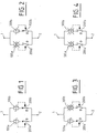
- the two varistors 100a and 100b are of preferably connected in parallel, respectively through thermal disconnectors 200a, 200b, between the lines to be protected 1, 2, as seen in figure 1.
- These lines 1 and 2 can correspond for example to a phase line and a neutral or earth line or still can correspond respectively to a neutral line and a earth line, for a single-phase network.
- Thermal disconnectors 200a and 200b are in contact thermal respectively with one of the two varistors 100a and 100b of so that the internal heating of the varistors 100a and 100b produced in end of life of these leads to the opening of the disconnectors.
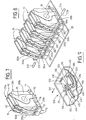
- Each protection cell 10 comprising two varistors 100a and 100b, as illustrated in FIG. 7, is preferably formed of two identical modules 50 each containing a varistor 100 as illustrated in Figures 5 and 6.
- each module 50 is preferably formed a support base 60 of electrically insulating material, a varistor 100, two connection blades 90 electrically conductors and a thermal disconnector 200.
- the support base 60 can be the subject of numerous modes of production. Preferably it is produced by molding a piece in plastic material.
- each support base 60 comprises a flat wall 62 and a sole 70.
- the wall 62 preferably has a contour generally trapezoidal. This wall 62 makes it possible to guarantee the electrical separation of the blades 90 of two adjacent modules 50 stacked as shown in the Figures 7 and 8 and therefore guarantee the electrical separation of varistors 100 stacked.
- the sole 70 is integral with the base of the wall 62, projecting laterally on it.
- the sole 70 preferably has the general shape of a parallelepiped block.
- the upper surface 71 of the sole 70 is preferably provided with several cradles 72, 73 adapted to receive varistors 100 of different geometries. So according to the embodiment shown in the accompanying figures, the upper surface 71 comprises a first central cradle 72 formed by a suitable cylindrical cap to receive a varistor 100 consisting of a contour disc cylindrical and a second cradle 73, which frames the first, suitable for receive a varistor 100 consisting of a general contour plate square with rounded corners.
- varistors 100 formed of discs or plates are attached to the wall 62, with their axis 101 perpendicular to this wall 62 and substantially centered on it.
- the support base 60 can be adapted for example to receive a choice of varistors rounds of 20 mm, 25 mm, 32 mm or 40 mm in diameter, varistors 34 mm square and this for all voltages between 275 V and 420 V.
- connection blades 90 are preferably identical. They are arranged respectively on either side of the varistor 100 associated and thus take it as a sandwich.
- Each module 50 thus comprises, depending on its thickness, successively: the wall 62, a first connecting blade 90, a varistor 100 and the second blade connection 90.
- each blade 90 is formed by cutting and stamping in a metal plate electrically driver. It includes a main body 91 plan which includes a central core 92 adapted to be fixed on a varistor electrode 100 and extended by two wings 94, 95 substantially diametrically opposite with respect to the axis 101 of the central core 92 and the varistor 100.
- the lower wing 95 is adapted to its free end opposite to the core 92, for an electrical connection, for example on a circuit printed.
- the upper wing 94 is preferably adapted to be fixed on the wall 62 in the vicinity of the upper edge thereof.
- This wing 94 can be fixed to the wall 62 for example using a rivet 93 or by bolting of a stud 98 molded on the wall 62 or by any equivalent means.
- This wing 94 is advantageously provided at its free end located on the outside of the varistor, of an extension 97 bent at 90 °, either perpendicular to the plane of the body 91.
- This extension 97 serves as connection point by welding to a blade 210 of the disconnector 200 as is will describe it later.
- the end of the wing 95 of one of the blades 90 can be housed in a complementary chamber 74 passing through the sole 70 in position adjacent to and parallel to the wall 62.
- Wing tip 95 of the other blade 90 can be housed in a complementary cavity 75 formed laterally in the sole 70.
- These ends of the wings 95 can be fixed on the sole 70 by any suitable means, for example using rivets 76 or bolting on the support base 60, or by any other means appropriate.
- the sole 70 is also preferably provided with lights 76, 77 perpendicular to the wall 62 designed to allow assembly between them several modules 50.
- Each disconnector 200 preferably comprises a blade 210 formed from an elastic, electrically conductive spring metal.
- the blade 210 is preferably generally flat at rest.
- a first end 212 of the blade 210 is fixed by welding 213 on the extension 97 of one of the connection blades 90 using of a low temperature fusible alloy. This blade 90 being in contact with the varistor 100, the solder 213 is placed at the temperature of this varistor 100. This solder 213 is suitable for melting when the Varistor 100 temperature exceeds a threshold at end of life.
- the blade 210 is placed laterally opposite the edge of the varistor 100 along a vertical edge of the wall 62. Thus the blade thermal disconnection 210 is located in the same plane as the varistor 100 which optimizes the overall dimensions of the assembly.
- the second end 214 of the blade 210 is fixed to the sole 70 by any appropriate means.
- this second end 214 of the blade 210 is engaged in a complementary channel 78 formed in the sole 70.
- the orientation of this channel 78 is adapted to impose a elastic deformation or bandage of the blade 210 as seen in the comparative examination of FIGS. 5 and 6, when the ends 212 and 214 of this blade 210 are respectively welded to the extension 97 and engaged in channel 78.
- the blade 210 is welded under stress and stressed by its intrinsic elasticity towards a position separating the extension 97 upon rupture of the weld 213.
- the disconnection blade 210 thus performs a quadruple function : a) in normal operation it is used for the electrical connection of the varistor 100, b) at the end of the life of a varistor 100 it is used to disconnect it, and c) guarantee compliance with the electrical insulation after disconnection and finally d) it is also used for training the visualization of varistor deficiency 100.
- the end 214 of the blade 210 is also adapted for a connection for example on a printed circuit.
- Cell 50 is connected between lines 1 and 2 by through the end 214 of the disconnect blade 210 and the end of the wing 95 of the connecting blade 90 opposite the blade of logout 210.
- These two modules 50 can for example be welded in position parallel on a printed circuit board.
- Each protection module 50 constitutes an element of autonomous and independent protection of the 400 case in which it is integrated.
- These display means 300 are adapted to inform a observer of the state of the two varistors 100 of each cell 10, in distinguishing the three cases illustrated in Figures 1 to 4 where respectively: a) the two varistors 100 are valid (figure 1), b) one of the two varistors 100 is out of service (figure 2 or 3) and although the protection is still assured it is desirable to change the protection cell, and c) the two varistors 100 are deficient (FIG. 4) in which case the protection is no longer ensured, it is necessary to change the protection.
- These display means 300 cooperate with the blade disconnection 210, more precisely the end 212 thereof.
- the display means 300 comprise, for each cell 10, a control cursor 310 and a display drawer 350.
- the slider 310 and the drawer 350 are preferably produced by molding of plastic parts.
- the drawer 350 is preferably at less partially formed of material of red color or provided with a at least partial coating of red color on an area of its surface moved next to a viewing window 410 produced in a case 400 of the device, as will be described later.
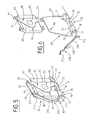
- case 400 is only partially shown. More specifically in Figure 9 there is shown a case 400 adapted to receive a protection cell 10 comprising two modules 50 and therefore two varistors 100. For a protection device for a three-phase network comprising four cells protection 10, the dimensions of the housing 400 must of course be adapted accordingly. Furthermore in the latter case, the case 400 is equipped with four separate display systems 300 associated respectively to each protection cell 10.
- Figures 9 to 13 show in particular two walls side 402 and 404 of the housing 400, orthogonal to one another and intended for be placed next to the section of the varistors 100. More precisely the wall 402 is placed opposite the disconnection blade 210, while the wall 404 is placed opposite the upper edge of the wall 62.
- the window 410 is preferably formed in the wall 404.
- the slider 310 and the drawer 350 are preferably guided translation, in respectively orthogonal directions, on the case 400.
- the case 400 is advantageously provided on its internal surface of structures molded to guide translation the cursor 310 and the drawer 350.
- FIG. 9 rectilinear ribs and parallel 420, 422 molded on the inner face of the wall 404 of the case 400 and adapted to guide the cursor 310 to translation in a direction 311 parallel to the mean plane of the varistors 100.
- a finger 430 molded protruding from the face internal of the wall 404 of the case and engaged in an oblong lumen 352 formed in the drawer 350 to guide the latter in translation in a direction 351 orthogonal to the aforementioned direction 311 and in the mean plane of the varistors 100.
- cursor 310 and the drawer 350 can be guided on the housing 400 by other functionally equivalent means.
- the control cursor 310 is adapted to be trained in displacement by the two disconnection blades 210 associated respectively to the two varistors 100a and 110b of the same cell protection.
- the cursor 310 is adapted to be moved of a first amplitude, in direction 311, when one any of these two disconnection blades 210 is moved into position opening after fusion of the corresponding weld 213, and be moved of a second amplitude, in the same direction 311, when the two disconnection blades 210 of cell 10 are in the open position.
- the cursor 310 preferably has symmetry with respect to to a plane parallel to direction 311 and which also corresponds to a plane of symmetry for the two varistors 100 of the same cell 10.
- the cursor 310 is formed of a bar central 312 provided on each side with the above-mentioned plane of symmetry of two drive finger stages 314 and 316.
- the fingers 314 of the first stage are relatively rigid. They are preferably perpendicular to the bar 312.
- the fingers 316 are on the contrary more flexible. They are trained preferably rectilinear elements inclined relative to the bar 312 and to the direction 311. Thus the fingers 316 typically form a "V" whose the point is directed towards the wall 402, ie towards the front with reference to the moving the cursor 310.
- the ends 212 of the two disconnection blades 210 of a same protection cell 10 are placed respectively between the fingers 314 and 316 of cursor 310.
- This double displacement of the cursor 310 is used to respectively view the degraded protection mode in which a only varistor remains active (figures 2 or 3) and the non-protection mode in which the two varistors 100 are inactive (FIG. 4).
- the slider 310 and the drawer 350 cooperate by through training structures 320, 370 inclined by relative to the directions of movement 311 and 351, for example at approximately 60 and 30 ° respectively from these two directions.
- the drive face 320 can be formed by one of the fingers 316.
- the drawer 350 is also stressed by an elastic structure 370 towards its original position shown in FIG. 10.
- this elastic structure 370 is formed by a curved blade coming from molding with the drawer 350 and which rests on a wall of the housing 400.
- a biasing blade coming from molding 370 may be replaced by any appropriate separate elastic structure attached to drawer 350 (for example a metal spiral spring, or a means equivalent).
- drawer 350 has structures 380 moved in window manhole 410, adapted to present a visual appearance different through this window, depending on the position of drawer 350.
- it can be structures 380 of geometry adapted to only partially cover the window 410 when the drawer 350 is moved to a first amplitude and to completely cover this window 410 when the drawer 350 is moved to the second amplitude.
- it may be a wall of the drawer 350 which completely covers window 410, but which has a different visual appearance (preferably a color) depending on the area of its surface placed opposite window 410.
- window 410 appears almost entirely 1) white or green when the two varistors 100a and 100b are in use and offer 100% protection, 2) partially in color red, when one of the two varistors 100 is out of service and the device is placed in shaded mode, and 3) completely in red color when the two varistors 100 are out of service.
- the protection device is further provided with means allowing remote sensing of the disconnection of at least one blades 210, in order to signal the deficiency of at least one of the varistors 100 and therefore the need to change the cell as soon as possible 10 or the corresponding module 50.
- Such remote sensing means can be the subject of different embodiments.
- these means include a flap 220 on each blade 210, associated with an optical detection barrier 230.
- Each flap 220 can be formed for example by bending at 90 ° a lug secured to the body of the blade 210, in a plane parallel to the medium shot of the varistors 100, on the outside of this body.
- the optical detection barrier 230 is formed by a transmitter optical 232 and an associated receiver 234, defining a barrier detection 230 parallel to the axes 101 of the varistors.
- This barrier 230 is located on the outside of the modules 10 near the flaps 220 so that during normal operation the optical barrier 230 is not obscured by any shutter 220, but that however this barrier 230 is interrupted by a shutter as soon as the corresponding disconnection blade 210 is moved to the open position after fusion of the weld 213 associated.
- This optical barrier 230 can be exploited by conventional means which will not be described below for operate a remote signaling.
- a display drawer 350 associated with a cursor 310 allows greater freedom in choosing the percentage of the window 410 covered in each viewing position that the use of the single cursor 310.
- a display device comprising only such a slider 310 in principle only allows percentages constant pitch overlap, typically 0%, 50% and 100%, the successive movements of the cursor 310 caused by the openings of the blades 210 being of identical amplitudes.
- the drawer visualization 350 could be deleted, the visualization of the state of the two varistors 100 of a cell 10 then being operated by displacement of the cursor 310 itself next to window 410.
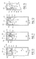
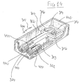
- FIGS 14 to 18 show a display device comprising a cursor 310 guided in translation in direction 311 against a wall 404 of the housing 400, opposite a window 410, formed in this wall 404.
- the cursor 310 again comprises a bar 312 provided with two rigid fingers 314 and two flexible fingers 316, as shown previously.
- the ends 212 of the two disconnection blades 210 of a same protection cell 10 are placed respectively between the fingers 314 and 316 of cursor 310.
- the first disconnection blade 210 activated moves the cursor 310 on a first amplitude, by solicitation of the associated finger 314. Simultaneously the opposite flexible finger 316 elastically crosses the second disconnection blade so that it ends up in look at the end of this flexible finger 316.
- this second disconnection blade 210 displaces then the cursor 310 on a second amplitude.
- the cursor 310 can be guided in the direction 311 by any suitable means, for example by a rib 405 secured to the wall 404.
- cursor 310 can be indexed in its translation, by an elastic beam 322 provided with a toothing 324 moved opposite an indexing surface having whose two notches 440, formed on the wall 404.
Landscapes
- Engineering & Computer Science (AREA)
- Microelectronics & Electronic Packaging (AREA)
- Physics & Mathematics (AREA)
- Electromagnetism (AREA)
- Thermistors And Varistors (AREA)
- Fuses (AREA)
- Emergency Protection Circuit Devices (AREA)
Abstract
Description
La présente invention concerne le domaine des dispositifs de protection des équipements électroniques et/ou électrotechniques à l'encontre de surtensions électriques transitoires.The present invention relates to the field of devices for protection of electronic and / or electrotechnical equipment to against transient electrical overvoltages.
Plus précisément la présente invention concerne le domaine des dispositifs de protection à base de varistances.More specifically, the present invention relates to the field protective devices based on varistors.
On a déjà proposé de nombreux dispositifs de protection à l'encontre de surtensions transitoires, comportant au moins une varistance.Numerous protective devices have already been proposed for against transient overvoltages, including at least one varistor.
En particulier la Demanderesse a proposé depuis de nombreuses années des dispositifs de protection comprenant deux varistances connectées en parallèle, entre des lignes à protéger, par l'intermédiaire de déconnecteurs à déclenchement thermique respectifs, sensibles au vieillissement de la varistance respectivement associée.In particular, the Applicant has proposed for many years of protection devices comprising two varistors connected in parallel, between lines to be protected, via respective thermal release disconnectors, sensitive to aging of the varistor respectively associated.
De tels dispositifs offrent l'avantage de maintenir une protection efficace, y compris lorsque l'une des deux varistances arrive en fin de vie, grâce à la présence de la seconde varistance.The advantage of such devices is that they maintain a effective protection, even when one of the two varistors arrives at the end of life, thanks to the presence of the second varistor.
La présente invention a cependant pour but de perfectionner les dispositifs de protection connus de ce type.The present invention however aims to improve known protective devices of this type.
Un but important de la présente invention est en particulier de proposer des moyens perfectionnés permettant de visualiser l'état des varistances formant le dispositif de protection.An important object of the present invention is in particular to to propose improved means making it possible to visualize the state of varistors forming the protection device.
Ces buts sont atteints selon la présente invention grâce à un dispositif de protection à l'encontre de surtensions transitoires, comprenant au moins deux varistances, des moyens de déconnexion sensibles à l'état de ces varistances et adaptés pour déconnecter individuellement chaque varistance en fin de vie de celle-ci et des moyens mécaniques de visualisation de l'état des varistances, reliés fonctionnellement aux moyens de déconnexion pour être actionnés par ceux-ci.These objects are achieved according to the present invention thanks to a protection device against transient overvoltages, comprising at least two varistors, disconnection means sensitive to the state of these varistors and adapted to disconnect individually each varistor at the end of its life and the means mechanical display of the state of the varistors, connected functionally to the disconnection means to be actuated by these.
Selon une autre caractéristique avantageuse de la présente invention, les moyens mécaniques de visualisation sont adaptés pour distinguer les cas où 1) les deux varistances sont en service, 2) l'une des deux varistances est déconnectée et 3) les deux varistances sont déconnectées.According to another advantageous characteristic of the present invention, the mechanical display means are suitable for distinguish the cases where 1) the two varistors are in service, 2) one of the two varistors is disconnected and 3) the two varistors are disconnected.
Selon une autre caractéristique avantageuse de la présente invention, les moyens mécaniques de visualisation comprennent un curseur actionné par les lames de déconnexion de deux varistances montées en parallèle, ledit curseur comprenant deux étages de doigts d'entrainement, les uns rigides, les autres flexibles pour franchir élastiquement une lame de déconnexion.According to another advantageous characteristic of the present invention, the mechanical display means comprise a cursor actuated by the disconnection blades of two varistors mounted in parallel, said cursor comprising two stages of fingers training, some rigid, others flexible to cross elastically a disconnection blade.
Selon une autre caractéristique avantageuse de la présente invention, les moyens mécaniques de visualisation comprennent en outre un tiroir de visualisation actionné par le curseur de commande.According to another advantageous characteristic of the present invention, the mechanical display means further comprise a display drawer activated by the control cursor.
Selon une autre caractéristique avantageuse de la présente invention, le dispositif comprend en outre des moyens de télésignalisation de la déconnexion de l'une au moins des varistances.According to another advantageous characteristic of the present invention, the device further comprises remote signaling means the disconnection of at least one of the varistors.
D'autres caractéristiques, buts et avantages de la présente invention apparaitront à la lecture de la description détaillée qui va suivre et en regard des dessins annexés donnés à titre d'exemple non limitatif et sur lesquels :
- la figure 1 représente le schéma électrique d'un dispositif de protection conforme à la présente invention,
- les figures 2 à 4 représentent le schéma électrique équivalent en cas de déficience de l'une ou des deux varistances,
- la figure 5 représente une vue en perspective d'un module de protection à une varistance, conforme à la présente invention,
- la figure 6 représente une vue en perspective éclatée du même module de protection à une varistance,
- la figure 7 représente un ensemble de deux modules de protection à une varistance appairés pour former une cellule de protection conforme à la présente invention,
- la figure 8 représente quatre cellules de protection conformes à la présente invention regroupées sur un support commun formé d'un circuit imprimé, pour la protection d'un réseau triphasé,
- la figure 9 représente une vue en perspective d'un dispositif mécanique de visualisation conforme à la présente invention,
- les figures 10, 11 et 12 représentent trois vues en plan de ce dispositif mécanique de visualisation à trois étapes successives de son fonctionnement,
- la figure 13 représente une autre vue du même dispositif mécanique de visualisation selon une vue orthogonale aux figures 10 à 12,
- la figure 14 représente une vue en perspective d'un dispositif mécanique de visualisation conforme à une variante de réalisation de la présente invention,
- la figure 15 représente une vue de détail du même dispositif, illustrant la coopération entre une lame de déconnexion et un curseur de visualisation, et
- les figures 16 à 18 représentent trois vues en plan de ce dispositif mécanique de visualisation à trois étapes successives de son fonctionnement.
- FIG. 1 represents the electrical diagram of a protection device in accordance with the present invention,
- Figures 2 to 4 show the equivalent electrical diagram in the event of a deficiency in one or both varistors,
- FIG. 5 represents a perspective view of a varistor protection module, in accordance with the present invention,
- FIG. 6 represents an exploded perspective view of the same protection module with a varistor,
- FIG. 7 represents a set of two protection modules with a varistor paired to form a protection cell according to the present invention,
- FIG. 8 represents four protection cells in accordance with the present invention grouped together on a common support formed by a printed circuit, for the protection of a three-phase network,
- FIG. 9 represents a perspective view of a mechanical display device according to the present invention,
- FIGS. 10, 11 and 12 represent three plan views of this mechanical display device at three successive stages of its operation,
- FIG. 13 represents another view of the same mechanical display device according to a view orthogonal to FIGS. 10 to 12,
- FIG. 14 represents a perspective view of a mechanical display device according to an alternative embodiment of the present invention,
- FIG. 15 represents a detailed view of the same device, illustrating the cooperation between a disconnection blade and a display cursor, and
- Figures 16 to 18 show three plan views of this mechanical display device in three successive stages of its operation.
Comme on l'a indiqué précédemment, le dispositif de protection
conforme à la présente invention comprend au moins deux varistances
100a, 100b, des moyens 200a, 200b de déconnexion sensibles à l'état de ces
varistances 100a, 100b et adaptés pour déconnecter individuellement
chaque varistance 100a, 100b en fin de vie de celle-ci et des moyens
mécaniques 300 de visualisation de l'état des varistances 100a, 100b, reliés
fonctionnellement aux moyens de déconnexion 200a, 200b pour être
actionnés par ceux-ci.As previously indicated, the protective device
according to the present invention comprises at least two
Plus précisément les deux varistances 100a et 100b sont de
préférence connectées en parallèle, respectivement par l'intermédiaire
de déconnecteurs thermiques 200a, 200b, entre les lignes à protéger 1, 2,
comme on le voit sur la figure 1. Ces lignes 1 et 2 peuvent correspondre
par exemple à une ligne de phase et une ligne de neutre ou de terre ou
encore peuvent correspondre respectivement à une ligne de neutre et une
ligne de terre, pour un réseau monophasé.More precisely, the two
Les déconnecteurs thermiques 200a et 200b sont en contact
thermique respectivement avec l'une des deux varistances 100a et 100b de
sorte que l'échauffement interne des varistances 100a et 100b produit en
fin de vie de celles-ci entraine l'ouverture des déconnecteurs.
Comme on le voit sur la figure 1, à l'origine, les deux varistances
100a et 100b sont en service et protègent les équipements raccordés aux
lignes 1 et 2. As seen in Figure 1, originally the two
Lorsque l'une des deux varistances 100a ou 100b arrive en fin de
vie, son échauffement provoque l'ouverture du déconnecteur 200a ou 200b
associé. Cependant les équipements restent protéger par l'autre varistance
100b ou 100a, comme on le voit sur la figure 2 ou la figure 3.When one of the two
En pratique les varistances réalisées de nos jours présentent des
dispersions suffisantes pour garantir que les deux varistances 100a et 100b
n'arrivent pas en fin de vie simultanément.In practice the varistors made today present
sufficient dispersions to ensure that the two
Enfin lorsque les deux varistances 100a et 100b arrivent en fin
de vie, celles-ci sont isolées toutes les deux des lignes 1 et 2, comme illustré
sur la figure 4.Finally when the two
Chaque cellule de protection 10 comprenant deux varistances
100a et 100b, comme illustrée sur la figure 7, est formée de préférence de
deux modules 50 identiques contenant chacun une varistance 100 comme
illustré sur les figures 5 et 6.Each
Plus précisément chaque module 50 est formé de préférence
d'une embase support 60 en matériau électriquement isolant, d'une
varistance 100, de deux lames de connexion 90 électriquement
conductrices et d'un déconnecteur thermique 200.More precisely, each
L'embase support 60 peut faire l'objet de nombreux modes de
réalisation. De préférence elle est réalisée par moulage d'une pièce en
matière plastique.The
Selon le mode de réalisation préférentiel représenté sur les
figures annexées chaque embase support 60 comprend une paroi plane 62
et une semelle 70.According to the preferred embodiment shown in the
attached figures each
La paroi 62 possède de préférence un contour généralement
trapézoïdal. Cette paroi 62 permet de garantir la séparation électrique des
lames 90 de deux modules 50 adjacents empilés comme représenté sur les
figures 7 et 8 et par conséquent de garantir la séparation électrique des
varistances 100 empilées.The
La semelle 70 est solidaire de la base de la paroi 62, en saillie
latéralement sur celle-ci. La semelle 70 a de préférence la forme générale
d'un bloc parallélépipédique.The sole 70 is integral with the base of the
La surface supérieure 71 de la semelle 70 est de préférence
munie de plusieurs berceaux 72, 73 adaptés pour recevoir des varistances
100 de différentes géométries. Ainsi selon le mode de réalisation
représenté sur les figures annexées, la surface supérieure 71 comprend
un premier berceau 72 central formé d'une calotte cylindrique adaptée
pour recevoir une varistance 100 constituée d'un disque de contour
cylindrique et un second berceau 73, qui encadre le premier, adapté pour
recevoir une varistance 100 constituée d'une plaquette de contour général
carré à angles arrondis.The
Ces varistances 100 formées de disques ou plaquettes sont
accolées à la paroi 62, avec leur axe 101 perpendiculaire à cette paroi 62 et
sensiblement centré sur celle-ci.These
Selon un mode de réalisation non limitatif, l'embase support 60
peut être adaptée par exemple pour recevoir au choix des varistances
rondes de 20 mm, 25 mm, 32 mm ou 40 mm de diamètre, des varistances
carrées de 34 mm de côté et ceci pour toutes les tensions comprises entre
275 V et 420 V.According to a nonlimiting embodiment, the
Les deux lames de connexion 90 sont de préférence identiques.
Elles sont disposées respectivement de part et d'autre de la varistance 100
associée et prennent ainsi celle-ci en sandwich. Chaque module 50
comprend ainsi selon son épaisseur successivement : la paroi 62, une
première lame de connexion 90, une varistance 100 et la seconde lame de
connexion 90.The two
De préférence selon le mode de réalisation préférentiel
représenté sur les figures annexées, chaque lame 90 est formée par
découpe et estampage dans une plaque de métal électriquement
conducteur. Elle comprend un corps principal 91 plan qui comporte une
âme centrale 92 adaptée pour être fixée sur une électrode de la varistance
100 et prolongée par deux ailes 94, 95 sensiblement diamétralement
opposées par rapport à l'axe 101 de l'âme central 92 et de la varistance 100.Preferably according to the preferred embodiment
shown in the accompanying figures, each
L'aile inférieure 95 est adaptée à son extrémité libre opposée à
l'âme 92, pour un raccordement électrique, par exemple sur un circuit
imprimé.The
L'aile supérieure 94 est de préférence adaptée pour être fixée
sur la paroi 62 au voisinage du bord supérieur de celui-ci. Cette aile 94 peut
être fixée sur la paroi 62 par exemple à l'aide d'un rivet 93 ou par
bouterrolage d'un téton 98 venu de moulage sur la paroi 62 ou encore par
tout moyen équivalent. The
Cette aile 94 est avantageusement munie à son extrémité libre
située sur l'extérieur de la varistance, d'un prolongement 97 plié à 90°,
soit perpendiculairement au plan du corps 91. Ce prolongement 97 sert de
point de liaison par soudure à une lame 210 du déconnecteur 200 comme on
le décrira par la suite.This
L'extrémité de l'aile 95 de l'une des lames 90 peut être logée dans
une chambre complémentaire 74 traversant la semelle 70 en position
adjacente à la paroi 62 et parallèlement à celle-ci. L'extrémité de l'aile 95
de l'autre lame 90 peut être logée dans une cavité 75 complémentaire
formée latéralement dans la semelle 70.The end of the
Ces extrémités des ailes 95 peuvent être fixées sur la semelle 70
par tout moyen approprié, par exemple à l'aide de rivets 76 ou
bouterrolage sur l'embase support 60, ou encore par tout moyen
approprié.These ends of the
La semelle 70 est également munie de préférence de lumières 76,
77 perpendiculaires à la paroi 62 conçues pour permettre d'assembler
entre eux plusieurs modules 50.The sole 70 is also preferably provided with
Chaque déconnecteur 200 comprend de préférence une lame 210
formée en un métal ressort élastique et électriquement conducteur. La
lame 210 est de préférence généralement plane au repos.Each
Une première extrémité 212 de la lame 210 est fixée par soudure
213 sur le prolongement 97 de l'une des lames de connexion 90 à l'aide
d'un alliage fusible à basse température. Cette lame 90 étant en contact
avec la varistance 100, la soudure 213 est placée à la température de cette
varistance 100. Cette soudure 213 est adaptée pour fondre lorsque la
température de la varistance 100 dépasse un seuil en fin de vie.A
La lame 210 est placée latéralement en regard de la tranche de la
varistance 100 le long d'un bord vertical de la paroi 62. Ainsi la lame de
déconnexion thermique 210 est située dans le même plan que la varistance
100 ce qui permet d'optimiser l'encombrement de l'ensemble.The
La seconde extrémité 214 de la lame 210 est fixée sur la semelle
70 par tout moyen approprié. De préférence cette seconde extrémité 214 de
la lame 210 est engagée dans un canal complémentaire 78 formé dans la
semelle 70. L'orientation de ce canal 78 est adaptée pour imposer une
déformation élastique ou bandage de la lame 210 comme on le voit à
l'examen comparé des figures 5 et 6, lorsque les extrémités 212 et 214 de
cette lame 210 sont respectivement soudées sur le prolongement 97 et
engagée dans le canal 78.The
Ainsi la lame 210 est soudée en contrainte et sollicitée par son
élasticité intrinsèque vers une position de séparation du prolongement 97
dès rupture de la soudure 213.Thus the
Quand la varistance 100 arrive en fin de vie elle s'échauffe
progressivement et fait fondre l'alliage fusible 213. La lame de
déconnexion 210 est ainsi libérée et grâce à son élasticité, s'éloigne de la
lame 90 associée.When the
La lame de déconnexion 210 assure ainsi une quadruple fonction
: a) en fonctionnement normal elle sert à la liaison électrique de la
varistance 100, b) en fin de vie d'une varistance 100 elle sert à
déconnecter celle-ci, et c) à garantir le respect de l'isolement électrique
après déconnexion et enfin d) elle sert également à l'entrainement de la
visualisation de la déficience de la varistance 100.The
L'extrémité 214 de la lame 210 est également adaptée pour un
raccordement par exemple sur un circuit imprimé.The
La cellule 50 est raccordée entre les lignes 1 et 2 par
l'intermédiaire de l'extrémité 214 de la lame de déconnexion 210 et de
l'extrémité de l'aile 95 de la lame de connexion 90 opposée à la lame de
déconnexion 210.
Pour appairer deux modules 50 afin de former une cellule 10 il
suffit de fixer entre elles les semelles 70 de deux modules adjacents comme
illustré sur la figure 7.To pair two
Ces deux modules 50 peuvent par exemple être soudés en position
parallèle sur un circuit imprimé de raccordement.These two
Bien entendu les deux lames de déconnexion 210 associées
respectivement aux varistances 100 d'une même cellule 10 sont
indépendantes entre elles.Of course the two
Comme on l'a représenté sur la figure 8, pour la protection d'un
réseau triphasé, on peut ainsi disposer quatre cellules 10 comprenant
chacune deux modules 50, sur un circuit imprimé commun 20. Les
différentes varistances 100 ont leurs axes respectifs 101 coaxiaux.As shown in Figure 8, for the protection of a
three-phase network, it is thus possible to have four
Chaque module de protection 50 constitue un élément de
protection autonome et indépendant du boitier 400 dans lequel il est
intégré.Each
On va maintenant décrire la structure des moyens de
visualisation 300 représenté sur les figures 9 à 13.We will now describe the structure of the means of
Ces moyens de visualisation 300 sont adaptés pour informer un
observateur de l'état des deux varistances 100 de chaque cellule 10, en
distinguant les trois cas illustrés sur les figures 1 à 4 où respectivement :
a) les deux varistances 100 sont valides (figure 1), b) l'une des deux
varistances 100 est hors service (figure 2 ou 3) et bien que la protection
soit encore assurée il est souhaitable de changer la cellule de protection, et
c) les deux varistances 100 sont déficientes (figure 4) auquel cas la
protection n'étant plus assurée, il est nécessaire de changer la cellule de
protection.These display means 300 are adapted to inform a
observer of the state of the two
Ces moyens de visualisation 300 coopèrent avec la lame de
déconnexion 210, plus précisément l'extrémité 212 de celle-ci.These display means 300 cooperate with the
Selon le mode de réalisation préférentiel représenté sur les
figures 9 à 13, les moyens de visualisation 300 comprennent, pour chaque
cellule 10, un curseur de commande 310 et un tiroir de visualisation 350.According to the preferred embodiment shown in the
Figures 9 to 13, the display means 300 comprise, for each
Le curseur 310 et le tiroir 350 sont realisés de préférence par
moulage de pièces en matière plastique. Le tiroir 350 est de préférence au
moins partiellement formé de matière de couleur rouge ou muni d'un
revêtement au moins partiel de couleur rouge sur une zone de sa surface
déplacée en regard d'une fenêtre de visualisation 410 réalisée dans un
boitier 400 du dispositif, comme on va le décrire par la suite.The
Sur les figures annexées le boitier 400 est seulement
partiellement représenté. Plus précisément sur la figure 9 on a représenté
un boitier 400 adapté pour recevoir une cellule de protection 10
comprenant deux modules 50 et donc deux varistances 100. Pour un
dispositif de protection d'un réseau triphasé comprenant quatre cellules
de protection 10, les dimensions du boitier 400 doivent bien entendu être
adaptées en conséquence. Par ailleurs dans ce dernier cas, le boitier 400
est muni de quatre systèmes de visualisation 300 distincts associés
respectivement à chaque cellule de protection 10.In the appended figures the
Sur les figures 9 à 13 on a représenté notamment deux parois
latérales 402 et 404 du boitier 400, orthogonales entre elles et destinées à
être placées en regard de la tranche des varistances 100. Plus précisément
la paroi 402 est placée en regard de la lame de déconnexion 210, tandis que
la paroi 404 est placée en regard du bord supérieur de la paroi 62.Figures 9 to 13 show in particular two
La fenêtre 410 est de préférence formée dans la paroi 404.The
Le curseur 310 et le tiroir 350 sont de préférence guidés à
translation, dans des directions respectivement orthogonales, sur le
boitier 400. A cette fin le boitier 400 est muni avantageusement sur sa
surface interne de structures venues de moulage permettant de guider à
translation le curseur 310 et le tiroir 350.The
On aperçoit ainsi sur la figure 9 des nervures rectilignes et
parallèles 420, 422 venues de moulage sur la face interne de la paroi 404 du
boitier 400 et adaptées pour guider le curseur 310 à translation dans une
direction 311 parallèle au plan moyen des varistances 100. De même on
aperçoit sur la figure 9 un doigt 430 venu de moulage en saillie sur la face
interne de la paroi 404 du boitier et engagée dans une lumière oblongue
352 formée dans le tiroir 350 pour guider celui-ci à translation dans une
direction 351 orthogonale à la direction 311 précitée et au plan moyen des
varistances 100.We thus see in FIG. 9 rectilinear ribs and
parallel 420, 422 molded on the inner face of the
Bien entendu le curseur 310 et le tiroir 350 peuvent être guidés
sur le boitier 400 par d'autres moyens fonctionnellement équivalents.Of course the
Le curseur de commande 310 est adapté pour être entrainé en
déplacement par les deux lames de déconnexion 210 associées
respectivement aux deux varistances 100a et 110b d'une même cellule de
protection.The
Plus précisément le curseur 310 est adapté pour être déplacé
d'une première amplitude, selon la direction 311, lorsque l'une
quelconque de ces deux lames de déconnexion 210 est déplacée en position
d'ouverture aprés fusion de la soudure correspondante 213, et être déplacé
d'une seconde amplitude, dans la même direction 311, lorsque les deux
lames de déconnexion 210 de la cellule 10 sont en position d'ouverture.More precisely the
Le curseur 310 possède de préférence une symétrie par rapport
à un plan parallèle à la direction 311 et qui correspond également à un
plan de symétrie pour les deux varistances 100 d'une même cellule 10.The
Selon le mode de réalisation particulier et non limitatif
représenté sur les figures 9 à 13, le curseur 310 est formé d'un barreau
central 312 pourvu de chaque côté du plan de symétrie précité de deux
étages de doigt d'entrainement 314 et 316. Les doigts 314 du premier étage
sont relativement rigides. Ils sont de préférence perpendiculaires au
barreau 312. Les doigts 316 sont au contraire plus souples. Ils sont formés
de préférence d'éléments rectilignes inclinés par rapport au barreau 312
et à la direction 311. Ainsi les doigts 316 forment typiquement un "V" dont
la pointe est dirigée vers la paroi 402, soit vers l'avant en référence au
déplacement du curseur 310.According to the particular and nonlimiting embodiment
shown in Figures 9 to 13, the
Les extrémités 212 des deux lames de déconnexion 210 d'une
même cellule de protection 10 sont placées respectivement entre les doigts
314 et 316 du curseur 310.The ends 212 of the two
Ainsi lorsque l'une des lames de déconnexion 210 est libérée par
fusion de la soudure 213 correspondante, elle déplace le curseur 310 à
translation sur une première amplitude, en rapprochement de la paroi
402, par sollicitation de l'un des doigts 314 du premier étage, comme on le
voit à l'examen comparé des figures 10 et 11. Au cours de ce processus le
doigt 316 du second étage situé de l'autre côté du plan de symétrie du
curseur 310 franchit élastiquement l'extrémité de la seconde lame de
déconnexion 210, comme on le voit également à l'examen comparé des
figures 10 et 11.So when one of the
De ce fait lorsque la seconde lame de déconnexion 210 est libérée
à son tour par fusion de la soudure 213 correspondant, elle déplace à
nouveau le curseur 310 à translation sur une seconde amplitude, en
rapprochement de la paroi 402, par sollicitation du doigt 316 précité du
second étage, comme on le voit à l'examen comparé des figures 11 et 12.Therefore when the
Ce double déplacement du curseur 310 est exploité pour
visualiser respectivement le mode dégradé de protection dans lequel une
seule varistance reste active (figures 2 ou 3) et le mode hors protection
dans lequel les deux varistances 100 sont inactives (figure 4).This double displacement of the
Pour celà le curseur 310 et le tiroir 350 coopèrent par
l'intermédiaire de structures d'entrainement 320, 370 inclinées par
rapport aux directions de déplacement 311 et 351, par exemple à environ
60 et 30° respectivement de ces deux directions.For this, the
Sur le curseur 310 la face d'entrainement 320 peut être formée
par l'un des doigts 316. On the
L'homme de l'art comprendra aisément à l'examen des figures
10 à 12 que le déplacemnet en deux temps du curseur 310 dans la direction
311 permet de déplacer de même en deux temps le tiroir de visualisation
350 dans la direction 351, en regard de la fenêtre 410.Those skilled in the art will readily understand on examining the figures
10 to 12 move the
Le tiroir 350 est par ailleurs sollicité par une structure élastique
370 vers sa position d'origine représentée sur la figure 10. Selon le mode
de réalisation préférentiel représenté sur les figures annexées, cette
structure élastique 370 est formée d'une lame incurvée venue de moulage
avec le tiroir 350 et qui repose sur une paroi du boitier 400. En variante
cependant une telle lame de sollicitation venue de moulage 370 pourra être
remplacée par toute structure élastique distincte appropriée rapportée sur
le tiroir 350 (par exemple un ressort spiral en métal, ou un moyen
équivalent).The
Par ailleurs le tiroir 350 possède des structures 380 déplacées en
regard de la fenêtre 410, adaptées pour présenter un aspect visuel
différent à travers cette fenêtre, en fonction de la position du tiroir 350.Furthermore the
Comme on le voit sur les figures 10 à 12, il peut s'agir de
stuctures 380 de géométrie adaptée pour ne recouvrir que partiellement la
fenêtre 410 lorsque le tiroir 350 est déplacé sur une première amplitude et
pour recouvrir totalement cette fenêtre 410 lorsque le tiroir 350 est
déplacé sur la seconde amplitude. En variante il peut s'agir d'une paroi du
tiroir 350 qui recouvre totalement en permanence la fenêtre 410, mais qui
présente un aspect visuel (de préférence une couleur) différent selon la
zone de sa surface placée en regard de la fenêtre 410.As seen in Figures 10 to 12, it can be
Ainsi de préférence la fenêtre 410 apparait quasi intégralement
1) de couleur blanche ou verte lorsque les deux varistances 100a et 100b
sont en service et offrent 100% de protection, 2) partiellement en couleur
rouge, lorsque l'une des deux varistances 100 est hors service et le
dispositif est placé en mode dégragé, et 3) totalement en couleur rouge
lorsque les deux varistances 100 sont hors service.So preferably
Ainsi l'utilisateur est averti de l'usure du dispositif de protection
par mise hors service d'une varistance 100, avant sa destruction totale et
donc avant l'absence totale de protection.Thus the user is warned of the wear of the protection device
by decommissioning a
Selon l'invention le dispositif de protection est muni en outre de
moyens permettant une télédétection de la déconnexion de l'une au moins
des lames 210, afin de signaler la déficience de l'une au moins des
varistances 100 et donc la nécessité de changer dés que possible la cellule
10 ou le module 50 correspondant.According to the invention the protection device is further provided with
means allowing remote sensing of the disconnection of at least one
De tels moyens de télédétection peuvent faire l'objet de différents modes de réalisation.Such remote sensing means can be the subject of different embodiments.
Selon le mode de réalisation préférentiel représenté sur les
figures 6 et 8 annexées ces moyens comprennent un volet 220 sur chaque
lame 210, associé à une barrière optique de détection 230.According to the preferred embodiment shown in the
Figures 6 and 8 attached these means include a
Chaque volet 220 peut être formé par exemple par pliage à 90°
d'une patte solidaire du corps de la lame 210, dans un plan parallèle au
plan moyen des varistances 100, sur l'extérieur de ce corps.Each
La barrière optique de détection 230 est formée par un émetteur
optique 232 et un récepteur 234 associé, définissant une barrière de
détection 230 parallèle aux axes 101 des varistances. Cette barrière 230 est
située sur l'extérieur des modules 10 à proximité des volets 220 de sorte que
en fonctionnement normal la barrière optique 230 ne soit pas occultée par
un volet 220 quelconque, mais que cependant cette barrière 230 soit
interrompue par un volet dès que la lame de déconnexion correspondant
210 est déplacée en position d'ouverture après fusion de la soudure 213
associée.The
La rupture de cette barrière optique 230 peut être exploitée par
des moyens conventionnels qui ne seront pas décrits par la suite pour
opérer une télésignalisation.The rupture of this
L'utilisation d'un tiroir de visualisation 350 associé à un curseur
310, permet une plus grande liberté dans le choix du pourcentage de la
fenêtre 410 recouverte dans chaque position de visualisation que
l'utilisation du seul curseur 310. Un dispositif de visualisation comprenant
seulement un tel curseur 310 ne permet en principe que des pourcentages
de recouvrement de pas constant, typiquement 0%, 50% et 100%, les
déplacements successifs du curseur 310 provoqués par les ouvertures des
lames 210 étant d'amplitudes identiques.The use of a
Bien entendu la présente invention n'est pas limitée aux modes de réalisation particuliers qui viennent d'être décrits mais s'étend à toutes variantes conformes à son esprit.Of course, the present invention is not limited to the modes of particular embodiments which have just been described but extends to all variants according to his spirit.
Ainsi par exemple selon une variante de réalisation, le tiroir de
visualisation 350 pourrait être supprimé, la visualisation de l'état des deux
varistances 100 d'une cellule 10 étant alors opérée par déplacement du
curseur 310 lui même en regard de la fenêtre 410.Thus for example according to an alternative embodiment, the
On va maintenant décrire la variante de réalisation des moyens de visualisation illustrés sur les figures 14 à 18.We will now describe the variant embodiment of the means display illustrated in Figures 14 to 18.
On retrouve sur ces figures 14 à 18 un dispositif de visualisation
comprenant un curseur 310 guidé à translation dans la direction 311
contre une paroi 404 du boítier 400, en regard d'une fenêtre 410, formée
dans cette paroi 404.These figures 14 to 18 show a display device
comprising a
Le curseur 310 comprend là encore un barreau 312 muni de
deux doigts rigides 314 et deux doigts souples 316, comme indiqué
précédemment.The
De même, comme indiqué en regard des figures 10 à 13, à
l'origine, les extrémités 212 des deux lames de déconnexion 210 d'une
même cellule de protection 10 sont placées respectivement entre les doigts
314 et 316 du curseur 310.Similarly, as indicated with reference to FIGS. 10 to 13, at
the origin, the
La première lame de déconnexion 210 activée déplace le curseur
310 sur une première amplitude, par sollicitation du doigt associé 314.
Simultanément le doigt souple 316 opposé franchit élastiquement la
seconde lame de déconnexion de sorte que celle-ci se retrouve alors en
regard de l'extrémité de ce doigt souple 316.The
L'activation de cette seconde lame de déconnexion 210 déplace
alors le curseur 310 sur une seconde amplitude.Activation of this
Ces déplacements sont visualisés par une couverture différente
de la fenêtre 410, par le curseur 310, plus précisément une aile 313
solidaire du barreau 312.These movements are visualized by a different cover
of
Le curseur 310 peut être guidé dans la direction 311 par tout
moyen approprié, par exemple par une nervure 405 solidaire de la paroi
404.The
Comme on le voit sur les figures 14 à 18, le curseur 310 peut être
indexé dans sa translation, par une poutre élastique 322 munie d'une
denture 324 déplacée en regard d'une surface d'indexation possédant dont
deux crans 440, formée sur la paroi 404.As seen in Figures 14-18,
Claims (29)
- A device for providing protection against transient electrical surges, the device comprising at least two varistors (100a. 100b), disconnection means (200a, 200b) responsive to the states of the varistors (100a, 100b) and adapted to disconnect each varistor individually at the end of its lifetime, and mechanical means (300) for displaying the states of the varistors (100a, 100b), and functionally connected to the disconnection means (200) to be actuated thereby.
- A device according to claim 1, characterized by the fact that the mechanical display means (300) are adapted to distinguish between the following cases: 1) both varistors (100a. 100b) are in operation; 2) one of the two varistors (100a, 100b) is disconnected: and 3) both varistors (100a. 100b) are disconnected.
- A device according to claim 1 or 2, characterized by the fact that the mechanical display means (300) comprise a traveller (310) actuated by the disconnection blades (210) of two varistors (100a, 100b) connected in parallel, said traveller (310) having two stages of drive fingers (214, 216) the fingers of one stage (214) being rigid and the fingers of the other stage (216) being flexible to go elastically past a disconnection blade (210).
- A device according to any one of claims 1 to 3, characterized by the fact that the mechanical display means (300) further comprise a display slide (350) actuated by the control traveller (310).
- A device according to any one of claims 1 to 4, characterized by the fact that it further comprises means (232, 234, 220) for remotely signalling disconnection of at least one of the varistors (100).
- A device according to any one of claims 1 to 5, characterized by the fact that each protection cell (10) comprising two varistors (100a and 100b) is made up of two identical modules (50).
- A device according to claim 6, characterized by the fact that each module (50) is formed by a supporting base (60) of electrically insulating material. a varistor (100), two electrically conductive connection blades (90), and a thermal disconnector (200).
- A device according to claim 7, characterized by the fact that each supporting base (60) comprises a plane wall (62) enabling two adjacent varistors (100) to be isolated, and a sole plate (70) serving as a support cradle for a varistor (100).
- A device according to claim 8. characterized by the fact that the top surface (71) of the sole plate (70) is provided with a plurality of cradles (72. 73) adapted to receive varistors (100) of different shapes.
- A device according to claim 9, characterized by the fact that the top surface (71) of the sole plate (70) comprises a central first cradle (72) constituted by a portion of a cylindrical surface adapted to receive a varistor (100) constituted by a disk of cylindrical outline, and a second cradle (73) on either side of the first and adapted to receive a varistor (100) constituted by a slab of generally square outline with rounded corners.
- A device according to any one of claims 1 to 10, characterized by the fact that the two connection blades (90) associated with a varistor (100) are identical.
- A device according to any one of claims 1 to 11, characterized by the fact that each module (50) comprises the following in succession in its thickness direction: an electrically insulating wall (62), a first connection blade (90), a varistor (100). and a second connection blade (90).
- A device according to any one of claims 1 to 12, characterized by the fact that each connection blade (90) comprises a plane main body (91) which includes a central core (92) adapted to be fixed on an electrode of the varistor (100) and extended by two arms (94, 95) that are substantially diametrically opposite about the axis (101) of the central core (92) and of the varistor (100).
- A device according to any one of claims 1 to 13, characterized by the fact that each thermal disconnector (200) comprises a blade (210) formed by electrically conductive resilient spring metal bonded under mechanical stress to a connection blade (90) connected to the varistor (100).
- A device according to claim 14, characterized by the fact that a first end (212) of the disconnection blade (210) is fixed by solder (213) to an extension (97) of one of the connection blades (90) using a low melting temperature alloy, while its second end (214) is fixed on a sole plate (70) of a supporting base (60).
- A device according to any one of claims 1 to 15, characterized by the fact that the disconnection blade (210) is located laterally facing an edge of the varistor (100).
- A device according to any one of claims 1 to 16, characterized by the fact that the disconnection blade (210) perform four functions: a) in normal operation it serves to provide electrical connection of the varistor (100): b) at the end of the lifetime of a varistor (100) it serves to disconnect it: c) after disconnection it guarantees electrical isolation; and d) it also serves to drive the display indicating that the varistor (100) has failed.
- A device according to claim 4, characterized by the fact that the traveller (310) and the slide (350) are guided in translation in mutually orthogonal directions on a housing (400).
- A device according to any one of claims 1 to 18, characterized by the fact that it includes a traveller (310) adapted to be displaced through a first amplitude in a particular direction (311) when either of the two disconnection blades (210) is displaced into its open position after the corresponding solder (213) has melted, and to be displaced through a second amplitude, in the same direction (311), when both disconnection blades (210) of the cell (10) are in the open position.
- A device according to claim 19, characterized by the fact that the traveller (310) is symmetrical about a plane parallel to the translation direction (311).
- A device according to claim 19 or 20. characterized by the fact that the traveller (310) is formed by a central bar (312) provided on either side of a plane of symmetry with two stages of drive fingers (314 and 316). the fingers in one of the stages (314) being relatively rigid and perpendicular to the bar (312), and the fingers of the other stage (316) being flexible. constituting rectilinear elements that are inclined relative to the bar (312) and to the translation direction (311).
- A device according to claim 21, characterized by the fact that the ends (212) of the two connection blades (210) of the same protection cell (10) are placed between respective sets of fingers (314 and 316) of the traveller (310).
- A device according to claim 4 or 18. characterized by the fact that the traveller (310) and the slide (350) co-operate via drive structures (320. 370) inclined relative to the respective displacement directions (311 and 351) thereof. e.g. at about 60° to 30° to said two directions.
- A device according to any one of claims 1 to 23, taken in combination with claim 3 or 4, characterized by the fact that the slide (350) and/or the traveller (310) is urged by a resilient structure (370) towards its original position.
- A device according to claim 24, characterized by the fact that the resilient structure (370) is formed by a curved blade integrally molded with the slide (350) or the traveller (310) and which rests against a wall of the housing (400).
- A device according to claim 24 or 25, characterized by the fact that the slide (350) or the traveller (310) possesses structures (380) that are moved past a window (410) formed in the housing (400) and adapted to present different visual appearance through said window as a function of the position of the slide (350) or of the traveller (310).
- A device according to claim 5. characterized by the fact that the remote signalling means comprise a flap (220) on each disconnection blade (210) associated with an optical detection barrier (230).
- A device according to any one of claims 1 to 27, characterized by the fact that it comprises at least three cells (10) each comprising two modules (50) each possessing one varistor (100) to protect a three phase network.
- A device according to any one of claims 1 to 28, characterized by the fact that it includes means (322. 324; 440) for indexing a traveller (310).
Applications Claiming Priority (2)
| Application Number | Priority Date | Filing Date | Title |
|---|---|---|---|
| FR9414586A FR2727806A1 (en) | 1994-12-05 | 1994-12-05 | PROTECTION DEVICE AGAINST TRANSIENT OVERVOLTAGES BASED ON VARISTORS AND THERMAL DISCONNECTORS |
| FR9414586 | 1994-12-05 |
Publications (2)
| Publication Number | Publication Date |
|---|---|
| EP0716493A1 EP0716493A1 (en) | 1996-06-12 |
| EP0716493B1 true EP0716493B1 (en) | 1998-07-29 |
Family
ID=9469473
Family Applications (1)
| Application Number | Title | Priority Date | Filing Date |
|---|---|---|---|
| EP95402729A Expired - Lifetime EP0716493B1 (en) | 1994-12-05 | 1995-12-04 | Transient overvoltage protection device with varistors and thermal disconnectors |
Country Status (4)
| Country | Link |
|---|---|
| EP (1) | EP0716493B1 (en) |
| AT (1) | ATE169155T1 (en) |
| DE (1) | DE69503743T2 (en) |
| FR (1) | FR2727806A1 (en) |
Cited By (9)
| Publication number | Priority date | Publication date | Assignee | Title |
|---|---|---|---|---|
| US7483252B2 (en) | 2006-12-05 | 2009-01-27 | Ferraz Shawmut S.A. | Circuit protection device |
| DE102008026555A1 (en) | 2008-06-03 | 2009-12-10 | Dehn + Söhne Gmbh + Co. Kg | Overvoltage protection device with thermal cut-off device |
| DE102008048644A1 (en) | 2008-08-01 | 2010-02-04 | Dehn + Söhne Gmbh + Co. Kg | Overvoltage protection device with one or more parallel-connected, located in a structural unit overvoltage limiting elements |
| USRE42319E1 (en) | 1998-06-08 | 2011-05-03 | Mersen France Sb Sas | Circuit protection device |
| US8179652B2 (en) | 2008-06-24 | 2012-05-15 | Phoenix Contact Gmbh & Co. Kg | Overvoltage protection element |
| US8477468B2 (en) | 2011-11-04 | 2013-07-02 | Mersen Usa Newburyport-Ma, Llc | Circuit protection device |
| US8482896B2 (en) | 2009-06-25 | 2013-07-09 | Phoenix Contact Gmbh & Co. Kg | Overvoltage protection element |
| US8810988B2 (en) | 2011-11-04 | 2014-08-19 | Mersen Usa Newburyport-Ma, Llc | Circuit protection device |
| US11152769B2 (en) * | 2018-02-27 | 2021-10-19 | Dehn Se + Co Kg | Overvoltage protection arrangement consisting of a horn spark gap accommodated in an insulating housing |
Families Citing this family (42)
| Publication number | Priority date | Publication date | Assignee | Title |
|---|---|---|---|---|
| US5959822A (en) * | 1995-12-22 | 1999-09-28 | Hubbell Incorporated | Compact lightning arrester assembly |
| FR2756673B1 (en) * | 1996-11-29 | 2003-05-30 | Soule Materiel Electr | PROTECTION DEVICE FOR TELEPHONE LINES |
| FR2783365B1 (en) * | 1998-09-15 | 2000-12-01 | Soule Materiel Electr | DEVICE FOR PROTECTING ELECTRICAL INSTALLATIONS AGAINST INTERFERENCE WITH THE POWER SUPPLY |
| FR2783362B1 (en) * | 1998-09-15 | 2000-12-01 | Soule Materiel Electr | ELECTRICAL NETWORK MANAGEMENT ASSEMBLY INCLUDING IMPROVED CONNECTION MEANS |
| CZ300555B6 (en) * | 2002-03-11 | 2009-06-17 | Kiwa, Spol. S R.O. | Overvoltage protection device |
| DE102004024657B4 (en) * | 2004-04-02 | 2006-12-21 | Dehn + Söhne Gmbh + Co. Kg | Arrangement for dissipating overvoltages with parallel-connected overvoltage-limiting elements in a structural unit |
| CN100539342C (en) * | 2004-04-02 | 2009-09-09 | 德恩及索恩两合股份有限公司 | Overvoltage side-discharging device |
| FR2869155B1 (en) * | 2004-04-19 | 2006-06-02 | Soule Prot Surtensions Sa | OVERVOLTAGE PROTECTION DEVICE WITH IMPROVED VISUALIZATION SYSTEM |
| US7477503B2 (en) * | 2005-04-30 | 2009-01-13 | Efi Electronics Corporation | Circuit protection device |
| DE102006042028B3 (en) * | 2006-07-19 | 2007-09-27 | Dehn + Söhne Gmbh + Co. Kg | Separation device for pluggable surge arrester, has metallic form part and finger standing under self-spring stress, where finger is supported at guide and is engaged into space closed by u-shaped end of metallic form part |
| DE102007006617B3 (en) * | 2007-02-06 | 2008-09-04 | Phoenix Contact Gmbh & Co. Kg | Overvoltage protection element has housing, with two overvoltage-limiting component arranged in housing, where control rod is shifted to distance, even if slide valve is passed from position to another position |
| DE102007024622B4 (en) | 2007-04-24 | 2017-02-23 | Phoenix Contact Gmbh & Co. Kg | Overvoltage protection device |
| DE102007042991B4 (en) | 2007-06-11 | 2009-09-17 | Dehn + Söhne Gmbh + Co. Kg | Surge protection device with mechanical disconnection device activated in thermal overload |
| DE102007030653B4 (en) | 2007-07-02 | 2017-04-13 | Phoenix Contact Gmbh & Co. Kg | Snubber |
| DE102008031917B4 (en) | 2008-07-08 | 2017-06-22 | Phoenix Contact Gmbh & Co. Kg | Snubber |
| DE102008047396B3 (en) | 2008-08-22 | 2010-03-11 | Dehn + Söhne Gmbh + Co. Kg | Overvoltage protection device with thermal cut-off device |
| DE102008061323B3 (en) | 2008-12-11 | 2010-06-24 | Phoenix Contact Gmbh & Co. Kg | Excess voltage protection unit has a varistor which, on a thermal overload, shifts for separation from the contacts |
| FR2948490A1 (en) | 2009-07-21 | 2011-01-28 | Abb France | DEVICE FOR PROTECTING AN ELECTRICAL INSTALLATION AGAINST TRANSIENT OVERVOLTAGES |
| DE102009035060A1 (en) * | 2009-07-28 | 2011-02-03 | Phoenix Contact Gmbh & Co. Kg | Snubber |
| DE102009036125A1 (en) | 2009-08-05 | 2011-02-10 | Phoenix Contact Gmbh & Co. Kg | Snubber |
| CZ308826B6 (en) * | 2009-10-19 | 2021-06-23 | KIWA sk, s.r.o | Surge protection equipment |
| DE202010014430U1 (en) | 2009-11-05 | 2011-03-24 | Phoenix Contact Gmbh & Co. Kg | Overvoltage protection element and electrical device |
| DE102009053145A1 (en) | 2009-11-05 | 2011-05-12 | Phoenix Contact Gmbh & Co. Kg | Overvoltage protection device, has thermal expandable material arranged within housing such that pole of varistor does not stay in electrically conductive contact with connection elements |
| FR2958789B1 (en) | 2010-04-09 | 2012-05-11 | Abb France | DEVICE FOR PROTECTION AGAINST TRANSIENT OVERVOLTAGES WITH IMPROVED THERMAL DISCONNECTOR |
| FR2958787B1 (en) * | 2010-04-09 | 2012-05-11 | Abb France | DEVICE FOR PROTECTION AGAINST OVERVOLTAGES WITH DEDUCTIVE THERMAL DISCONNECTORS |
| FR2958788B1 (en) | 2010-04-09 | 2015-01-30 | Abb France | VARISTANCE COMPRISING AN ELECTRODE WITH AN INPUTTING PART FORMING POLE AND PARAFOUDRE COMPRISING SUCH A VARISTANCE |
| DE102010015814B4 (en) | 2010-04-20 | 2014-08-07 | Phoenix Contact Gmbh & Co. Kg | Snubber |
| US9147510B2 (en) | 2010-04-20 | 2015-09-29 | Phoenix Contact Gmbh & Co. Kg | Overvoltage protection element |
| SI23749A (en) * | 2011-05-11 | 2012-11-30 | ISKRA@ZAŠČITE@d@o@o | Redundant overvoltage arrester with rotary disc and with addition of electronic assembly for providing extension of lifetime of overvoltage element |
| FR2986380B1 (en) * | 2012-01-31 | 2014-11-28 | Citel | ELECTRIC LINE PROTECTION DEVICE |
| DE102012004678A1 (en) | 2012-03-12 | 2013-09-12 | Phoenix Contact Gmbh & Co. Kg | Surge protection device |
| DE202012012287U1 (en) | 2012-12-27 | 2013-02-08 | Phoenix Contact Gmbh & Co. Kg | Snubber |
| FR3008245B1 (en) * | 2013-07-03 | 2017-05-26 | Abb France | DEVICE FOR PROTECTION AGAINST TRANSIENT ELECTRICAL OVERVOLTAGES |
| DE202014103262U1 (en) | 2014-07-15 | 2014-07-30 | Phoenix Contact Gmbh & Co. Kg | Snubber |
| DE102016209365B4 (en) * | 2016-05-31 | 2018-04-19 | Phoenix Contact Gmbh & Co. Kg | Space-optimized separation device and device ensemble with several space-optimized separation devices |
| LU100141B1 (en) | 2017-03-15 | 2018-09-19 | Phoenix Contact Gmbh & Co | terminals |
| DE102017105554A1 (en) | 2017-03-15 | 2018-09-20 | Phoenix Contact Gmbh & Co. Kg | terminals |
| DE102017112429B4 (en) | 2017-06-06 | 2019-07-18 | Phoenix Contact Gmbh & Co. Kg | Snubber |
| DE102017113852B4 (en) | 2017-06-22 | 2019-05-02 | Phoenix Contact Gmbh & Co. Kg | Snubber |
| DE102017124219A1 (en) | 2017-10-18 | 2019-04-18 | Phoenix Contact Gmbh & Co. Kg | Surge protection device |
| DE102017124224B4 (en) | 2017-10-18 | 2023-03-02 | Phoenix Contact Gmbh & Co. Kg | surge protection device |
| US20240087779A1 (en) * | 2022-09-14 | 2024-03-14 | Applied Research Associates, Inc. | Surge arresting power cable |
Family Cites Families (5)
| Publication number | Priority date | Publication date | Assignee | Title |
|---|---|---|---|---|
| FR2545999B1 (en) * | 1983-05-09 | 1986-01-24 | Merlin Gerin | OVERVOLTAGE PROTECTION DEVICE FOR A LOW VOLTAGE ELECTRICAL SYSTEM OR NETWORK |
| DE3927547A1 (en) * | 1989-08-21 | 1991-02-28 | Dehn & Soehne | Varistor switching=off circuit - causes solder point to melt when high current flows to cut=off varistor power supply |
| JPH03173088A (en) * | 1989-11-30 | 1991-07-26 | Toshiba Corp | Life control system of lightning arrester |
| JPH04308678A (en) * | 1991-04-05 | 1992-10-30 | Toshiba Corp | Protector against thunder surge |
| DE9115238U1 (en) * | 1991-12-05 | 1992-02-13 | Siemens Ag, 8000 Muenchen, De |
-
1994
- 1994-12-05 FR FR9414586A patent/FR2727806A1/en active Granted
-
1995
- 1995-12-04 EP EP95402729A patent/EP0716493B1/en not_active Expired - Lifetime
- 1995-12-04 DE DE69503743T patent/DE69503743T2/en not_active Expired - Lifetime
- 1995-12-04 AT AT95402729T patent/ATE169155T1/en not_active IP Right Cessation
Cited By (10)
| Publication number | Priority date | Publication date | Assignee | Title |
|---|---|---|---|---|
| USRE42319E1 (en) | 1998-06-08 | 2011-05-03 | Mersen France Sb Sas | Circuit protection device |
| US7483252B2 (en) | 2006-12-05 | 2009-01-27 | Ferraz Shawmut S.A. | Circuit protection device |
| DE102008026555A1 (en) | 2008-06-03 | 2009-12-10 | Dehn + Söhne Gmbh + Co. Kg | Overvoltage protection device with thermal cut-off device |
| DE102008026555B4 (en) * | 2008-06-03 | 2016-08-04 | DEHN + SÖHNE GmbH + Co. KG. | Overvoltage protection device with thermal cut-off device |
| US8179652B2 (en) | 2008-06-24 | 2012-05-15 | Phoenix Contact Gmbh & Co. Kg | Overvoltage protection element |
| DE102008048644A1 (en) | 2008-08-01 | 2010-02-04 | Dehn + Söhne Gmbh + Co. Kg | Overvoltage protection device with one or more parallel-connected, located in a structural unit overvoltage limiting elements |
| US8482896B2 (en) | 2009-06-25 | 2013-07-09 | Phoenix Contact Gmbh & Co. Kg | Overvoltage protection element |
| US8477468B2 (en) | 2011-11-04 | 2013-07-02 | Mersen Usa Newburyport-Ma, Llc | Circuit protection device |
| US8810988B2 (en) | 2011-11-04 | 2014-08-19 | Mersen Usa Newburyport-Ma, Llc | Circuit protection device |
| US11152769B2 (en) * | 2018-02-27 | 2021-10-19 | Dehn Se + Co Kg | Overvoltage protection arrangement consisting of a horn spark gap accommodated in an insulating housing |
Also Published As
| Publication number | Publication date |
|---|---|
| FR2727806B1 (en) | 1997-02-28 |
| ATE169155T1 (en) | 1998-08-15 |
| EP0716493A1 (en) | 1996-06-12 |
| DE69503743D1 (en) | 1998-09-03 |
| FR2727806A1 (en) | 1996-06-07 |
| DE69503743T2 (en) | 1999-03-25 |
Similar Documents
| Publication | Publication Date | Title |
|---|---|---|
| EP0716493B1 (en) | Transient overvoltage protection device with varistors and thermal disconnectors | |
| EP0987803B1 (en) | Protection device for electric installations against alimentation disturbances | |
| EP1745533B1 (en) | Surge voltage protection device with improved disconnection and visual indication means | |
| EP1826795B1 (en) | Device for protecting against overvoltage with simplified display system and corresponding manufacturing method | |
| CA2034494C (en) | Electrical connector for connecting a sheilded multi-conductor cable to an electrical assembly inside a frame | |
| FR2799570A1 (en) | PERFECTIONAL ELECTRICAL SWITCH WITH MULTI-CHANNEL TOUCH EFFECT AND SINGLE TRIGGER | |
| EP1743346B1 (en) | Surge voltage protection device with arc-breaking means | |
| EP0621733B1 (en) | Pluggable protection module for module for fast interconnection of telephone lines | |
| EP3319194A1 (en) | Transient surge protection device | |
| EP1747564B1 (en) | Overvoltage protection device comprising an improved display system | |
| FR2761543A1 (en) | PROTECTION DEVICE FOR A LOW-VOLTAGE ELECTRIC CIRCUIT, MODULE FOR SUCH A PROTECTION DEVICE, AND CIRCUIT FOR THE MODULE | |
| EP2897154B1 (en) | Surge arrester and self-protected electrical assembly comprising such a surge arrester and a circuit breaker | |
| EP0534846B1 (en) | Electrical connecting system for flat cable | |
| FR2530045A1 (en) | PERFECTED QUARTZ WATCH | |
| EP0845843B1 (en) | Protection device for telephone lines | |
| EP2897151B1 (en) | Protection device against temporary overvoltages and self-protected electrical assembly comprising such a protection device assembled with a circuit breaker | |
| EP2897153B1 (en) | Interface for interconnecting a circuit breaker and a surge arrester, surge arrester including such an interface and self-protected electrical assembly comprising a surge arrester and a circuit breaker interconnected by such an interface | |
| EP3041022B1 (en) | Modular apparatus with retractable connecting pin and self-protected electrical assembly comprising such a modular apparatus assembled with a circuit breaker | |
| WO2005027169A1 (en) | Electric current shut-off device having complete discrimination of states | |
| FR2659504A1 (en) | Safety container for lightning (surge) arrester for protecting a telephone line | |
| WO2017064415A1 (en) | Circuit breaker panel | |
| EP3840002A1 (en) | Trim and electrical switch comprising such a trim | |
| EP0987794B1 (en) | Management system for electrical networks with improved connection means | |
| CA2905578A1 (en) | Breaker panel | |
| EP4338180A1 (en) | Movable contact configured to be integrated into a circuit breaker |
Legal Events
| Date | Code | Title | Description |
|---|---|---|---|
| PUAI | Public reference made under article 153(3) epc to a published international application that has entered the european phase |
Free format text: ORIGINAL CODE: 0009012 |
|
| AK | Designated contracting states |
Kind code of ref document: A1 Designated state(s): AT BE CH DE DK ES FR GB GR IE IT LI LU MC NL PT SE |
|
| 17P | Request for examination filed |
Effective date: 19961209 |
|
| GRAG | Despatch of communication of intention to grant |
Free format text: ORIGINAL CODE: EPIDOS AGRA |
|
| 17Q | First examination report despatched |
Effective date: 19971027 |
|
| GRAG | Despatch of communication of intention to grant |
Free format text: ORIGINAL CODE: EPIDOS AGRA |
|
| GRAH | Despatch of communication of intention to grant a patent |
Free format text: ORIGINAL CODE: EPIDOS IGRA |
|
| GRAG | Despatch of communication of intention to grant |
Free format text: ORIGINAL CODE: EPIDOS AGRA |
|
| GRAH | Despatch of communication of intention to grant a patent |
Free format text: ORIGINAL CODE: EPIDOS IGRA |
|
| GRAH | Despatch of communication of intention to grant a patent |
Free format text: ORIGINAL CODE: EPIDOS IGRA |
|
| GRAA | (expected) grant |
Free format text: ORIGINAL CODE: 0009210 |
|
| AK | Designated contracting states |
Kind code of ref document: B1 Designated state(s): AT BE CH DE DK ES FR GB GR IE IT LI LU MC NL PT SE |
|
| PG25 | Lapsed in a contracting state [announced via postgrant information from national office to epo] |
Ref country code: NL Free format text: LAPSE BECAUSE OF FAILURE TO SUBMIT A TRANSLATION OF THE DESCRIPTION OR TO PAY THE FEE WITHIN THE PRESCRIBED TIME-LIMIT Effective date: 19980729 Ref country code: IT Free format text: LAPSE BECAUSE OF FAILURE TO SUBMIT A TRANSLATION OF THE DESCRIPTION OR TO PAY THE FEE WITHIN THE PRESCRIBED TIME-LIMIT;WARNING: LAPSES OF ITALIAN PATENTS WITH EFFECTIVE DATE BEFORE 2007 MAY HAVE OCCURRED AT ANY TIME BEFORE 2007. THE CORRECT EFFECTIVE DATE MAY BE DIFFERENT FROM THE ONE RECORDED. Effective date: 19980729 Ref country code: GR Free format text: LAPSE BECAUSE OF NON-PAYMENT OF DUE FEES Effective date: 19980729 Ref country code: ES Free format text: THE PATENT HAS BEEN ANNULLED BY A DECISION OF A NATIONAL AUTHORITY Effective date: 19980729 Ref country code: AT Free format text: LAPSE BECAUSE OF FAILURE TO SUBMIT A TRANSLATION OF THE DESCRIPTION OR TO PAY THE FEE WITHIN THE PRESCRIBED TIME-LIMIT Effective date: 19980729 |
|
| REF | Corresponds to: |
Ref document number: 169155 Country of ref document: AT Date of ref document: 19980815 Kind code of ref document: T |
|
| REG | Reference to a national code |
Ref country code: CH Ref legal event code: EP |
|
| REF | Corresponds to: |
Ref document number: 69503743 Country of ref document: DE Date of ref document: 19980903 |
|
| PG25 | Lapsed in a contracting state [announced via postgrant information from national office to epo] |
Ref country code: SE Free format text: LAPSE BECAUSE OF FAILURE TO SUBMIT A TRANSLATION OF THE DESCRIPTION OR TO PAY THE FEE WITHIN THE PRESCRIBED TIME-LIMIT Effective date: 19981029 Ref country code: PT Free format text: LAPSE BECAUSE OF FAILURE TO SUBMIT A TRANSLATION OF THE DESCRIPTION OR TO PAY THE FEE WITHIN THE PRESCRIBED TIME-LIMIT Effective date: 19981029 Ref country code: DK Free format text: LAPSE BECAUSE OF FAILURE TO SUBMIT A TRANSLATION OF THE DESCRIPTION OR TO PAY THE FEE WITHIN THE PRESCRIBED TIME-LIMIT Effective date: 19981029 |
|
| GBT | Gb: translation of ep patent filed (gb section 77(6)(a)/1977) |
Effective date: 19981009 |
|
| REG | Reference to a national code |
Ref country code: IE Ref legal event code: FG4D Free format text: FRENCH |
|
| PG25 | Lapsed in a contracting state [announced via postgrant information from national office to epo] |
Ref country code: LU Free format text: LAPSE BECAUSE OF NON-PAYMENT OF DUE FEES Effective date: 19981204 |
|
| PG25 | Lapsed in a contracting state [announced via postgrant information from national office to epo] |
Ref country code: BE Free format text: LAPSE BECAUSE OF NON-PAYMENT OF DUE FEES Effective date: 19981231 |
|
| NLV1 | Nl: lapsed or annulled due to failure to fulfill the requirements of art. 29p and 29m of the patents act | ||
| PG25 | Lapsed in a contracting state [announced via postgrant information from national office to epo] |
Ref country code: IE Free format text: LAPSE BECAUSE OF NON-PAYMENT OF DUE FEES Effective date: 19990504 |
|
| PLBE | No opposition filed within time limit |
Free format text: ORIGINAL CODE: 0009261 |
|
| STAA | Information on the status of an ep patent application or granted ep patent |
Free format text: STATUS: NO OPPOSITION FILED WITHIN TIME LIMIT |
|
| BERE | Be: lapsed |
Owner name: SOULE MATERIEL ELECTRIQUE Effective date: 19981231 |
|
| PG25 | Lapsed in a contracting state [announced via postgrant information from national office to epo] |
Ref country code: MC Free format text: LAPSE BECAUSE OF NON-PAYMENT OF DUE FEES Effective date: 19990630 |
|
| REG | Reference to a national code |
Ref country code: IE Ref legal event code: FD4D |
|
| 26N | No opposition filed | ||
| PG25 | Lapsed in a contracting state [announced via postgrant information from national office to epo] |
Ref country code: LI Free format text: LAPSE BECAUSE OF NON-PAYMENT OF DUE FEES Effective date: 19991231 Ref country code: CH Free format text: LAPSE BECAUSE OF NON-PAYMENT OF DUE FEES Effective date: 19991231 |
|
| REG | Reference to a national code |
Ref country code: GB Ref legal event code: IF02 |
|
| REG | Reference to a national code |
Ref country code: FR Ref legal event code: TP |
|
| REG | Reference to a national code |
Ref country code: FR Ref legal event code: CA |
|
| REG | Reference to a national code |
Ref country code: FR Ref legal event code: TP Ref country code: FR Ref legal event code: CD |
|
| REG | Reference to a national code |
Ref country code: FR Ref legal event code: TP Ref country code: FR Ref legal event code: CJ Ref country code: FR Ref legal event code: CD Ref country code: FR Ref legal event code: CA |
|
| REG | Reference to a national code |
Ref country code: FR Ref legal event code: TP Ref country code: FR Ref legal event code: CJ Ref country code: FR Ref legal event code: CD Ref country code: FR Ref legal event code: CA |
|
| REG | Reference to a national code |
Ref country code: FR Ref legal event code: TP Ref country code: FR Ref legal event code: CD Ref country code: FR Ref legal event code: CA |
|
| PGFP | Annual fee paid to national office [announced via postgrant information from national office to epo] |
Ref country code: DE Payment date: 20141211 Year of fee payment: 20 Ref country code: GB Payment date: 20141219 Year of fee payment: 20 |
|
| PGFP | Annual fee paid to national office [announced via postgrant information from national office to epo] |
Ref country code: FR Payment date: 20141219 Year of fee payment: 20 |
|
| REG | Reference to a national code |
Ref country code: DE Ref legal event code: R071 Ref document number: 69503743 Country of ref document: DE |
|
| REG | Reference to a national code |
Ref country code: GB Ref legal event code: PE20 Expiry date: 20151203 |
|
| PG25 | Lapsed in a contracting state [announced via postgrant information from national office to epo] |
Ref country code: GB Free format text: LAPSE BECAUSE OF EXPIRATION OF PROTECTION Effective date: 20151203 |