EP0845736B1 - Data communication system, data communication device and memory medium, for storing data communication program - Google Patents
Data communication system, data communication device and memory medium, for storing data communication program Download PDFInfo
- Publication number
- EP0845736B1 EP0845736B1 EP97309567A EP97309567A EP0845736B1 EP 0845736 B1 EP0845736 B1 EP 0845736B1 EP 97309567 A EP97309567 A EP 97309567A EP 97309567 A EP97309567 A EP 97309567A EP 0845736 B1 EP0845736 B1 EP 0845736B1
- Authority
- EP
- European Patent Office
- Prior art keywords
- power
- data communication
- status information
- external
- states
- Prior art date
- Legal status (The legal status is an assumption and is not a legal conclusion. Google has not performed a legal analysis and makes no representation as to the accuracy of the status listed.)
- Expired - Lifetime
Links
Images


Classifications
-
- G—PHYSICS
- G06—COMPUTING OR CALCULATING; COUNTING
- G06F—ELECTRIC DIGITAL DATA PROCESSING
- G06F1/00—Details not covered by groups G06F3/00 - G06F13/00 and G06F21/00
- G06F1/26—Power supply means, e.g. regulation thereof
- G06F1/32—Means for saving power
- G06F1/3203—Power management, i.e. event-based initiation of a power-saving mode
- G06F1/3234—Power saving characterised by the action undertaken
- G06F1/325—Power saving in peripheral device
-
- G—PHYSICS
- G06—COMPUTING OR CALCULATING; COUNTING
- G06F—ELECTRIC DIGITAL DATA PROCESSING
- G06F1/00—Details not covered by groups G06F3/00 - G06F13/00 and G06F21/00
- G06F1/26—Power supply means, e.g. regulation thereof
- G06F1/32—Means for saving power
Definitions
- the present invention relates to a data communication system for exchanging data among a plurality of devices, a data communication device therefor, and a memory medium on which a data communication program is recorded.
- a communication system wherein a whole processing device for controlling the entire system is connected by a cable with a device to be controlled, each device having an interface by which data can be exchanged and power can be supplied.
- a PBX or a public network for example, has a function whereby communication, which is the basic function, is enabled during a blackout. Also, along an ISDN line, which is a digital public network, a maximum power of 420 mW (40 V) is separately supplied.
- monitors and printers do not receive power from PCs, and are connected to the PC only by signal lines for data exchange and the transmission of control commands and status information.
- US Patent No. 5483656 describes a power management system which keeps account of the power drawn from and supplied to a common bus by various attached devices.
- US Patent No. 5477476 discloses a power conservation system in which power to a device such as a printer may be automatically cut off when the device is not actively in use.
- the present invention provides a data communication system for exchanging data among a plurality of devices, the system comprising: a first device including a power supply means for causing power to be supplied from a first device to a second device; characterized in that: said second device includes: detection means arranged to detect a plurality of states of said second device by employing power supplied by said power supply means; and transmission means for transmitting status information for said detected plurality of states to said first device; and said first device further includes: storage means for storing said status information for said second device, which is received by said first device from said second device; and output means for outputting said status information for said second device that is stored in said storage means.
- the present invention provides a method for exchanging data among a plurality of devices, the method comprising: supplying power from a first device to a second device; characterized by the steps of: detecting a plurality of states of said second device employing power supplied from said first device; transmitting status information for said detected plurality of states from said second device to said first device; storing said status information for said second device, which is received by said first device; and outputting said status information for said second device that is stored at said first device.
- the present invention provides a data communication device, for performing data communication with an external device, comprising: power supply means for causing power to be supplied to said external device; characterized by: receiving means for receiving from said external device status information for a plurality of states of the external device detected by said external device using said output power; storage means for storing said status information for a plurality of states of said external device; and output means for outputting said status information for said external device stored in said storage means.
- the present invention provides a data communication device, for performing data communication with an external device, comprising: power reception means for receiving power from said external device; characterized by: detection means for detecting a plurality of states of said data communication device using said received power; and transmission means for transmitting status information for said detected plurality of states to said external device.
- the present invention provides a method of performing data communication with an external device, the method comprising: causing power to be output to said external device; characterized by the steps of: receiving from said external device status information for a plurality of states of said external device detected by said external device using said output power; storing said status information for said plurality of states of said external device; and outputting said status information for said external device.
- the present invention provides a method of performing data communication with an external device, the method comprising: receiving power from said external device; characterized by the steps of: detecting a plurality of states of a device using said received power; and transmitting status information for said detected plurality of states to said external device.
- Fig. 1 is a block diagram illustrating the arrangement according to a first example of a data communication system.
- Fig. 1 an example system is shown where data communication and power exchange are performed between two devices.
- a power supply device (first device) 101 supplies power that is transmitted to and received by a power reception device (second device) 102.
- a whole processing unit 103 controls the entire power supply device 101, and a storage unit (storage means) 104 stores programs and data that the whole processing unit 103 requires for its processing.
- the storage unit 104 includes a power management information storage unit 105 for managing the power required by the connected power reception device 102 and the state while power is being supplied.
- the power supply device 101 is a computer
- the power reception device 102 is an ink-jet printer.
- a power source 106 feeds power to a power source supplying unit 107, which in turn supplies this power to the power reception device 102.
- a data I/F (interface) unit 108 performs data communications with the connected power reception device 102, and a display control unit 109 controls a display unit 110 on which are displayed image data, such as graphic and text data, generated by the whole processing unit 103.
- the display unit 110 receives data from the display control unit 109 and displays it on a screen.
- a loudspeaker 111 is employed to output tone data generated by the whole processing unit 103, and an operating unit 112 is manipulated by a user to control the power supply device 101.
- a control unit 113 controls the entire power reception device 102 and the interface; a storage unit 114 stores programs and data for the control unit 113; a data I/F unit (transmission means) 115 performs data communications with the power supply device 101; an I/O unit 116 is connected to the individual units of the power reception device 2 to acquire matches; and a sensor unit (detection means) 117 detects the state of the power reception device 102. The detected state is transmitted by the data I/F unit 115 to the power supply device 101 where it is stored in the storage unit 104.
- a motor 118 such as an LF motor, moves paper in a paper feeding direction in a printer; a CR motor 119 drives a head 120, which is used for printing data on a paper surface, perpendicular to the paper feeding direction; an indicator and key sensor 121 is a display and key input portion; a power source receiving/supplying unit 122 receives power from the power source supplying unit 107 in the power supply device 101. Power is supplied to predetermined sections that are required by the power reception device 102 to perform basic data communications with the power supply device 101.
- An external power source unit 123 receives power from an external power source; and a power management unit 124 manages the power supplied by the power source receiving/supplying unit 122 and the external power source unit 123 and transmits it to the individual sections, such as the data I/F unit 115, the control unit 113 and the I/O unit 116.
- the entire power reception device 102 can be activated upon the receipt of power from the external power source unit 123, a normal operation can be performed.
- the supply of power available from the power source supplying unit 107 of the power supply device 101 is limited, sufficient power to operate the device as a whole can not always be acquired.
- Fig. 2 is a diagram illustrating the internal structure of the power management unit 124 in Fig. 1.
- a power detection unit 201 determines whether there is a supply of power from the external power source unit 123.
- a power switch 202 selects the power supplied by the external power source unit 123, if it is available, and selects the power supplied by the power source receiving/supplying unit 122 when no power is available from the external power source unit 123.
- the power passing through the power switch 202 is supplied to the control unit 113, the storage unit 114 and the data I/F unit 115. Power from the external power source is supplied directly to the other individual units. The results of the power detection process are transmitted to the control unit 113 to provide information to the control unit 113 concerning whether or not power from the external power source is being supplied.
- the whole processing unit 103 permits the power source supplying unit 107 to output the minimum power required for data communications, and upon receipt of the power, the power reception device 102 that is connected to the power supply device 101 is activated, thereby initiating data communications between the power supply device 101 and the power reception device 102.
- the power supply device 101 examines whether the power reception device 102 requires more power, and stores as power management information in the storage section 105 a required power capacity that is transmitted from the power reception device 102.
- the whole processing unit 103 of the power supply device 101 determines whether power can be supplied to the power reception device 102. When the supply of power is enabled, the whole processing unit 103 orders the power source supplying unit 107 to supply power to the power reception device 102, so that it can obtain the power it requires.
- the whole processing unit 103 If the supply of power is disabled, to convey a message to that effect to an operator, the whole processing unit 103 generates graphical data based on the power management information and transmits the graphical data to the display control unit 109, which thereafter displays the data on the display unit 110. At the same time, to use sound to inform an operator that the supply of power is disabled, the whole processing unit 103 generates tone data and outputs it to the loudspeaker 111.
- the notification means used may be either sound or a display. Another method may be employed, so long as a user is aware that the supply of power is disabled.
- the power reception device 102 Since all the units in the power reception device 102 can be activated when power from an external power source is supplied, the power reception device 102 performs a normal operation. When no power from the external power source is supplied, the power reception device 102 employs the above described process to request power from the power supply device 101. When the power is received, the power reception device 102 activates the operation enabling units within the range of received power capacity and performs a limited operation. For example, the power reception device 102 may detect its operating state, or may notify the power supply device 101 of the ON/OFF state of the external power source.
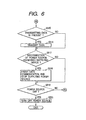
- Figs. 5 and 6 are flowcharts for the processing performed by the power supply device 101.
- the power supply device 101 is powered on and the power source 106 is activated, and at step S502, a minimum power is output to the power reception device 102, which is connected to the power supply device 101.
- step S503 When at step S503 the power reception device 102 is activated, a check is performed to determine whether or not the power supply device 101 is connected to the power reception device 102. When the two are not connected, program control moves to step S511. When the two devices are connected, power capacity request data is transmitted to the power reception device 102. Then, when at step S505 the power source capacity data is received from the power reception device 102, at step S506 the contents of the data is analyzed.
- step S507 If, at step S507, the required power exceeds the available power, program control advances to step S508. When the required power does not exceed the available power that can be supplied, program control moves to step S509. At step S508, the upper supply limit value of the power capacity is set, and is transmitted while being included in power source allowing data. At step S509, the power that is required by the power reception device 102 is set, and the value is transmitted to the device 102 while being included in the power source allowing data.
- step S510 the supply of power from the power supply device 101 to the power reception device 102 is initiated, and data transfer is begun.
- step S511 a check is performed to determine whether there is data to be received. When there is no data to be received, program control goes to step S515. If there is data to be received, at step S512 the data is received and analyzed.
- step S513 the state of the power source receiving/supplying unit 122 is acquired and stored, and at step S514 the state is output to the display unit 110.
- step S515 a check is performed to determine whether there are data to be transmitted. When there are no data to be transmitted, program control moves to step S517. If there are data to be transmitted, at step S516 the data are transmitted.
- step S517 a check is performed to determine whether or not the power reception device 102 has been disconnected. If the power reception device 102 has not been disconnected, program control goes to step S519. If the power reception device 102 has been disconnected, at step S518 data communication is terminated and the supply of power is halted. When, at step S519, the power source 106 has been turned off, at step S520 the power supply device 101 is powered off. If the power source 106 has not been turned off, program control returns to step S511.
- the above disconnection can be, for example, when the connection between the power reception device 102 and the power supply device 101 has been physically severed.
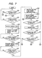
- Figs. 7 and 8 are flowcharts for the processing performed by the power reception device 102.
- step S601 a check is performed to determine whether or not an external power source is on. If the external power is on, program control moves to step S620 in Fig. 8. When the external power source is not on, at step S602 a check is performed to determine whether power is being supplied. If no power is being supplied, program control returns to step S601. When power is being supplied, at step S603 a minimum power requirement that is determined in advance is received from the power supply device 101, and at step S604, the power reception device 102 is connected to the power supply device 101.
- a check is performed to determine whether power request data has been received from the power supply device 101.
- the power reception device 102 waits until the data are received.
- a required power is transmitted as power source capacity data.
- step S607 a check is performed to determine whether power source allowing data has been received. If the data has not yet been received, the power reception device 102 waits until it receives the data.
- the power source allowing data have been received, at step S608 the data is analyzed and a supplied power value is stored in the storage unit 114, and at step S609 power from the power supply device 101 is received.
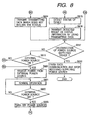
- step S610 a check is performed to determine whether there are data to be received. If there are data to be received, at step S611 the data are received. At step S612 a check is performed to determine whether there are data to be transmitted. If there are no data to be transmitted, program control moves to step S617. If there are data to be transmitted, at step S613 a check is performed to determine whether or not the data to be transmitted indicate the state of the device. When the data do not indicate the state of the device, at step S614 the other data are transmitted, and program control goes to step S617. When the data to be transmitted indicate the state of the device, at step S615 the state of the device is detected.
- the state is periodically detected in a period during which the power reception device 102 is normally operated by power supplied from an external power source. Either each detected state is stored in the storage unit 114, or immediately before power is switched off the state of the device is detected and stored.
- the storage unit 114 for holding the state data employs a battery-backup volatile memory or a nonvolatile memory to hold the state in addition to the previously mentioned supplied power value even when no power is being supplied by the external power source and the power supply device 101. Therefore, necessary information concerning the state of the device can be held.
- the power supply state can be obtained from the state of the power detection unit 201.
- step S616 the thus obtained state of the device is transmitted as status information.
- a check is performed to determine whether or not the power supply device 101 has been disconnected. If the power supply device 101 has been disconnected, at step S618 data communication is terminated, power reception is halted, and processing is thereafter terminated.
- step S619 a check is performed to determine whether or not the external power source is on. If the external power source is off, program control returns to step S610. If the external power source is on, at step S620 the power from the external power source is received and at step S621 normal operation is performed. At step S622, in a period during which the external power source is on, the normal operation is continued. When, at step S622, the external power source is off, at step S623 the power is switched off and program control returns to step S602.
- the operation of the power supply device 101 is disabled because its power switch is off, a user can be notified that the power of the power supply device 101 is off. In other words, a message to turn on the power switch can be provided for a user.
- the state of the power supply device 101 immediately before the power is switched off is stored, the state can be acquired before the power switch is turned on, even when a lack of paper or a paper jam occurs, or insufficient ink or toner remains. Therefore, it is possible to eliminate a wasteful process during which the power is turned on and off again after the state is checked and the unfavorable condition is corrected.
- a small supply of power from a power supply device 101 is effectively employed to detect the internal state of a power reception device 102.
- Fig. 3 is a diagram illustrating the internal arrangement of a power management unit 124.
- a power detection unit 301 determines whether or not power from an external power source is being supplied.
- a power switch 302 selects the power supplied by the external power source if it is available, and selects the power supplied by a power source receiving/supplying unit 122 when no is available from the external power source.
- Switches 303, 304 and 305 are turned on and off when the power from the power switch 302 is supplied to a sensor unit 117. In this embodiment, three switches 1 to 3 are provided.
- Power is supplied directly from the power switch 302 to a control unit 113 and a data I/F unit 115, and power is supplied through the switches 303 to 305 to the respective sensors.
- the control unit 113 employs the switches 303 to 305 to control the supply of power to the individual sensors.
- Power from the external power source is supplied directly to the remaining units.
- the result of the power detection is transmitted to the control unit 113 to notify the control unit 113 of whether or not there is supply of power from the external power source.
- Fig. 4 is a diagram illustrating the internal structure of the sensor unit 117.
- sensors 401, 402 and 403 detect the states of the individual units.
- the sensors 401 to 403 are a sensor (1) for detecting the presence of paper in a paper feeding section; a sensor (2) for detecting the occurrence of paper jams during the paper feeding; and a sensor (3) for detecting the remaining amount of ink or toner.
- the sensors are not limited to the ones described, and any type of sensor can be employed.
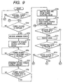
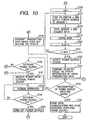
- Figs. 9 and 10 are flowcharts for the processing performed by the power reception device 102 in this embodiment of the invention.
- step S701 a check is performed to determine whether or not an external power source is on. If the external power is on; program control moves to step S727.
- step S702 a check is performed to determine whether there is a supply of power. If there is no supply of power, program control returns to step S701.
- step S703 a minimum power requirement that is determined in advance is received from the power supply device 101, and at step S704, the power reception device 102 is connected to the power supply device 101.
- a check is performed to determine whether power capacity request data has been received from the power supply device 101.
- the power reception device 102 waits until the data is received.
- a required power is transmitted as power source capacity data.
- step S708 a check is performed to determine whether power source allowing data has been received. If the data has not yet been received, the power reception device 102 waits until it receives the data. When the power source allowing data has been received, at step S709 the data is analyzed and a supplied power value is stored, and at step S710 power from the power supply device 101 is received.
- step S711 a check is performed to determine whether there are data to be received. If there are data to be received, at step S712 the data are received. At step S713 a check is performed to determine whether there are data to be transmitted. If there are no data to be transmitted, program control moves to step S718. If there are data to be transmitted, at step S714 a check is performed to determine whether or not the data to be transmitted indicate the state of the device. When the data do not indicate the state of the device, at step S715 the other data are transmitted, and program control goes to step S724. When the data to be transmitted indicate the state of the device, at step S716 n is set to 1.
- step S717 the control unit 113 turns on the switch (1) and supplies power to the sensor (1).
- step S720 n is incremented by one, and at step S721 n is compared with MAX (the number of sensors required for detection).
- program control returns to step S717.
- n is greater than MAX
- the power source status is detected.
- the detected state is transmitted as status information.
- a check is performed to determine whether or not the power supply device 101 has been disconnected. If the power supply device 101 has been disconnected, at step S725 data communication is terminated, power reception is halted, and processing is thereafter terminated.
- step S726 a check is performed to determine whether or not the external power source is on. If the external power source is off, program control returns to step S711. If the external power source is on, at step S727 power from the external power source is received and at step S728 a normal operation is performed. At step S729, during a period in which the external power source is on, the normal operation is continued. When, at step S729, the external power source is off, at step S730 the power is off. Program control thereafter returns to step S702.
- the state in the device can be acquired in advance.
- a message can be provided, notifying a user that the power is off and that the power switch should be turned on.
- the current state of the device can be acquired by sequentially supplying power to the individual sensors, while storing of the state in, for example, nonvolatile memory and the powering on of the device are not required.
- the state can be acquired before the power switch is turned on. Therefore, it is possible to eliminate a wasteful process during which the power is turned on and off again after the state is checked and the unfavorable condition is corrected.
- the state of the power reception device 102 can be acquired even when the power supply capacity of the power supply device 101 is limited.
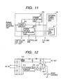
- Fig. 11 is a block diagram illustrating the arrangement according to a second example of a data communication system.
- a power source control unit 203 controls a start switch 211 in an external power source unit 123.
- the start switch (SW) 211 is used to switch between the starting and the halting of the operation of the external power source unit 123.
- Fig. 12 is a circuit diagram for explaining the principle of an example external power source unit 123.
- This circuit constitutes a switching regulator.
- a direct current which is obtained by rectifying and smoothing an AC input, is transmitted to the primary side of a high frequency transformer 212, is switched by a switching element 213, such as a transistor, and is output from the secondary side of the transformer 212.
- a transistor is employed as the start switch 211.
- a control circuit 214, for exercising PWM control of the switching element 213, is connected via a photocoupler 215 to an error amplifier 216.
- a downstream external power source is activated upon a request from a host, and the downstream device is set in an operation enabled state. This process is performed by the power source control unit 203 in the power management unit 124.
- the power supply operation (oscillation of a SW power source) can be completely halted when it is difficult to activate the power source unit.
- a timer is required for the management of an ink-jet head, such as when the stop position of the head is to be defined as a predetermined position, a battery-backed up timer such as is used in a notebook printer can be mounted for managing time.
- a mechanical switch is employed to activate a power source.
- the shutdown of the power source in the power-OFF sequence is logically performed by power supplied by a battery or an I/F (see the block diagram in Fig. 11).
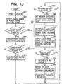
- Figs. 13 and 14 are flowcharts for the processing performed by the power supply device 101.
- the power is on. Since the processes at steps S801 to S814 are the same as those in steps S501 to S514 in Fig. 5, no further explanation for them will be given.
- step S814 the state of the power source receiving/supplying unit 122 is output to the display unit 110
- step S821 a check is performed to determine whether or not the power reception device 102 has requested that an external power source be turned on. If there is no request, program control moves to step S823. If there is such a request, at step S822 data for instructing the turning on of the external power source are transmitted to the power reception device 102.
- step S823 a check is performed to determine whether or not the power reception device 102 has requested that the external power source be turned on. If there is no such request, program control goes to step S815. If there is such a request, at step S824 data for instructing the turning off of the external power source are transmitted to the power reception device 102.
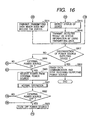
- Figs. 15 and 16 are flowcharts for the processing performed by the power reception device 102.
- an external power source is turned on. Since the processes at steps S901 to S911 are the same as those at steps S601 to S611 in Fig. 7, no further explanation for them will be given.
- step S911 data are received, at step S924 the data are analyzed, and at step S925, a check is performed to determine whether the data constitute an instruction to turn on the external power source. If the data constitute an instruction to turn on the external power source, program control moves to step S920. If the data do not constitute an instruction to turn on the external power source, at step S926 a check is performed to determine whether or not the data constitute an instruction to turn off the external power source. When the data constitute an instruction to turn off the external power source, program control moves to step S923. When the data do not constitute such an instruction, program control goes to step S912.
- step S922 the external power source is not off
- program control goes to step S919. If the external power source is off, at step S923 the power is off. Program control thereafter returns to step S902.
- the external power source of the other device can be activated by a request signal, and usability is, therefore, enhanced.
- the interface between the power source supplying unit 107 and the power source receiving/supplying unit 122, and the interface between the data I/F unit 108 and the I/F unit 115 may be either one called IEEE 1394, or one other than the USB. In other words, any interface by which power can be supplied between the devices can be employed.
- the OFF state of a power switch of a device can be detected without powering on the device. Therefore, a power on instruction can be provided for a user, and usability can be improved.
- the current state or the preceding state of the device can be acquired before the device is powered on.
- the.device is powered on to check the state, then powered off to correct an unfavorable condition, and again powered on for confirmation.
- the usability can be drastically enhanced.
- the external power source of the other device is activated upon the receipt of a request signal, the usability is further improved.
- a computer and a printer have been employed; however, the present invention is not limited to those devices, and can be used effectively for a combination of other devices, such as a computer and a CD-ROM reproduction device.
- the present invention is especially effective when image forming material, such as ink or toner, and a recording medium for a printer are to be replaced while the power is off.
- the above processing can be performed without requiring any special hardware.
- the objects of the present invention can also be achieved by loading, into a system, or a device, a storage medium on which is recorded software program code for accomplishing the functions in the embodiment, and by a computer (a CPU or an MPU) in the system, or in the device, reading and executing the program code that is stored in the storage medium.
- a computer a CPU or an MPU
- the program code that is read from the storage medium implements the functions in the previously mentioned embodiment, and the storage medium on which the program code is stored accomplishes the present invention.
- a storage medium on which program code is recorded is, for example, a floppy disk, a hard disk, an optical disk, a magneto optical disk, a CD-ROM, a CD-R, a magnetic tape, a nonvolatile memory card, or a ROM.
- the present invention also includes a case wherein, to accomplish the functions in the above embodiments, program code read from a storage medium is written in a memory of a function expansion board, which is inserted in a computer or a printer, or a function expansion unit, which is connected to a computer or a printer, and in consonance with a program code instruction, a CPU in the function extension board or the function extension unit performs one part or all of the processing.
Landscapes
- Engineering & Computer Science (AREA)
- Theoretical Computer Science (AREA)
- Physics & Mathematics (AREA)
- General Engineering & Computer Science (AREA)
- General Physics & Mathematics (AREA)
- Accessory Devices And Overall Control Thereof (AREA)
- Monitoring And Testing Of Transmission In General (AREA)
- Selective Calling Equipment (AREA)
- Power Sources (AREA)
Applications Claiming Priority (3)
| Application Number | Priority Date | Filing Date | Title |
|---|---|---|---|
| JP32006196A JPH10164668A (ja) | 1996-11-29 | 1996-11-29 | データ通信システム及びデータ通信装置並びにデータ通信制御プログラムを記録した記録媒体 |
| JP320061/96 | 1996-11-29 | ||
| JP32006196 | 1996-11-29 |
Publications (2)
| Publication Number | Publication Date |
|---|---|
| EP0845736A1 EP0845736A1 (en) | 1998-06-03 |
| EP0845736B1 true EP0845736B1 (en) | 2003-08-06 |
Family
ID=18117290
Family Applications (1)
| Application Number | Title | Priority Date | Filing Date |
|---|---|---|---|
| EP97309567A Expired - Lifetime EP0845736B1 (en) | 1996-11-29 | 1997-11-27 | Data communication system, data communication device and memory medium, for storing data communication program |
Country Status (4)
| Country | Link |
|---|---|
| US (1) | US6016519A (enExample) |
| EP (1) | EP0845736B1 (enExample) |
| JP (1) | JPH10164668A (enExample) |
| DE (1) | DE69723951T2 (enExample) |
Families Citing this family (21)
| Publication number | Priority date | Publication date | Assignee | Title |
|---|---|---|---|---|
| WO1999053627A1 (en) | 1998-04-10 | 1999-10-21 | Chrimar Systems, Inc. Doing Business As Cms Technologies | System for communicating with electronic equipment on a network |
| US6480510B1 (en) * | 1998-07-28 | 2002-11-12 | Serconet Ltd. | Local area network of serial intelligent cells |
| JP2000105638A (ja) | 1998-09-29 | 2000-04-11 | Nec Corp | Usbデバイス及びusb接続システム |
| US6956826B1 (en) | 1999-07-07 | 2005-10-18 | Serconet Ltd. | Local area network for distributing data communication, sensing and control signals |
| US6571181B1 (en) * | 1999-08-11 | 2003-05-27 | Broadcom Corporation | System and method for detecting a device requiring power |
| US6535983B1 (en) * | 1999-11-08 | 2003-03-18 | 3Com Corporation | System and method for signaling and detecting request for power over ethernet |
| US6549616B1 (en) | 2000-03-20 | 2003-04-15 | Serconet Ltd. | Telephone outlet for implementing a local area network over telephone lines and a local area network using such outlets |
| US6701443B1 (en) * | 2000-06-19 | 2004-03-02 | Cisco Technology, Inc. | Methods and apparatus for discovering a powerability condition of a computer network |
| US6961303B1 (en) | 2000-09-21 | 2005-11-01 | Serconet Ltd. | Telephone communication system and method over local area network wiring |
| SG147312A1 (en) * | 2002-07-18 | 2008-11-28 | Seiko Epson Corp | Cartridge and printing apparatus |
| IL152824A (en) * | 2002-11-13 | 2012-05-31 | Mosaid Technologies Inc | A socket that can be connected to and the network that uses it |
| US20050097198A1 (en) * | 2003-10-08 | 2005-05-05 | Getler Robert M. | Printer monitoring system and method |
| US7072995B1 (en) | 2003-12-19 | 2006-07-04 | Emc Corporation | Methods and apparatus for indicating whether a device is connected to a serial ATA communications cable |
| IL159838A0 (en) | 2004-01-13 | 2004-06-20 | Yehuda Binder | Information device |
| US7353407B2 (en) * | 2004-05-20 | 2008-04-01 | Cisco Technology, Inc. | Methods and apparatus for provisioning phantom power to remote devices |
| DE102004046401B4 (de) * | 2004-09-24 | 2006-07-13 | Siemens Ag | Kommunikationssystem, Verteilerelement und Netzwerkgerät |
| US7599485B2 (en) * | 2005-06-24 | 2009-10-06 | Cisco Technology, Inc. | Communications system employing single-pair identity circuit for remotely powered device |
| US7818591B2 (en) | 2007-04-11 | 2010-10-19 | Cisco Technology, Inc. | Techniques for measuring network channel resistive loss between a power-sourcing apparatus and a powered device |
| JP5451327B2 (ja) * | 2009-11-16 | 2014-03-26 | 富士通コンポーネント株式会社 | 電源制御装置 |
| JP2016218592A (ja) * | 2015-05-18 | 2016-12-22 | ファナック株式会社 | パソコンのシャットダウンユニットを備えた工作機械 |
| JP6877901B2 (ja) * | 2016-07-04 | 2021-05-26 | キヤノン株式会社 | 情報処理装置、情報処理方法およびプログラム |
Family Cites Families (7)
| Publication number | Priority date | Publication date | Assignee | Title |
|---|---|---|---|---|
| US4647721A (en) * | 1985-03-19 | 1987-03-03 | Dynatech Computer Power, Inc. | Telephone activated power controller |
| US4691143A (en) * | 1986-09-05 | 1987-09-01 | Aero-Metric General, Inc. | Circuit status indicating device with improved switch on/off detection capability |
| US4864285A (en) * | 1988-05-11 | 1989-09-05 | O G & E | Method and apparatus for testing contacts to determine if opened or closed |
| US5483656A (en) * | 1993-01-14 | 1996-01-09 | Apple Computer, Inc. | System for managing power consumption of devices coupled to a common bus |
| US5506573A (en) * | 1993-05-13 | 1996-04-09 | Server Technology, Inc. | Remote sensor and method for detecting the on/off status of an automatically controlled appliance |
| US5477476A (en) * | 1993-07-14 | 1995-12-19 | Bayview Technology Group, Inc. | Power-conservation system for computer peripherals |
| US5758171A (en) * | 1995-07-05 | 1998-05-26 | Cirrus Logic, Inc. | Apparatus and method for reading back socket power status information |
-
1996
- 1996-11-29 JP JP32006196A patent/JPH10164668A/ja active Pending
-
1997
- 1997-11-27 DE DE69723951T patent/DE69723951T2/de not_active Expired - Lifetime
- 1997-11-27 EP EP97309567A patent/EP0845736B1/en not_active Expired - Lifetime
- 1997-11-28 US US08/980,206 patent/US6016519A/en not_active Expired - Lifetime
Also Published As
| Publication number | Publication date |
|---|---|
| EP0845736A1 (en) | 1998-06-03 |
| US6016519A (en) | 2000-01-18 |
| DE69723951T2 (de) | 2004-06-17 |
| JPH10164668A (ja) | 1998-06-19 |
| DE69723951D1 (de) | 2003-09-11 |
Similar Documents
| Publication | Publication Date | Title |
|---|---|---|
| EP0845736B1 (en) | Data communication system, data communication device and memory medium, for storing data communication program | |
| EP2509030B1 (en) | Image forming apparatus, and control method thereof | |
| CN100525371C (zh) | 打印设备及其控制方法 | |
| CN103248783A (zh) | 打印设备、信息处理设备和打印设备的控制方法 | |
| JP5558925B2 (ja) | 情報処理装置、情報処理装置の制御方法及び制御プログラム | |
| JP6631411B2 (ja) | メンテナンス支援装置、画像形成装置、メンテナンス支援方法、およびコンピュータプログラム | |
| JP2018166281A (ja) | 画像処理装置 | |
| CN112673319B (zh) | 输出半ac波的过零信息的电力供应设备 | |
| US20130061079A1 (en) | Image processing apparatus, method for controlling the same and storage medium | |
| EP2267639B1 (en) | Image forming apparatus | |
| KR20140049932A (ko) | 복수의 전력상태로 가동하는 전자기기 및 그 제어 방법, 및 기억매체 | |
| EP2696565B1 (en) | Power control of an image processing apparatus | |
| JP4507999B2 (ja) | 印刷システムおよび画像読取装置およびその制御方法 | |
| JP2010129042A (ja) | 電源切り換え制御回路、画像形成装置、電源切り換え制御方法、及びコンピュータプログラム | |
| JP4865296B2 (ja) | 情報処理装置及び情報処理方法 | |
| JP2014104654A (ja) | 画像形成装置、画像形成装置の制御方法 | |
| JP2001253152A (ja) | 無停電電源付きデジタル複合機およびその制御方法 | |
| JP2009237985A (ja) | 画像処理装置、制御回路及びプログラム | |
| EP4610780A1 (en) | Information processing apparatus, control method for information processing apparatus, computer program, and storage medium | |
| JP4565618B2 (ja) | 入出力装置および入出力装置の制御方法 | |
| JP2016197324A (ja) | 情報処理装置、情報処理装置の制御方法、及びプログラム | |
| JP2014229975A (ja) | 画像形成装置、画像形成装置の制御方法、及びプログラム | |
| JP2012006179A (ja) | 画像形成装置 | |
| JP2019200514A (ja) | 画像形成システム、画像形成装置、画像形成装置の制御方法、及びプログラム | |
| JP2006007553A (ja) | 記録装置 |
Legal Events
| Date | Code | Title | Description |
|---|---|---|---|
| PUAI | Public reference made under article 153(3) epc to a published international application that has entered the european phase |
Free format text: ORIGINAL CODE: 0009012 |
|
| AK | Designated contracting states |
Kind code of ref document: A1 Designated state(s): DE ES FR GB IT NL |
|
| AX | Request for extension of the european patent |
Free format text: AL;LT;LV;MK;RO;SI |
|
| 17P | Request for examination filed |
Effective date: 19981014 |
|
| AKX | Designation fees paid |
Free format text: DE ES FR GB IT NL |
|
| RBV | Designated contracting states (corrected) |
Designated state(s): DE ES FR GB IT NL |
|
| 17Q | First examination report despatched |
Effective date: 20010109 |
|
| GRAG | Despatch of communication of intention to grant |
Free format text: ORIGINAL CODE: EPIDOS AGRA |
|
| GRAG | Despatch of communication of intention to grant |
Free format text: ORIGINAL CODE: EPIDOS AGRA |
|
| GRAH | Despatch of communication of intention to grant a patent |
Free format text: ORIGINAL CODE: EPIDOS IGRA |
|
| GRAG | Despatch of communication of intention to grant |
Free format text: ORIGINAL CODE: EPIDOS AGRA |
|
| GRAH | Despatch of communication of intention to grant a patent |
Free format text: ORIGINAL CODE: EPIDOS IGRA |
|
| GRAH | Despatch of communication of intention to grant a patent |
Free format text: ORIGINAL CODE: EPIDOS IGRA |
|
| GRAA | (expected) grant |
Free format text: ORIGINAL CODE: 0009210 |
|
| AK | Designated contracting states |
Designated state(s): DE ES FR GB IT NL |
|
| PG25 | Lapsed in a contracting state [announced via postgrant information from national office to epo] |
Ref country code: NL Free format text: LAPSE BECAUSE OF FAILURE TO SUBMIT A TRANSLATION OF THE DESCRIPTION OR TO PAY THE FEE WITHIN THE PRESCRIBED TIME-LIMIT Effective date: 20030806 Ref country code: IT Free format text: LAPSE BECAUSE OF FAILURE TO SUBMIT A TRANSLATION OF THE DESCRIPTION OR TO PAY THE FEE WITHIN THE PRESCRIBED TIME-LIMIT;WARNING: LAPSES OF ITALIAN PATENTS WITH EFFECTIVE DATE BEFORE 2007 MAY HAVE OCCURRED AT ANY TIME BEFORE 2007. THE CORRECT EFFECTIVE DATE MAY BE DIFFERENT FROM THE ONE RECORDED. Effective date: 20030806 Ref country code: FR Free format text: LAPSE BECAUSE OF FAILURE TO SUBMIT A TRANSLATION OF THE DESCRIPTION OR TO PAY THE FEE WITHIN THE PRESCRIBED TIME-LIMIT Effective date: 20030806 |
|
| REG | Reference to a national code |
Ref country code: GB Ref legal event code: FG4D |
|
| REF | Corresponds to: |
Ref document number: 69723951 Country of ref document: DE Date of ref document: 20030911 Kind code of ref document: P |
|
| PG25 | Lapsed in a contracting state [announced via postgrant information from national office to epo] |
Ref country code: ES Free format text: LAPSE BECAUSE OF FAILURE TO SUBMIT A TRANSLATION OF THE DESCRIPTION OR TO PAY THE FEE WITHIN THE PRESCRIBED TIME-LIMIT Effective date: 20031117 |
|
| NLV1 | Nl: lapsed or annulled due to failure to fulfill the requirements of art. 29p and 29m of the patents act | ||
| PLBE | No opposition filed within time limit |
Free format text: ORIGINAL CODE: 0009261 |
|
| STAA | Information on the status of an ep patent application or granted ep patent |
Free format text: STATUS: NO OPPOSITION FILED WITHIN TIME LIMIT |
|
| 26N | No opposition filed |
Effective date: 20040507 |
|
| EN | Fr: translation not filed | ||
| PGFP | Annual fee paid to national office [announced via postgrant information from national office to epo] |
Ref country code: DE Payment date: 20141130 Year of fee payment: 18 Ref country code: GB Payment date: 20141124 Year of fee payment: 18 |
|
| REG | Reference to a national code |
Ref country code: DE Ref legal event code: R119 Ref document number: 69723951 Country of ref document: DE |
|
| GBPC | Gb: european patent ceased through non-payment of renewal fee |
Effective date: 20151127 |
|
| PG25 | Lapsed in a contracting state [announced via postgrant information from national office to epo] |
Ref country code: GB Free format text: LAPSE BECAUSE OF NON-PAYMENT OF DUE FEES Effective date: 20151127 Ref country code: DE Free format text: LAPSE BECAUSE OF NON-PAYMENT OF DUE FEES Effective date: 20160601 |