EP0844718A2 - Dichtungsring aus elastischem Kunststoffmaterial für Kabelgarnituren - Google Patents
Dichtungsring aus elastischem Kunststoffmaterial für Kabelgarnituren Download PDFInfo
- Publication number
- EP0844718A2 EP0844718A2 EP97118547A EP97118547A EP0844718A2 EP 0844718 A2 EP0844718 A2 EP 0844718A2 EP 97118547 A EP97118547 A EP 97118547A EP 97118547 A EP97118547 A EP 97118547A EP 0844718 A2 EP0844718 A2 EP 0844718A2
- Authority
- EP
- European Patent Office
- Prior art keywords
- sealing
- sealing ring
- ring according
- connecting element
- lubricant
- Prior art date
- Legal status (The legal status is an assumption and is not a legal conclusion. Google has not performed a legal analysis and makes no representation as to the accuracy of the status listed.)
- Withdrawn
Links
Images

Classifications
-
- H—ELECTRICITY
- H02—GENERATION; CONVERSION OR DISTRIBUTION OF ELECTRIC POWER
- H02G—INSTALLATION OF ELECTRIC CABLES OR LINES, OR OF COMBINED OPTICAL AND ELECTRIC CABLES OR LINES
- H02G15/00—Cable fittings
- H02G15/08—Cable junctions
- H02G15/18—Cable junctions protected by sleeves, e.g. for communication cable
- H02G15/192—Cable junctions protected by sleeves, e.g. for communication cable with support means for ends of the sleeves
-
- H—ELECTRICITY
- H02—GENERATION; CONVERSION OR DISTRIBUTION OF ELECTRIC POWER
- H02G—INSTALLATION OF ELECTRIC CABLES OR LINES, OR OF COMBINED OPTICAL AND ELECTRIC CABLES OR LINES
- H02G15/00—Cable fittings
- H02G15/013—Sealing means for cable inlets
-
- H—ELECTRICITY
- H02—GENERATION; CONVERSION OR DISTRIBUTION OF ELECTRIC POWER
- H02G—INSTALLATION OF ELECTRIC CABLES OR LINES, OR OF COMBINED OPTICAL AND ELECTRIC CABLES OR LINES
- H02G15/00—Cable fittings
- H02G15/08—Cable junctions
- H02G15/10—Cable junctions protected by boxes, e.g. by distribution, connection or junction boxes
- H02G15/113—Boxes split longitudinally in main cable direction
Definitions
- the invention relates to a sealing ring made of elastic Plastic material for seals in a sealing groove between a disc-shaped sealing body and a attached sleeve pipe for cable fittings.
- tubular round seals in sealing areas between the front sealing bodies and the socket pipe a cable set is common.
- Such round seals are used as elongated sections, in their ends a connecting link or connecting element in the inner openings the tubular round seal for bridging the joint is introduced.
- Such tubular round seal with an inserted bridging element is generally sufficient for the posed Claims.
- Such embodiments with circular Cross-section are from the European patent application EP 0 417 608 - A2 and European patent EP 0 443 118 - B1 known, which is described in the latter document, that in addition to the bridging song in the ends of the round seal Coupling links used in the form of locking elements are.
- the object of the present invention is now a seal for the Use for cable sleeves in the sealing area of the sleeve pipe / sealing body to create their construction in the joint area simplified and their sealing relationships in the entire sealing area are improved.
- the task is accomplished with a sealing ring at the beginning explained type solved in that the sealing ring X-shaped cross-section, so that parallel, circumferential Sealing lines through the ends of the X-shape in the sealing groove of the sealing system are formed with each in between lying circumferential longitudinal cavities in the form of depressions.
- This sealing ring can be used both as an endlessly glued or as a divided sealing unit that can be connected with a connecting element.
- An elastomer such as silicone rubber, is used for the sealing ring, which can also be strikingly colored, for example.
- the glued version uses a plastic adhesive, for example Elastosil E41 from Wacker, but other adhesives that are matched to the material of the sealing ring used can also be used.
- the material of the sealing ring which is made of solid material, has a shore hardness of 40 ° ⁇ 20 or 30 ⁇ 5.
- the split sealing ring which is only endless during assembly is made at both ends with sack-shaped slots provided, in the connecting element bridging the joint is used.
- This connecting element must be anchored non-slip. Such an anti-slip device will for example by placing barbs on the surface of the link reached. This will cause it to slip out largely prevented.
- This is expedient Connecting element in the circumferential direction on the corresponding Seal body diameter pre-bent so that in this No tension due to deformation.
- the connecting element is made of plastic or metal, preferably made of stainless steel.
- the peculiarity of the sealing ring is that the strand made of solid material has a cross section, which creates several parallel circumferential sealing lines lets, with circumferential between these sealing lines Longitudinal cavities are formed.
- Suitable as a cross section according to the invention in particular, a rectangular shape, which to the Corners are rounded and their side surfaces are longitudinal are dented so that when applied to flat sealing surfaces the sealing groove with two longitudinal cavities lateral sealing lines are formed.
- Cross-sectional shape is essentially similar to an X shape, like that Cross-sectional shape of the sealing ring according to the invention Simplicity continues to be referred to.
- This form of expression is also chosen in claim 1 to design characterize the cross section of the sealing ring in a concise form to be able to.
- displaying the X shape also more clearly what is meant when their ends longitudinal sealing lines arise when fitting leave between which longitudinal sealing cavities are formed.
- a lubricant such as silicone grease
- silicone grease is applied in the sealing groove or on the sealing ring when inserting the sealing ring in order to improve the sealing conditions.
- the lubricant is easily replaced by a With the cross-sectional shape according to the invention, it is advantageous that a lubricant reservoir is formed to a certain extent in the longitudinal cavities which are formed, so that the lubricant does not get out of the sealing zone by wiping effects when the sealing ring moves relative to the socket pipe Will get removed.
- the material for the sealing ring is in its elasticity and generally optimized in hardness so that all Requirements with low temperature application are met.
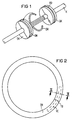
- FIG. 1 it is shown that the sealing ring DR according to the invention on the scope of a sealing body DK in one Sealing groove DN is used.
- the sealing body DK are located at the front ends of a cable assembly, a sleeve pipe after inserting the sealing ring DR is raised.
- the cables are inside the cable set K spliced.
- FIG. 2 now illustrates a sealing ring DR in a front view, that of an elongated strand of an elastomer, such as silicone rubber, assembled into a circular shape becomes.
- This merge can be done either Adhesive at the separation point TS or by composition with the help of a connecting element VE, the Inserted inside the sealing ring DR in sack-shaped slots is and bridges the separation point TS.
- Section III-III indicated, which is the basis of Figure 3.
- FIG 3 is a cross section through the sealing ring DR shown that this is not a hose seal but a seal that is continuous consists of an elastomer. Only in the area of the separation point TS (see Figure 2) are bag-shaped slots S at the ends arranged, in which, if necessary, a connecting element VE for Bridging the separation point TS is introduced. If the Sealing strand is made by extrusion, however there is a continuous longitudinal cavity.
- the cross-sectional shape of the sealing ring DR according to the invention is rough Measured rectangular. But the corners of this shape are rounded and the side boundaries are inward dented so that depressions ES are formed.
- These depressions ES form seen on the circumference of the sealing ring DR circumferential longitudinal cavities between two near each the margins EH. With that form Insert of the sealing ring DR along the walls of the Sealing groove each two sealing lines, between which the longitudinal cavities of the depressions ES extend. In order to is compared to a conventional round seal with only one Sealing line a significant improvement in the sealing conditions reached. They also take longitudinal cavities when using an additional lubricant first excess lubricant so that the previously occurring Wiping effect and thus the risk of irregularities in the Sealing area can be largely avoided.
- the brought in Lubricant GM is dashed in Figure 3 indicated.
- the cross-section of the sealing ring DR is based on the previous one Description in the basic form also to be regarded as an X-shaped.
- the elevations EH form the ends of the X shape, each designed more or less as sealing lips after training are. After inserting them into the walls of the sealing groove the sealing lines.
- the depressions lie in between ES the longitudinal cavities between the X ends.
- the cross-sectional design characterize the sealing ring according to the invention, as included in this short form in claim 1 is.
- FIG 4 is an embodiment of a connecting element VE shown. It consists of a metal band, for example from 0.8 mm thick stainless steel, or from Plastic and has barbs WH along the surface on that a migration out of the slots of the sealing ring prevent. In the middle of the connecting element VE a middle display MM may be attached.
- the connecting element VE is expediently in the circumferential direction Radius of the sealing body used pre-bent accordingly, so that a trouble-free edition in the area of Separation point is given.
Landscapes
- Cable Accessories (AREA)
- Installation Of Indoor Wiring (AREA)
- Gasket Seals (AREA)
Abstract
Description
- Aufgrund der geringeren Auflagefläche ergeben sich entlang der Dichtlinien höhere Dichtkrafte bei unveränderter Gesamtkraft gegen das Muffenrohr.
- Durch die erhöhte Dichtkraft entlang der Dichtlinien kann das Inlet als Gegenlager für die Längsdichtung entfallen
- Zwei Dichtzonen unterbrechen den Leckpfad und erhöhen dadurch die Dichtsicherheit.
- Die Längshohlräume zwischen den beiden Dichtlinien dienen als Gleitmittelreservat, so daß bei Relativbewegungen zwischen dem Dichtungsring und dem Muffenrohr genügend Gleitmittel zur Verfügung steht.
- Aufgrund des neuen Querschnitts beträgt der gesamte Verformungsweg im Dichtungssystem, das ist der Weg, den das Muffenrohr beim Verschließen zurücklegen muß, nur noch 2 mm gegenüber vormals 4 mm. Dadurch ergeben sich einfachere Verschlußverhältnisse.
- Die gesamte Verformung des Dichtungsringes erfolgt nun durch elastische Verformung des Dichtmaterials; Biegekräfte sind dadurch an der Dichtkraft nur noch minimal beteiligt.
- Keine bzw. nur minimale Unstetigkeit über dem Umfang. Dadurch kann das Muffenrohr über den ganzen Umfang auf dem Dichtungskörperflansch aufliegen, so daß das Eindringen von Schmutz in den Dichtungsbereich verhindert wird. Bei bisherigen Ringdichtungen ergaben sich unterschiedliche Querschnitte infolge von Einlagen innerhalb der Ringdichtung.
- Figur 1
- verdeutlicht den Einsatz eines Dichtungsringes bei einer Kabelgarnitur.
- Figur 2
- zeigt den geschlossenen Dichtungsring.
- Figur 3
- zeigt den Querschnitt des Dichtungsringes.
- Figur 4
- zeigt ein Verbindungselement für den geteilten Dichtungsring.
Claims (9)
- Dichtungsring aus elastischem Kunststoffmaterial für Abdichtungen in einer Dichtungsnut zwischen einem scheibenförmigen Dichtungskörper und einem aufgesetzten Muffenrohr bei Kabelgarnituren,
dadurch gekennzeichnet,
daß der Dichtungsring (DR) X-förmigen Querschnitt aufweist, so daß parallele umlaufende Dichtungslinien durch die Enden der X-Form in der Dichtungsnut (DN) gebildet sind mit jeweils dazwischen liegenden umlaufenden Längshohlräumen in Form von Einsenkungen (ES). - Dichtungsring nach Anspruch 1,
dadurch gekennzeichnet,
daß er aus einem langgestreckten Strang ringförmig zusammengeführt und in der Trennstelle (TS) mit einem Kunststoffkleber verklebt ist. - Dichtungsring nach Anspruch 1,
dadurch gekennzeichnet,
daß er (DR) aus einem langgestreckten Strang besteht, in dem zumindest an beiden Enden Schlitze (S) angeordnet sind und daß in die Schlitze (S) ein Verbindungselement (VE) die Trennstelle (TS) überbrückend eingesetzt ist. - Dichtungsring nach Anspruch 3,
dadurch gekennzeichnet,
daß das Verbindungsglied (VE) aus einem zugfesten Band aus Metall, vorzugsweise aus rostfreiem Stahl, oder aus Kunststoff besteht. - Dichtungsring nach Anspruch 3 oder 4,
dadurch gekennzeichnet,
daß das Verbindungselement (VE) Widerhaken (WH) aufweist. - Dichtungsring nach einem der Ansprüche 3 bis 5,
dadurch gekennzeichnet,
daß das Verbindungselement (VE) dem Durchmesser des Dichtungskörpers (DK) entsprechend vorgeformt ist. - Dichtungsring nach einem der vorhergehenden Ansprüche,
dadurch gekennzeichnet,
daß ein Gleitmittel, z.B. Silikonfett auf den Dichtflächen aufgebracht ist. - Dichtungsring nach Anspruch 7,
dadurch gekennzeichnet,
daß die als Längshohlräume ausgebildeten Einsenkungen (ES) mit einem Gleitmittel (GM) gefüllt sind. - Dichtungsring nach einem der vorhergehenden Ansprüche,
dadurch gekennzeichnet,
daß das Verbindungselement (VE) eine Mittenanzeige (MM) aufweist.
Applications Claiming Priority (2)
| Application Number | Priority Date | Filing Date | Title |
|---|---|---|---|
| DE19648293 | 1996-11-21 | ||
| DE19648293 | 1996-11-21 |
Publications (2)
| Publication Number | Publication Date |
|---|---|
| EP0844718A2 true EP0844718A2 (de) | 1998-05-27 |
| EP0844718A3 EP0844718A3 (de) | 1999-02-03 |
Family
ID=7812404
Family Applications (1)
| Application Number | Title | Priority Date | Filing Date |
|---|---|---|---|
| EP97118547A Withdrawn EP0844718A3 (de) | 1996-11-21 | 1997-10-24 | Dichtungsring aus elastischem Kunststoffmaterial für Kabelgarnituren |
Country Status (1)
| Country | Link |
|---|---|
| EP (1) | EP0844718A3 (de) |
Cited By (2)
| Publication number | Priority date | Publication date | Assignee | Title |
|---|---|---|---|---|
| WO2000016458A1 (de) * | 1998-09-16 | 2000-03-23 | Rxs Gesellschaft Für Vermögensverwaltung Mbh | Verbindungselement zur überbrückung der trennstelle einer geteilten dichtung bei einer kabelgarnitur |
| US6231051B1 (en) * | 1997-12-09 | 2001-05-15 | Rxs Kabelgarnituren Gmbh | Cable sleeve consisting of a socket pipe having at least one transversely divided end member |
Family Cites Families (7)
| Publication number | Priority date | Publication date | Assignee | Title |
|---|---|---|---|---|
| AT332687B (de) * | 1974-12-12 | 1976-10-11 | Vaillant Gmbh | Gliederkessel |
| DE3426805A1 (de) * | 1984-07-20 | 1986-01-23 | INA Wälzlager Schaeffler KG, 8522 Herzogenaurach | Abdichtung |
| DE3689459D1 (de) * | 1985-10-14 | 1994-02-10 | Siemens Ag | Kabelmuffe mit stirnseitigen Dichtungskörpern und einem längsgeschlitzten Muffenrohr. |
| EP0417608A3 (en) * | 1989-09-13 | 1991-07-31 | Siemens Aktiengesellschaft | Split round seal for sealing body of cable fittings |
| EP0443118B1 (de) * | 1990-02-23 | 1995-01-25 | RXS Schrumpftechnik-Garnituren GmbH | Geteilter Dichtungsring aus Kunststoff für Dichtungskörper bei Kabelgarnituren |
| DE4039071A1 (de) * | 1990-12-07 | 1992-06-11 | Philips Patentverwaltung | Rundschnurdichtungsring |
| US5170017A (en) * | 1991-02-15 | 1992-12-08 | Augat Inc. | Connector and method for sealed pass-through of insulated electrical conductors |
-
1997
- 1997-10-24 EP EP97118547A patent/EP0844718A3/de not_active Withdrawn
Cited By (3)
| Publication number | Priority date | Publication date | Assignee | Title |
|---|---|---|---|---|
| US6231051B1 (en) * | 1997-12-09 | 2001-05-15 | Rxs Kabelgarnituren Gmbh | Cable sleeve consisting of a socket pipe having at least one transversely divided end member |
| WO2000016458A1 (de) * | 1998-09-16 | 2000-03-23 | Rxs Gesellschaft Für Vermögensverwaltung Mbh | Verbindungselement zur überbrückung der trennstelle einer geteilten dichtung bei einer kabelgarnitur |
| AU757213B2 (en) * | 1998-09-16 | 2003-02-06 | Ccs Technology, Inc. | Joining element for bridging the separating area of a divided seal in cable fittings |
Also Published As
| Publication number | Publication date |
|---|---|
| EP0844718A3 (de) | 1999-02-03 |
| MX9708941A (es) | 1998-05-31 |
Similar Documents
| Publication | Publication Date | Title |
|---|---|---|
| DE4229609C2 (de) | Abdichtung zwischen zwei ineinandersteckbaren Teilen | |
| DE69212624T2 (de) | Schutzhülle und Verfahren zum Aufbringen der Schutzhülle auf einen zu schützenden Gegenstand | |
| EP0521324B2 (de) | Kabelmuffe | |
| DE69501803T2 (de) | Wasserfeste Dichtung für Verbinder | |
| DE3941268C2 (de) | ||
| DE4220208A1 (de) | Schlauchkupplung | |
| DE3446427C2 (de) | ||
| DE2609576A1 (de) | Kupplungsmuffe | |
| DE3826622A1 (de) | Dichtung fuer muffenrohrverbindungen | |
| EP0844718A2 (de) | Dichtungsring aus elastischem Kunststoffmaterial für Kabelgarnituren | |
| EP0402653A2 (de) | Kabeleinführungsdichtung | |
| EP1323958A1 (de) | Dichtring | |
| DE202008005936U1 (de) | Kupplung zum Verbinden zweier Rohrenden mit sekundärer Quelldichtung | |
| DE19711003C2 (de) | Verankerungsvorrichtung für ein Zugglied, insbesondere für die Anwendung im Spannbetonbau | |
| EP1313981B1 (de) | Verbindungseinrichtung für schutzrohre | |
| EP0765020A2 (de) | Anordnung zum dichten Umschliessen eines Substrates | |
| DE2413057C3 (de) | Anschlußstück eines biegsamen Schlauches | |
| EP0443118B1 (de) | Geteilter Dichtungsring aus Kunststoff für Dichtungskörper bei Kabelgarnituren | |
| DE1650052A1 (de) | Flexible Schlauchleitung,insbesondere fuer den Transport biphasischer,unter Druck stehender Medien | |
| DE2742760A1 (de) | Elastische abdichtung von trennfugen zwischen dichtungskoerpern und muffenrohr sowie von trennebenen des muffenrohres bei thermoplastklemmuffen | |
| DE3632164C2 (de) | ||
| DE1902520A1 (de) | Formstuecke fuer Rohrverbindungen | |
| EP1200757A1 (de) | Elastische ringdichtung | |
| AT399549B (de) | Biegsames rohr mit einer rohrwand aus einem gewindeartigen gewickelten bandstreifen | |
| DE4114232A1 (de) | Muffenverbindung fuer rohre oder profile |
Legal Events
| Date | Code | Title | Description |
|---|---|---|---|
| PUAI | Public reference made under article 153(3) epc to a published international application that has entered the european phase |
Free format text: ORIGINAL CODE: 0009012 |
|
| AK | Designated contracting states |
Kind code of ref document: A2 Designated state(s): AT BE CH DE DK ES FI FR GB GR IE IT LI LU MC NL PT SE |
|
| PUAL | Search report despatched |
Free format text: ORIGINAL CODE: 0009013 |
|
| AK | Designated contracting states |
Kind code of ref document: A3 Designated state(s): AT BE CH DE DK ES FI FR GB GR IE IT LI LU MC NL PT SE |
|
| 17P | Request for examination filed |
Effective date: 19990319 |
|
| 17Q | First examination report despatched |
Effective date: 19990802 |
|
| AKX | Designation fees paid | ||
| REG | Reference to a national code |
Ref country code: DE Ref legal event code: 8566 |
|
| STAA | Information on the status of an ep patent application or granted ep patent |
Free format text: STATUS: THE APPLICATION IS DEEMED TO BE WITHDRAWN |
|
| 18D | Application deemed to be withdrawn |
Effective date: 20000304 |