EP0844151A2 - Dispositif de retenue de passagers d'un véhicule - Google Patents
Dispositif de retenue de passagers d'un véhicule Download PDFInfo
- Publication number
- EP0844151A2 EP0844151A2 EP97119538A EP97119538A EP0844151A2 EP 0844151 A2 EP0844151 A2 EP 0844151A2 EP 97119538 A EP97119538 A EP 97119538A EP 97119538 A EP97119538 A EP 97119538A EP 0844151 A2 EP0844151 A2 EP 0844151A2
- Authority
- EP
- European Patent Office
- Prior art keywords
- webbing
- retractor
- guide bar
- seat back
- guide structure
- Prior art date
- Legal status (The legal status is an assumption and is not a legal conclusion. Google has not performed a legal analysis and makes no representation as to the accuracy of the status listed.)
- Withdrawn
Links
Images


Classifications
-
- B—PERFORMING OPERATIONS; TRANSPORTING
- B60—VEHICLES IN GENERAL
- B60R—VEHICLES, VEHICLE FITTINGS, OR VEHICLE PARTS, NOT OTHERWISE PROVIDED FOR
- B60R22/00—Safety belts or body harnesses in vehicles
- B60R22/18—Anchoring devices
- B60R22/26—Anchoring devices secured to the seat
-
- B—PERFORMING OPERATIONS; TRANSPORTING
- B60—VEHICLES IN GENERAL
- B60N—SEATS SPECIALLY ADAPTED FOR VEHICLES; VEHICLE PASSENGER ACCOMMODATION NOT OTHERWISE PROVIDED FOR
- B60N2/00—Seats specially adapted for vehicles; Arrangement or mounting of seats in vehicles
- B60N2/68—Seat frames
- B60N2/688—Particular seat belt attachment and guiding
-
- B—PERFORMING OPERATIONS; TRANSPORTING
- B60—VEHICLES IN GENERAL
- B60R—VEHICLES, VEHICLE FITTINGS, OR VEHICLE PARTS, NOT OTHERWISE PROVIDED FOR
- B60R22/00—Safety belts or body harnesses in vehicles
- B60R22/18—Anchoring devices
- B60R2022/1818—Belt guides
Definitions
- the present invention relates to a seat belt system for restraining a vehicle occupant, and particularly relates to a seat-integrated seat belt system which is supported on a vehicle seat.
- a seat belt system directs seat belt webbing to extend across an occupant of a vehicle seat.
- one end of the webbing is wound on a spool in a retractor, and the other end of the webbing is connected to a webbing anchor.
- the retractor and the anchor are both fixed to the vehicle at one side of the seat.
- a tongue is slidable along the length of the webbing.
- the system further includes a buckle which is fixed to the vehicle at the opposite side of the seat. When the tongue on the webbing is locked in the buckle, a lap belt section of the webbing extends from the anchor to the tongue across the occupant's lap.
- a shoulder belt section of the webbing extends from the retractor to the tongue across the occupant's torso. It may be desirable to adjust the height of the shoulder belt section of the webbing, in accordance with the size of the vehicle occupant.
- an apparatus comprises seat belt webbing, a seat belt retractor, and means for mounting the retractor on a shoulder portion of a seat back.
- the apparatus further comprises a guide structure having an elongated turning surface which engages the webbing to define a turn in the webbing.
- Another mounting means mounts the guide structure on an opposite shoulder portion of the seat back with the turning surface in a vertically extending orientation.
- the guide structure supports the webbing for movement along and around the turning surface upon extraction and retraction of the webbing when a shoulder belt section of the webbing is moved back and forth across the seat back.
- An apparatus constructed in accordance with the present invention enables the shoulder belt section of the webbing to fit comfortably against the shoulder of a seated vehicle occupant. This is because the guide structure supports the webbing for vertical movement along the length of the turning surface so that the height of the shoulder belt can vary in accordance with the size of the vehicle occupant.
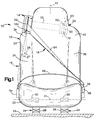
- the apparatus 10 includes a vehicle seat 12 and a seat belt system 14.
- the seat belt system 14 includes seat belt webbing 16 for restraining an occupant of the seat 12.
- the seat belt system 14 is a seat-integrated system which is supported entirely on the seat 12.
- the seat 12 includes a seat back 20 and a seat bottom or cushion 22.
- the seat cushion 22 is supported on a pair of track assemblies 24 (shown schematically) which are fixed to the vehicle floor 26.
- Each track assembly 24 includes a respective bearing assembly 28.
- the bearing assemblies 28 enable the seat 12 to slide along the track assemblies 24 for adjustment of the position of the seat 12.
- Additional bearing assemblies 30 support the seat back 20 for pivotal movement about a horizontal axis 31. Raising and lowering of the seat back 20 pivotally about the axis 31, as well as movement of the seat 12 along the track assemblies 24, can be controlled by any suitable manual and/or motorized mechanism (not shown) known in the art.
- the seat back 20 is elongated vertically, and thus has a vertically extending longitudinal centerline 33.
- vertically extending it is meant that the centerline 33 is vertical, substantially vertical, or inclined within a range corresponding to the range throughout which the seat back 20 can be raised or lowered pivotally about the horizontal axis 31.
- a right hand side 34 of the seat back 20 is located to the left of the centerline 33 in Fig. 1
- a left hand side 36 of the seat back 20 is located to the right of the centerline 33 in Fig. 1.
- the right hand side 34 of the seat back 20 has a right shoulder portion 38.
- the left hand side 36 of the seat back 20 has a left shoulder portion 40.
- the right and left hand sides 34 and 36 of the seat back 20 are hereafter referred to as the first and second sides, with first and second shoulder portions 38 and 40, respectively.
- the seat belt system 14 includes a retractor 50 and a guide structure 52.
- the retractor 50 is mounted on the second shoulder portion 40 of the seat back 20, and is fully enclosed within the seat back 20.
- the guide structure 52 is mounted on the first shoulder portion 38 of the seat back 20, and can be partially or fully enclosed within the seat back 20 cushions and trim.
- a concealed upper section 55 of the webbing 16 extends across the inside of the seat back 20 from the retractor 50 to the guide structure 52.
- the webbing 16 further extends downward along the outside of the seat back 20 to a webbing anchor 54 on the seat cushion 22.
- a tongue 56 is slidable along the length of the webbing 16, and is releasably lockable in a buckle 58 at the opposite side of the seat cushion 22.
- the retractor 50 is shown schematically in Fig. 1.
- the retractor 50 has a spool 60 upon which the webbing 16 is wound.
- a rewind spring 62 biases the spool 60 to rotate about an axis 63 in a winding direction.
- the webbing 16 is movable back and forth between a fully retracted position and a fully extracted position upon winding and unwinding of the webbing 16 on the spool 60.
- the webbing 16 When the webbing 16 is in the fully retracted position, it is fully wound onto the spool 60, and extends downward from the guide structure 52 along the first side 34 of the seat back 20, as shown in dashed lines in Fig. 1.
- the webbing 16 When the webbing 16 is in the fully extracted position, as shown in solid lines in Fig. 1, it is fully unwound from the spool 60, and is extracted from the retractor 50 sufficiently to enable the tongue 56 to reach the buckle 58.
- a shoulder belt section 64 of the webbing 16 then extends across the seat 12 from the guide structure 52 to the tongue 56.
- a lap belt section 66 of the webbing 16 extends across the seat 12 from the anchor 54 to the tongue 56.
- the rewind spring 62 in the retractor 50 is stressed as the spool 60 rotates in an unwinding direction when a vehicle occupant extracts the webbing 16 from the retractor 50 and moves the tongue 56 toward the buckle 58.
- the rewind spring 62 rotates the spool 60 in the winding direction to retract the webbing 16 into the retractor 50, and thereby to move the webbing 16 back to the fully retracted position.
- the retractor 50 further includes a locking mechanism 70 for blocking unwinding rotation of the spool 60 upon the occurrence of a crash or other emergency condition for which the webbing 16 is required to restrain an occupant of the seat 12.
- the locking mechanism 70 is gimballed in a known manner to compensate for changes in the seat back angle.
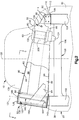
- the retractor 50 and the guide structure 52 are located at opposite ends of a bracket 80 which extends horizontally across the seat back 20 between the first and second shoulder portions 38 and 40.
- the bracket 80 has a horizontally elongated base wall 82 with a first tapered portion 84, an intermediate portion 86, and a second tapered portion 88.
- the first tapered portion 84 of the base wall 82 has an edge 90 defining a first, relatively wide end of the bracket 80.
- the second tapered portion 88 of the base wall 82 has an edge 92 defining a second, relatively narrow end of the bracket 80.
- the bracket 80 further has upper and lower flanges 94 and 96.
- the flanges 94 and 96 extend fully along the length of the first tapered portion 84 of the base wall 82, and face toward each other across the width of the first tapered portion 84.
- the flanges 92 and 94 and the first tapered portion 84 of the base wall 82 together define a tapered, channel-shaped passage 98 extending longitudinally between the first end 90 of the bracket 80 and the intermediate portion 86 of the base wall 92.
- the upper flange 94 and the lower flange 96 include tabs 94A and 96A, respectively, which extend at right angles to the axis 131 of the guide bar 130 (described below).
- a large hole in the lower tab 96A is sized to locate the bracket 80 on the guide bar 130 while a smaller hole in the upper tab 94A is sized to locate the bracket 80 on the upper shoulder 130B of the guide bar 130.
- the seat back 20 has a frame structure 100.
- the frame structure 100 includes a first vertically extending beam 102, a second vertically extending beam 104, and a cross member 106 extending horizontally between the first and second beams 102 and 104.
- the bracket 80 is mounted on the frame structure 100 at the second shoulder portion 40 of the seat back 20.
- the second vertically extending beam 104 has an upper end 108 at the second shoulder portion 40 of the seat back 20.
- An extension structure 110 is fixed to the second beam 104 by a weld 112 at the upper end 108 of the second beam 104.
- the second tapered portion 88 of the base wall 82 is fixed to the extension structure 110 by a plurality of spot welds 114.
- the retractor 50 is mounted on the bracket 80 at the intermediate portion 86 of the base wall 82.
- the retractor 50 has a base plate 120 which supports the spool 60.
- the base plate 120 further supports a housing 122 which contains the rewind spring 62 (Fig. 1), and another housing 124 which contains the emergency locking mechanism 70.
- a fastener 126 fastens the base plate 120 to the intermediate portion 86 of the base wall 82.
- the retractor 50 is thus mounted on the second shoulder portion 40 of the seat back 20 in a position in which the spool axis 63 has a vertically extending orientation.
- the guide structure 52 is located at the first shoulder portion 38 of the seat back 20 adjacent to the first end 90 of the bracket 80. As shown in Figs. 2 and 5, the guide structure 52 includes a cylindrical guide bar 130.
- the guide bar 130 has a longitudinal central axis 131, and is contained within a generally cylindrical sleeve 132.
- the axis 131 of the guide bar 130 has a vertically extending orientation, and is preferably parallel to the spool axis 63 (Fig. 2).
- the guide structure 52, and hence the axis 131 of the guide bar 130 is tilted slightly toward an adjacent headrest portion 134 of the seat back 20 so as to have an orientation which is complementary to the shape of the seat back 20.
- a cover portion 136 of the guide structure 52 encloses the sleeve 132 and the guide bar 130.
- the guide bar 130 is mounted on the first beam 102 in the seat back 20 in the manner shown in Figs. 6 and 7.
- the first beam 102 has a hollow upper end portion 140.
- a pair of support blocks 142 and 144 are closely received within the upper end portion 140 of the first beam 102.
- a cylindrical support shaft 146 extends longitudinally through passages 148 and 150 in the support blocks 142 and 144, respectively.
- the support shaft 146 has an upper end portion 152 projecting upward from the first beam 102 along the axis 131.
- a pair of fasteners 154 fasten the support shaft 146 and the support blocks 142 and 144 immovably to the first beam 102.
- the guide bar 130 has a hollow lower end portion 156 which is closely received telescopically over the upper end portion 152 of the support shaft 146.
- the guide bar 130 is immovably fastened to the support shaft 146 by another fastener 158.
- the sleeve 132 which contains the guide bar 130, has a pair of longitudinally extending slots 160 and 162. As best shown in Fig. 2, the first slot 160 is parallel to the axis 131 along nearly its entire length, but has a short lower end portion 164 which turns away from the axis 131.
- the second slot 162 (Fig. 5) is parallel to the axis 131 along its entire length, and is wider than the first slot 160.
- the sleeve 132 rotates on the guide bar 130 outer surfaces at 130B and 130C. Rotation of the sleeve 132 is limited to about 30° by the shape of the upper tab 94A on the bracket 80 and the width of the slot 162 in the sleeve 132, as shown in Fig. 5. This rotation permits the slots 160 and 162 to align with the webbing 16 so that the normal force and friction of the webbing 16 in contact with the sleeve 132 is minimized.
- the cover portion 136 of the guide structure 52 has a trough-shaped body wall 170 with an arcuate base portion 172 and a pair of parallel, planar side portions 174 and 176.
- the base portion 172 of the body wall 170 has a semi-cylindrical shape centered on the axis 131.
- One side portion 174 of the body wall 170 is fixed to a vertically elongated spacer channel 178 by a pair of fasteners 180, one of which is shown in Fig. 5.
- the spacer channel 178 is fixed to the base wall 82 of the bracket 80 by a vertically extending weld 182.
- the other side portion 176 of the body wall 170 has a vertically elongated slot 184. As best shown in Fig.
- the slot 184 in the cover 136 is substantially wider than, and is located in front of, the first slot 160 in the sleeve 132.
- a fastener 186 (Fig. 2) at the upper end of the guide structure 52 fastens the cover 136 immovably to the guide bar 130.
- the guide bar 130 engages the webbing 16 so as to define a turn 190 in the webbing 16.
- the turn 190 in the webbing 16 extends partially around a vertically elongated, cylindrical outer surface 192 of the guide bar 130.
- the shoulder belt section 64 of the webbing 16 projects tangentially from the cylindrical outer surface 192 of the guide bar 130. The shoulder belt section 64 thus extends outward through the first slot 160 in the sleeve 132, and further outward through the adjacent slot 184 in the cover 136.
- the upper section 55 of the webbing 16 also projects tangentially from the cylindrical outer surface 192 of the guide bar 130.
- the upper section 55 of the webbing 16 thus extends from the guide bar 130 into the passage 98 through the second slot 162 in the sleeve 132, and continues longitudinally through the passage 98 toward the retractor 50 (Fig. 2).
- the upper section 55 of the webbing 16 is enclosed within the passage 98 by a plastic cover panel 194.
- the cover panel 194 extends between the flanges 94 and 96 opposite the base wall 82 of the bracket 80, and is preferably fixed to the flanges 94 and 96 by clips 195 molded into the cover panel 194.
- the cover panel 194 and the three walls of the bracket 80 form a protective enclosure so that the motion of the webbing 16 will not be obstructed by the seat cushion materials.
- the webbing 16 When the webbing 16 is moved back and forth between the positions shown in Fig. 1, it moves along and around the cylindrical outer surface 192 of the guide bar 130. Specifically, the webbing 16 slides circumferentially around the cylindrical outer surface 192 of the guide bar 130 whenever it is extracted or retracted upon being unwound from, or wound onto, the retractor spool 60.
- the shoulder belt section 64 of the webbing 16 When the tongue 56 is locked in the buckle 58, the shoulder belt section 64 of the webbing 16 is drawn against the torso of the seated occupant under tension induced by the rewind spring 62 in the retractor 50. If the occupant is of a relatively small size, the shoulder belt section 64 will thus take a position at or near the position in which it is shown in Fig. 1.
- a low friction coating 196 (Fig. 8) is preferably provided on the cylindrical outer surface 190 of the guide bar 130 to promote sliding movement of the webbing 16 along and around the guide bar 130 in this manner.
- the coating 196 may be formed of any suitable material known in the art.
- the range through which the webbing 16 can slide vertically along the guide bar 130 corresponds with a predetermined range of vehicle occupant sizes. Moreover, when the webbing 16 slides vertically along the guide bar 130, the upper section 55 of the webbing 16 moves pivotally relative to the retractor 50 at the other side of the seat back 20. Such pivotal movement of the upper section 55 tends to introduce one or more longitudinally extending creases in the upper section 55. However, in accordance with a particular feature of the present invention, the guide structure 52 and the retractor 50 are spaced apart across the seat back 20 such that the length of the upper section 55 is great enough for the upper section 55 to pivot in this manner without creasing. When the webbing 16 has returned to the fully retracted position, as shown in dashed lines in Fig.
- a shear pin 200 extends between the base plate 120 of the retractor 50 and the base wall 82 of the bracket 80.
- the emergency locking mechanism 70 in the retractor 50 blocks unwinding rotation of the spool 60 so that the webbing 16 can restrain an occupant of the seat 12. The occupant then moves forcefully against the webbing 16. The kinetic energy of the occupant imparts tension to the webbing 16 which tends to pull the shoulder belt section 64 outward from the guide structure 52.
- the bracket 80 functions as a rigid lateral support in the seat back 20 due to its rigid interconnection with the guide bar 130, the retractor 50, and the first and second seat beams 102 and 104.
- a second embodiment of the present invention is shown partially in Fig. 9.
- the second embodiment includes an alternative guide bar 210 in place of the guide bar 130 described above.
- the guide bar 210 has a vertically extending central axis 211, and has a vertically elongated, cylindrical outer surface 212 which engages seat belt webbing 214 so as to define a turn 216 in the webbing 214.
- the guide bar 210 is mounted concentrically on a support shaft 218.
- the guide bar 210 is not fastened immovably to the support shaft 218. Instead, the guide bar 210 is rotatably supported on the support shaft 218 by a pair of bearing assemblies 220.
- the webbing 214 moves longitudinally upon extraction from, and retraction in, a corresponding seat belt retractor (not shown), the webbing 214 moves circumferentially around the axis 211.
- the webbing 214 then causes the guide bar 210 to rotate about the axis 211.
- Such rotation of the guide bar 210 eliminates the radial friction forces on the surface of the webbing 214, and increases the axial friction forces between the webbing 214 and guide bar outer surface 212, without the use of a low friction coating on the guide bar 210.
- This embodiment reduces the overall webbing extraction force while the axial friction forces act to hold the webbing 214 in the proper vertical alignment with the upper edge of the occupant's shoulder.
- a retractor could be mounted directly on the frame of a seat back in accordance with the present invention, with welds and/or fasteners being used to secure the retractor to the frame in any suitable manner.
- a guide structure also could be mounted on the frame of a seat back in a manner different from that described above.
- a guide structure could be fixed to an elongated bracket or other supporting structure, with both ends of the bracket being fixed directly to the frame.
- the invention relates to an apparatus comprising: seat belt webbing; a seat belt retractor comprising means for extraction and retraction of said webbing; means for mounting said retractor on a shoulder portion of a seat back; and a guide structure having an elongated turning surface engaging said webbing to define a turn in said webbing.
Landscapes
- Engineering & Computer Science (AREA)
- Mechanical Engineering (AREA)
- Aviation & Aerospace Engineering (AREA)
- Transportation (AREA)
- Automotive Seat Belt Assembly (AREA)
Applications Claiming Priority (2)
| Application Number | Priority Date | Filing Date | Title |
|---|---|---|---|
| US08/752,044 US5733013A (en) | 1996-11-19 | 1996-11-19 | Vehicle occupant restraint apparatus |
| US752044 | 1996-11-19 |
Publications (2)
| Publication Number | Publication Date |
|---|---|
| EP0844151A2 true EP0844151A2 (fr) | 1998-05-27 |
| EP0844151A3 EP0844151A3 (fr) | 2000-10-04 |
Family
ID=25024610
Family Applications (1)
| Application Number | Title | Priority Date | Filing Date |
|---|---|---|---|
| EP97119538A Withdrawn EP0844151A3 (fr) | 1996-11-19 | 1997-11-07 | Dispositif de retenue de passagers d'un véhicule |
Country Status (2)
| Country | Link |
|---|---|
| US (1) | US5733013A (fr) |
| EP (1) | EP0844151A3 (fr) |
Cited By (3)
| Publication number | Priority date | Publication date | Assignee | Title |
|---|---|---|---|---|
| DE10204272A1 (de) * | 2002-02-02 | 2003-08-21 | Daimler Chrysler Ag | Fahrzeugsitz |
| WO2005039940A1 (fr) * | 2003-10-28 | 2005-05-06 | Autoliv Development Ab | Agencement pour ceinture de securite |
| DE202012104542U1 (de) * | 2012-11-23 | 2014-02-27 | Hermann Schnierle Gmbh | Fahrzeugsitz mit einem Sicherheitsgurt |
Families Citing this family (22)
| Publication number | Priority date | Publication date | Assignee | Title |
|---|---|---|---|---|
| FR2757466B1 (fr) * | 1996-12-24 | 1999-03-26 | Ecia Equip Composants Ind Auto | Siege pour vehicule automobile a ceinture de securite embarquee et agencement de siege dans l'habitacle du vehicule |
| IT1299447B1 (it) * | 1997-05-02 | 2000-03-16 | Daimler Benz Ag | Cintura di sicurezza a bandoliera con sistema integrato di bloccaggio dello schienale |
| DE19758498C2 (de) * | 1997-11-11 | 2001-07-05 | Giok Djien Go | Rückhaltesystem mit Schulter- und/oder Halshalter zur Erhöhung des Insassenschutzes |
| US6056366A (en) * | 1999-02-26 | 2000-05-02 | Lear Corporation | Composite back frame for a vehicle seat and method for distributing seat belt loads |
| US6484369B1 (en) * | 2000-04-18 | 2002-11-26 | Brian J. Conaway | Positioning device for vehicle seat belt assembly |
| WO2002006091A2 (fr) * | 2000-07-13 | 2002-01-24 | Intier Automotive Inc. | Ensemble siege pour vehicule a moteur ayant une colonne de ceinture de securite orientable |
| US6520588B1 (en) * | 2000-11-16 | 2003-02-18 | Trw Vehicle Safety Systems Inc. | Seat belt guide |
| JP3945763B2 (ja) * | 2002-08-30 | 2007-07-18 | 本田技研工業株式会社 | シートベルト装置の取付構造 |
| DE10251081B4 (de) * | 2002-11-02 | 2005-06-16 | Janz, Norbert, Dipl.-Ing. | Gurtumlenker an einem Sitz, insbesondere einem Fahrzeugsitz |
| US20040174056A1 (en) * | 2003-03-06 | 2004-09-09 | Sears Manufacturing Company | Inflatable seat cushion |
| JP4356601B2 (ja) * | 2004-12-14 | 2009-11-04 | トヨタ自動車株式会社 | ウエビングガイド機構 |
| EP2045147B1 (fr) * | 2007-10-03 | 2012-05-02 | Key Safety Systems, Inc. | Système de ceinture de sécurité pour adultes et enfants |
| DE102009030834A1 (de) * | 2009-06-26 | 2010-12-30 | GM Global Technology Operations, Inc., Detroit | Führungselement für einen Sicherheitsgurt |
| ES2365341B1 (es) * | 2009-10-16 | 2012-09-14 | Fabricación Asientos Vehículos Industriales, S.A. | Sistema de guiado para el cinturón de seguridad que sujeta a los viajeros de un vehículo. |
| JP5065542B2 (ja) * | 2010-03-23 | 2012-11-07 | 株式会社小松製作所 | 建設機械用シートベルトおよびこれを備えた建設機械 |
| DE102011012461B4 (de) * | 2011-02-25 | 2016-01-28 | Grammer Aktiengesellschaft | Fahrzeugsitz und Verwendung einer Gurtaufhängungsbefestigung |
| AU2012209034B9 (en) * | 2011-08-12 | 2017-02-23 | Styleride Pty Ltd | A Bus or Coach Seat |
| KR101398172B1 (ko) * | 2012-04-24 | 2014-05-22 | 경북대학교 산학협력단 | 차량용 안전벨트 |
| JP6471611B2 (ja) * | 2015-05-26 | 2019-02-20 | トヨタ紡織株式会社 | 乗物用シート |
| US10065597B2 (en) * | 2016-07-05 | 2018-09-04 | Ghc, Sl | Self-adjusting safety belt system for occupants of varying sizes |
| US20190070983A1 (en) * | 2017-03-19 | 2019-03-07 | Carfoldio LTD. | Apparatus for adapting a seatbelt to a child |
| JP2022108432A (ja) * | 2021-01-13 | 2022-07-26 | 本田技研工業株式会社 | 車体上部構造 |
Family Cites Families (12)
| Publication number | Priority date | Publication date | Assignee | Title |
|---|---|---|---|---|
| SE453981B (sv) * | 1983-11-23 | 1988-03-21 | Autoflug Gmbh | Automatisk hojdinstellningsanordning for det ovre fastsettnings- eller brytbeslaget for axelbandet i ett sekerhetsbelte |
| US4568106A (en) * | 1984-04-30 | 1986-02-04 | Tachikawa Spring Co., Ltd. | Passive restraint for a vehicle seat |
| DE3530495A1 (de) * | 1985-08-27 | 1987-03-05 | Porsche Ag | Sicherheitsgurt, insbesondere 3-punkt-sicherheitsgurt fuer fahrzeuge, flugzeuge oder dergleichen |
| JPH0414289Y2 (fr) * | 1986-07-22 | 1992-03-31 | ||
| GB2210251B (en) * | 1987-10-02 | 1991-10-30 | Autoliv Dev | Improvements in or relating to a seat belt retractor |
| DE3843308A1 (de) * | 1988-12-22 | 1990-06-28 | Autoliv Kolb Gmbh & Co Kg | Sicherheitsgurtsystem |
| US5358310A (en) * | 1992-09-17 | 1994-10-25 | Tachi-S. Co., Ltd. | Seat belt device in an automotive seat |
| US5441332A (en) * | 1994-04-08 | 1995-08-15 | Trw Vehicle Safety Systems Inc. | Seat integrated vehicle safety apparatus |
| US5547259A (en) * | 1994-05-09 | 1996-08-20 | Mitchell Corporation Of Owosso, Inc. | Modular automotive seat frame |
| US5452941A (en) * | 1994-07-19 | 1995-09-26 | Hoover University, Inc. | Flat seat belt retractor |
| US5609396A (en) * | 1995-07-26 | 1997-03-11 | Trw Vehicle Safety Systems Inc. | Apparatus for restraining a vehicle occupant |
| US5611604A (en) * | 1995-11-14 | 1997-03-18 | Alliedsignal Inc. | Safety restraint system having a variable angle web guide opening |
-
1996
- 1996-11-19 US US08/752,044 patent/US5733013A/en not_active Expired - Fee Related
-
1997
- 1997-11-07 EP EP97119538A patent/EP0844151A3/fr not_active Withdrawn
Non-Patent Citations (1)
| Title |
|---|
| None |
Cited By (3)
| Publication number | Priority date | Publication date | Assignee | Title |
|---|---|---|---|---|
| DE10204272A1 (de) * | 2002-02-02 | 2003-08-21 | Daimler Chrysler Ag | Fahrzeugsitz |
| WO2005039940A1 (fr) * | 2003-10-28 | 2005-05-06 | Autoliv Development Ab | Agencement pour ceinture de securite |
| DE202012104542U1 (de) * | 2012-11-23 | 2014-02-27 | Hermann Schnierle Gmbh | Fahrzeugsitz mit einem Sicherheitsgurt |
Also Published As
| Publication number | Publication date |
|---|---|
| EP0844151A3 (fr) | 2000-10-04 |
| US5733013A (en) | 1998-03-31 |
Similar Documents
| Publication | Publication Date | Title |
|---|---|---|
| US5733013A (en) | Vehicle occupant restraint apparatus | |
| US5015010A (en) | Seat integrated seat belt system | |
| US5544917A (en) | Seat belt webbing guide assembly | |
| US5452941A (en) | Flat seat belt retractor | |
| US7571934B2 (en) | Seat belt system for adults and children | |
| US6860671B2 (en) | D-ring assembly with a load limiting device | |
| US5899534A (en) | Child seat for a vehicle and a seat belt system for the child seat | |
| US5441332A (en) | Seat integrated vehicle safety apparatus | |
| US5088794A (en) | Seat belt drawing angle adjustment device | |
| US5716102A (en) | Emergency locking mechanism with orientation control | |
| JPH0798471B2 (ja) | 乗員抑止装置付座席組立体 | |
| US20020063466A1 (en) | Restraint system for a school bus seat | |
| US6116696A (en) | Interlocking detachable seat belt system | |
| US6267409B1 (en) | Vehicle restraint presenting system | |
| WO2005102112A2 (fr) | Assise de siege de vehicule a hauteur reglable | |
| US5660444A (en) | Shoulder webbing retractor for a safety restraint system having a self-zeroing center of gravity assembly | |
| CN110893797A (zh) | 可旋转的车辆座椅 | |
| US7802819B2 (en) | Vehicle seat belt guiding device | |
| US6250684B1 (en) | D-ring/roller assembly for supporting seat belt webbing in a vehicle | |
| EP1324901B1 (fr) | Systeme de ceinture de securite | |
| US4621835A (en) | Two retractor passive restraint system | |
| US6508500B2 (en) | Integrated seat belt and seat support | |
| JPH0537611U (ja) | シートベルトの調節装置 | |
| US5927818A (en) | Traveling buckle and retractor assembly | |
| JPS6333714Y2 (fr) |
Legal Events
| Date | Code | Title | Description |
|---|---|---|---|
| PUAI | Public reference made under article 153(3) epc to a published international application that has entered the european phase |
Free format text: ORIGINAL CODE: 0009012 |
|
| AK | Designated contracting states |
Kind code of ref document: A2 Designated state(s): DE FR GB |
|
| AX | Request for extension of the european patent |
Free format text: AL;LT;LV;MK;RO;SI |
|
| PUAL | Search report despatched |
Free format text: ORIGINAL CODE: 0009013 |
|
| AK | Designated contracting states |
Kind code of ref document: A3 Designated state(s): AT BE CH DE DK ES FI FR GB GR IE IT LI LU MC NL PT SE |
|
| AX | Request for extension of the european patent |
Free format text: AL;LT;LV;MK;RO;SI |
|
| RIC1 | Information provided on ipc code assigned before grant |
Free format text: 7B 60R 22/26 A, 7B 60R 22/20 B |
|
| 17P | Request for examination filed |
Effective date: 20010312 |
|
| AKX | Designation fees paid |
Free format text: DE FR GB |
|
| 17Q | First examination report despatched |
Effective date: 20010801 |
|
| GRAH | Despatch of communication of intention to grant a patent |
Free format text: ORIGINAL CODE: EPIDOS IGRA |
|
| STAA | Information on the status of an ep patent application or granted ep patent |
Free format text: STATUS: THE APPLICATION HAS BEEN WITHDRAWN |
|
| 18W | Application withdrawn |
Effective date: 20030214 |