EP0843611B1 - Method for making a spliceless coated abrasive belt - Google Patents
Method for making a spliceless coated abrasive belt Download PDFInfo
- Publication number
- EP0843611B1 EP0843611B1 EP96927326A EP96927326A EP0843611B1 EP 0843611 B1 EP0843611 B1 EP 0843611B1 EP 96927326 A EP96927326 A EP 96927326A EP 96927326 A EP96927326 A EP 96927326A EP 0843611 B1 EP0843611 B1 EP 0843611B1
- Authority
- EP
- European Patent Office
- Prior art keywords
- backing
- abrasive
- substrate
- spliceless
- coating
- Prior art date
- Legal status (The legal status is an assumption and is not a legal conclusion. Google has not performed a legal analysis and makes no representation as to the accuracy of the status listed.)
- Expired - Lifetime
Links
- 238000000034 method Methods 0.000 title claims description 54
- 239000000758 substrate Substances 0.000 claims description 142
- 239000011230 binding agent Substances 0.000 claims description 103
- 229920005989 resin Polymers 0.000 claims description 83
- 239000011347 resin Substances 0.000 claims description 83
- 239000000463 material Substances 0.000 claims description 80
- 239000012779 reinforcing material Substances 0.000 claims description 63
- 239000002243 precursor Substances 0.000 claims description 62
- 238000000576 coating method Methods 0.000 claims description 61
- 239000011248 coating agent Substances 0.000 claims description 58
- 230000003014 reinforcing effect Effects 0.000 claims description 39
- 239000002245 particle Substances 0.000 claims description 35
- 239000004744 fabric Substances 0.000 claims description 30
- 238000004804 winding Methods 0.000 claims description 29
- 229920000728 polyester Polymers 0.000 claims description 26
- 239000000853 adhesive Substances 0.000 claims description 16
- 230000001070 adhesive effect Effects 0.000 claims description 16
- 239000011521 glass Substances 0.000 claims description 15
- -1 polypropylene Polymers 0.000 claims description 15
- 229920000742 Cotton Polymers 0.000 claims description 13
- 239000000919 ceramic Substances 0.000 claims description 12
- 238000004519 manufacturing process Methods 0.000 claims description 11
- 239000004760 aramid Substances 0.000 claims description 10
- 229920003235 aromatic polyamide Polymers 0.000 claims description 10
- OKTJSMMVPCPJKN-UHFFFAOYSA-N Carbon Chemical compound [C] OKTJSMMVPCPJKN-UHFFFAOYSA-N 0.000 claims description 8
- 239000004952 Polyamide Substances 0.000 claims description 7
- 229920002647 polyamide Polymers 0.000 claims description 7
- 229920000297 Rayon Polymers 0.000 claims description 6
- 229910052799 carbon Inorganic materials 0.000 claims description 6
- 239000002964 rayon Substances 0.000 claims description 6
- 239000004743 Polypropylene Substances 0.000 claims description 5
- NIXOWILDQLNWCW-UHFFFAOYSA-N acrylic acid group Chemical group C(C=C)(=O)O NIXOWILDQLNWCW-UHFFFAOYSA-N 0.000 claims description 5
- 229920001155 polypropylene Polymers 0.000 claims description 5
- 239000004372 Polyvinyl alcohol Substances 0.000 claims description 4
- 229920002451 polyvinyl alcohol Polymers 0.000 claims description 4
- 229920002678 cellulose Polymers 0.000 claims description 3
- 239000001913 cellulose Substances 0.000 claims description 3
- 238000009738 saturating Methods 0.000 claims description 3
- 210000002268 wool Anatomy 0.000 claims description 3
- 230000002093 peripheral effect Effects 0.000 claims description 2
- 229920000785 ultra high molecular weight polyethylene Polymers 0.000 claims description 2
- 239000000835 fiber Substances 0.000 description 71
- 239000010410 layer Substances 0.000 description 61
- 239000012783 reinforcing fiber Substances 0.000 description 52
- 239000000203 mixture Substances 0.000 description 23
- 239000005011 phenolic resin Substances 0.000 description 22
- 229920001568 phenolic resin Polymers 0.000 description 22
- 229920001187 thermosetting polymer Polymers 0.000 description 20
- 239000012790 adhesive layer Substances 0.000 description 19
- 238000000227 grinding Methods 0.000 description 19
- WSFSSNUMVMOOMR-UHFFFAOYSA-N Formaldehyde Chemical compound O=C WSFSSNUMVMOOMR-UHFFFAOYSA-N 0.000 description 15
- 229920000647 polyepoxide Polymers 0.000 description 15
- 239000000126 substance Substances 0.000 description 14
- 239000003822 epoxy resin Substances 0.000 description 13
- XLYOFNOQVPJJNP-UHFFFAOYSA-N water Substances O XLYOFNOQVPJJNP-UHFFFAOYSA-N 0.000 description 13
- 238000001723 curing Methods 0.000 description 12
- 239000002657 fibrous material Substances 0.000 description 12
- VYPSYNLAJGMNEJ-UHFFFAOYSA-N Silicium dioxide Chemical compound O=[Si]=O VYPSYNLAJGMNEJ-UHFFFAOYSA-N 0.000 description 11
- 239000003082 abrasive agent Substances 0.000 description 11
- 239000006061 abrasive grain Substances 0.000 description 10
- 238000009472 formulation Methods 0.000 description 10
- LNEPOXFFQSENCJ-UHFFFAOYSA-N haloperidol Chemical compound C1CC(O)(C=2C=CC(Cl)=CC=2)CCN1CCCC(=O)C1=CC=C(F)C=C1 LNEPOXFFQSENCJ-UHFFFAOYSA-N 0.000 description 10
- 229920006395 saturated elastomer Polymers 0.000 description 10
- NIXOWILDQLNWCW-UHFFFAOYSA-M Acrylate Chemical compound [O-]C(=O)C=C NIXOWILDQLNWCW-UHFFFAOYSA-M 0.000 description 9
- ISWSIDIOOBJBQZ-UHFFFAOYSA-N Phenol Chemical compound OC1=CC=CC=C1 ISWSIDIOOBJBQZ-UHFFFAOYSA-N 0.000 description 9
- 239000008367 deionised water Substances 0.000 description 9
- 229910021641 deionized water Inorganic materials 0.000 description 9
- 239000011152 fibreglass Substances 0.000 description 9
- 239000007788 liquid Substances 0.000 description 9
- 229920003987 resole Polymers 0.000 description 9
- 229920001169 thermoplastic Polymers 0.000 description 9
- 229920002803 thermoplastic polyurethane Polymers 0.000 description 9
- 239000004416 thermosoftening plastic Substances 0.000 description 9
- KXGFMDJXCMQABM-UHFFFAOYSA-N 2-methoxy-6-methylphenol Chemical compound [CH]OC1=CC=CC([CH])=C1O KXGFMDJXCMQABM-UHFFFAOYSA-N 0.000 description 8
- 239000004593 Epoxy Substances 0.000 description 8
- 239000004677 Nylon Substances 0.000 description 8
- 238000009503 electrostatic coating Methods 0.000 description 8
- 229920001778 nylon Polymers 0.000 description 8
- 229920002635 polyurethane Polymers 0.000 description 8
- 239000004814 polyurethane Substances 0.000 description 8
- PNEYBMLMFCGWSK-UHFFFAOYSA-N aluminium oxide Inorganic materials [O-2].[O-2].[O-2].[Al+3].[Al+3] PNEYBMLMFCGWSK-UHFFFAOYSA-N 0.000 description 7
- 238000010276 construction Methods 0.000 description 7
- ZFSLODLOARCGLH-UHFFFAOYSA-N isocyanuric acid Chemical compound OC1=NC(O)=NC(O)=N1 ZFSLODLOARCGLH-UHFFFAOYSA-N 0.000 description 7
- 230000008569 process Effects 0.000 description 7
- 238000005507 spraying Methods 0.000 description 7
- 229920003180 amino resin Polymers 0.000 description 6
- OYACROKNLOSFPA-UHFFFAOYSA-N calcium;dioxido(oxo)silane Chemical compound [Ca+2].[O-][Si]([O-])=O OYACROKNLOSFPA-UHFFFAOYSA-N 0.000 description 6
- 238000001548 drop coating Methods 0.000 description 6
- 239000013615 primer Substances 0.000 description 6
- 239000002987 primer (paints) Substances 0.000 description 6
- 239000002002 slurry Substances 0.000 description 6
- 239000012815 thermoplastic material Substances 0.000 description 6
- 229920001807 Urea-formaldehyde Polymers 0.000 description 5
- 229910052918 calcium silicate Inorganic materials 0.000 description 5
- 235000012241 calcium silicate Nutrition 0.000 description 5
- 239000003795 chemical substances by application Substances 0.000 description 5
- 239000000945 filler Substances 0.000 description 5
- 230000009969 flowable effect Effects 0.000 description 5
- 238000002844 melting Methods 0.000 description 5
- 230000008018 melting Effects 0.000 description 5
- 229920000570 polyether Polymers 0.000 description 5
- 229920000642 polymer Polymers 0.000 description 5
- 239000000080 wetting agent Substances 0.000 description 5
- 239000004721 Polyphenylene oxide Substances 0.000 description 4
- 239000006087 Silane Coupling Agent Substances 0.000 description 4
- 238000007796 conventional method Methods 0.000 description 4
- 239000000839 emulsion Substances 0.000 description 4
- 150000002148 esters Chemical class 0.000 description 4
- 238000009499 grossing Methods 0.000 description 4
- 229910052751 metal Inorganic materials 0.000 description 4
- 239000002184 metal Substances 0.000 description 4
- 229920003986 novolac Polymers 0.000 description 4
- 239000011368 organic material Substances 0.000 description 4
- TWNQGVIAIRXVLR-UHFFFAOYSA-N oxo(oxoalumanyloxy)alumane Chemical compound O=[Al]O[Al]=O TWNQGVIAIRXVLR-UHFFFAOYSA-N 0.000 description 4
- 230000000704 physical effect Effects 0.000 description 4
- 239000000049 pigment Substances 0.000 description 4
- 238000002360 preparation method Methods 0.000 description 4
- 230000005855 radiation Effects 0.000 description 4
- 239000000377 silicon dioxide Substances 0.000 description 4
- 239000007787 solid Substances 0.000 description 4
- 238000009736 wetting Methods 0.000 description 4
- 229920000877 Melamine resin Polymers 0.000 description 3
- KWYUFKZDYYNOTN-UHFFFAOYSA-M Potassium hydroxide Chemical compound [OH-].[K+] KWYUFKZDYYNOTN-UHFFFAOYSA-M 0.000 description 3
- 229920003265 Resimene® Polymers 0.000 description 3
- HEMHJVSKTPXQMS-UHFFFAOYSA-M Sodium hydroxide Chemical compound [OH-].[Na+] HEMHJVSKTPXQMS-UHFFFAOYSA-M 0.000 description 3
- 229910000831 Steel Inorganic materials 0.000 description 3
- YXFVVABEGXRONW-UHFFFAOYSA-N Toluene Chemical compound CC1=CC=CC=C1 YXFVVABEGXRONW-UHFFFAOYSA-N 0.000 description 3
- 125000001931 aliphatic group Chemical group 0.000 description 3
- 150000001875 compounds Chemical class 0.000 description 3
- 239000007822 coupling agent Substances 0.000 description 3
- 125000004386 diacrylate group Chemical group 0.000 description 3
- 239000000975 dye Substances 0.000 description 3
- 229920001971 elastomer Polymers 0.000 description 3
- 239000013536 elastomeric material Substances 0.000 description 3
- 229910052500 inorganic mineral Inorganic materials 0.000 description 3
- 239000004816 latex Substances 0.000 description 3
- 229920000126 latex Polymers 0.000 description 3
- 150000002739 metals Chemical class 0.000 description 3
- 239000011707 mineral Substances 0.000 description 3
- 238000005065 mining Methods 0.000 description 3
- 229920003023 plastic Polymers 0.000 description 3
- 239000004033 plastic Substances 0.000 description 3
- 238000005498 polishing Methods 0.000 description 3
- 229920001225 polyester resin Polymers 0.000 description 3
- 239000004645 polyester resin Substances 0.000 description 3
- 229920001296 polysiloxane Polymers 0.000 description 3
- 229920003225 polyurethane elastomer Polymers 0.000 description 3
- 229920005749 polyurethane resin Polymers 0.000 description 3
- 229920000915 polyvinyl chloride Polymers 0.000 description 3
- 238000012545 processing Methods 0.000 description 3
- 238000007711 solidification Methods 0.000 description 3
- 230000008023 solidification Effects 0.000 description 3
- 239000010959 steel Substances 0.000 description 3
- 239000001993 wax Substances 0.000 description 3
- MYRTYDVEIRVNKP-UHFFFAOYSA-N 1,2-Divinylbenzene Chemical compound C=CC1=CC=CC=C1C=C MYRTYDVEIRVNKP-UHFFFAOYSA-N 0.000 description 2
- KUBDPQJOLOUJRM-UHFFFAOYSA-N 2-(chloromethyl)oxirane;4-[2-(4-hydroxyphenyl)propan-2-yl]phenol Chemical compound ClCC1CO1.C=1C=C(O)C=CC=1C(C)(C)C1=CC=C(O)C=C1 KUBDPQJOLOUJRM-UHFFFAOYSA-N 0.000 description 2
- INQDDHNZXOAFFD-UHFFFAOYSA-N 2-[2-(2-prop-2-enoyloxyethoxy)ethoxy]ethyl prop-2-enoate Chemical compound C=CC(=O)OCCOCCOCCOC(=O)C=C INQDDHNZXOAFFD-UHFFFAOYSA-N 0.000 description 2
- UHFFVFAKEGKNAQ-UHFFFAOYSA-N 2-benzyl-2-(dimethylamino)-1-(4-morpholin-4-ylphenyl)butan-1-one Chemical compound C=1C=C(N2CCOCC2)C=CC=1C(=O)C(CC)(N(C)C)CC1=CC=CC=C1 UHFFVFAKEGKNAQ-UHFFFAOYSA-N 0.000 description 2
- KUDUQBURMYMBIJ-UHFFFAOYSA-N 2-prop-2-enoyloxyethyl prop-2-enoate Chemical compound C=CC(=O)OCCOC(=O)C=C KUDUQBURMYMBIJ-UHFFFAOYSA-N 0.000 description 2
- CSCPPACGZOOCGX-UHFFFAOYSA-N Acetone Chemical compound CC(C)=O CSCPPACGZOOCGX-UHFFFAOYSA-N 0.000 description 2
- IJGRMHOSHXDMSA-UHFFFAOYSA-N Atomic nitrogen Chemical compound N#N IJGRMHOSHXDMSA-UHFFFAOYSA-N 0.000 description 2
- 229910052582 BN Inorganic materials 0.000 description 2
- 229920001342 Bakelite® Polymers 0.000 description 2
- PZNSFCLAULLKQX-UHFFFAOYSA-N Boron nitride Chemical compound N#B PZNSFCLAULLKQX-UHFFFAOYSA-N 0.000 description 2
- KAKZBPTYRLMSJV-UHFFFAOYSA-N Butadiene Chemical compound C=CC=C KAKZBPTYRLMSJV-UHFFFAOYSA-N 0.000 description 2
- VTYYLEPIZMXCLO-UHFFFAOYSA-L Calcium carbonate Chemical compound [Ca+2].[O-]C([O-])=O VTYYLEPIZMXCLO-UHFFFAOYSA-L 0.000 description 2
- 240000000491 Corchorus aestuans Species 0.000 description 2
- 235000011777 Corchorus aestuans Nutrition 0.000 description 2
- 235000010862 Corchorus capsularis Nutrition 0.000 description 2
- RTZKZFJDLAIYFH-UHFFFAOYSA-N Diethyl ether Chemical compound CCOCC RTZKZFJDLAIYFH-UHFFFAOYSA-N 0.000 description 2
- JOYRKODLDBILNP-UHFFFAOYSA-N Ethyl urethane Chemical compound CCOC(N)=O JOYRKODLDBILNP-UHFFFAOYSA-N 0.000 description 2
- 229920013646 Hycar Polymers 0.000 description 2
- KFZMGEQAYNKOFK-UHFFFAOYSA-N Isopropanol Chemical compound CC(C)O KFZMGEQAYNKOFK-UHFFFAOYSA-N 0.000 description 2
- 229920000271 Kevlar® Polymers 0.000 description 2
- PXHVJJICTQNCMI-UHFFFAOYSA-N Nickel Chemical compound [Ni] PXHVJJICTQNCMI-UHFFFAOYSA-N 0.000 description 2
- 239000004698 Polyethylene Substances 0.000 description 2
- 239000004793 Polystyrene Substances 0.000 description 2
- BLRPTPMANUNPDV-UHFFFAOYSA-N Silane Chemical compound [SiH4] BLRPTPMANUNPDV-UHFFFAOYSA-N 0.000 description 2
- CDBYLPFSWZWCQE-UHFFFAOYSA-L Sodium Carbonate Chemical compound [Na+].[Na+].[O-]C([O-])=O CDBYLPFSWZWCQE-UHFFFAOYSA-L 0.000 description 2
- NINIDFKCEFEMDL-UHFFFAOYSA-N Sulfur Chemical compound [S] NINIDFKCEFEMDL-UHFFFAOYSA-N 0.000 description 2
- KKEYFWRCBNTPAC-UHFFFAOYSA-N Terephthalic acid Chemical compound OC(=O)C1=CC=C(C(O)=O)C=C1 KKEYFWRCBNTPAC-UHFFFAOYSA-N 0.000 description 2
- MCMNRKCIXSYSNV-UHFFFAOYSA-N Zirconium dioxide Chemical compound O=[Zr]=O MCMNRKCIXSYSNV-UHFFFAOYSA-N 0.000 description 2
- 238000007792 addition Methods 0.000 description 2
- 239000000654 additive Substances 0.000 description 2
- 238000013459 approach Methods 0.000 description 2
- QVGXLLKOCUKJST-UHFFFAOYSA-N atomic oxygen Chemical compound [O] QVGXLLKOCUKJST-UHFFFAOYSA-N 0.000 description 2
- 239000004637 bakelite Substances 0.000 description 2
- 230000015572 biosynthetic process Effects 0.000 description 2
- 239000007767 bonding agent Substances 0.000 description 2
- 238000003490 calendering Methods 0.000 description 2
- 125000002915 carbonyl group Chemical group [*:2]C([*:1])=O 0.000 description 2
- 239000003054 catalyst Substances 0.000 description 2
- 238000006243 chemical reaction Methods 0.000 description 2
- 239000004927 clay Substances 0.000 description 2
- 229910001610 cryolite Inorganic materials 0.000 description 2
- 238000007766 curtain coating Methods 0.000 description 2
- 238000005516 engineering process Methods 0.000 description 2
- 230000007613 environmental effect Effects 0.000 description 2
- 125000003700 epoxy group Chemical group 0.000 description 2
- 239000002223 garnet Substances 0.000 description 2
- 229910052736 halogen Inorganic materials 0.000 description 2
- 150000002367 halogens Chemical class 0.000 description 2
- VKYKSIONXSXAKP-UHFFFAOYSA-N hexamethylenetetramine Chemical compound C1N(C2)CN3CN1CN2C3 VKYKSIONXSXAKP-UHFFFAOYSA-N 0.000 description 2
- 238000011065 in-situ storage Methods 0.000 description 2
- 238000003780 insertion Methods 0.000 description 2
- 230000037431 insertion Effects 0.000 description 2
- 239000004761 kevlar Substances 0.000 description 2
- 229910044991 metal oxide Inorganic materials 0.000 description 2
- 150000004706 metal oxides Chemical class 0.000 description 2
- 239000000178 monomer Substances 0.000 description 2
- 150000002924 oxiranes Chemical class 0.000 description 2
- 229910052760 oxygen Inorganic materials 0.000 description 2
- 239000001301 oxygen Substances 0.000 description 2
- 239000004014 plasticizer Substances 0.000 description 2
- 229920001084 poly(chloroprene) Polymers 0.000 description 2
- 229920002492 poly(sulfone) Polymers 0.000 description 2
- 239000004417 polycarbonate Substances 0.000 description 2
- 229920000515 polycarbonate Polymers 0.000 description 2
- 229920001601 polyetherimide Polymers 0.000 description 2
- 229920000573 polyethylene Polymers 0.000 description 2
- 229920002223 polystyrene Polymers 0.000 description 2
- 230000002028 premature Effects 0.000 description 2
- 230000037452 priming Effects 0.000 description 2
- 230000002787 reinforcement Effects 0.000 description 2
- 229910000077 silane Inorganic materials 0.000 description 2
- 238000007581 slurry coating method Methods 0.000 description 2
- 125000001424 substituent group Chemical group 0.000 description 2
- 229910052717 sulfur Inorganic materials 0.000 description 2
- 239000011593 sulfur Substances 0.000 description 2
- 229920002994 synthetic fiber Polymers 0.000 description 2
- 238000010345 tape casting Methods 0.000 description 2
- 238000001029 thermal curing Methods 0.000 description 2
- LDHQCZJRKDOVOX-UHFFFAOYSA-N trans-crotonic acid Natural products CC=CC(O)=O LDHQCZJRKDOVOX-UHFFFAOYSA-N 0.000 description 2
- DMYOHQBLOZMDLP-UHFFFAOYSA-N 1-[2-(2-hydroxy-3-piperidin-1-ylpropoxy)phenyl]-3-phenylpropan-1-one Chemical compound C1CCCCN1CC(O)COC1=CC=CC=C1C(=O)CCC1=CC=CC=C1 DMYOHQBLOZMDLP-UHFFFAOYSA-N 0.000 description 1
- ZDQNWDNMNKSMHI-UHFFFAOYSA-N 1-[2-(2-prop-2-enoyloxypropoxy)propoxy]propan-2-yl prop-2-enoate Chemical compound C=CC(=O)OC(C)COC(C)COCC(C)OC(=O)C=C ZDQNWDNMNKSMHI-UHFFFAOYSA-N 0.000 description 1
- PBGPBHYPCGDFEZ-UHFFFAOYSA-N 1-ethenylpiperidin-2-one Chemical compound C=CN1CCCCC1=O PBGPBHYPCGDFEZ-UHFFFAOYSA-N 0.000 description 1
- VOBUAPTXJKMNCT-UHFFFAOYSA-N 1-prop-2-enoyloxyhexyl prop-2-enoate Chemical compound CCCCCC(OC(=O)C=C)OC(=O)C=C VOBUAPTXJKMNCT-UHFFFAOYSA-N 0.000 description 1
- SMZOUWXMTYCWNB-UHFFFAOYSA-N 2-(2-methoxy-5-methylphenyl)ethanamine Chemical compound COC1=CC=C(C)C=C1CCN SMZOUWXMTYCWNB-UHFFFAOYSA-N 0.000 description 1
- JAHNSTQSQJOJLO-UHFFFAOYSA-N 2-(3-fluorophenyl)-1h-imidazole Chemical compound FC1=CC=CC(C=2NC=CN=2)=C1 JAHNSTQSQJOJLO-UHFFFAOYSA-N 0.000 description 1
- YIJYFLXQHDOQGW-UHFFFAOYSA-N 2-[2,4,6-trioxo-3,5-bis(2-prop-2-enoyloxyethyl)-1,3,5-triazinan-1-yl]ethyl prop-2-enoate Chemical compound C=CC(=O)OCCN1C(=O)N(CCOC(=O)C=C)C(=O)N(CCOC(=O)C=C)C1=O YIJYFLXQHDOQGW-UHFFFAOYSA-N 0.000 description 1
- ZLBMMLSOPAHLSR-UHFFFAOYSA-N 2-[3,5-bis[2-(2-methylprop-2-enoyloxy)ethyl]-1,3,5-triazinan-1-yl]ethyl 2-methylprop-2-enoate Chemical compound CC(=C)C(=O)OCCN1CN(CCOC(=O)C(C)=C)CN(CCOC(=O)C(C)=C)C1 ZLBMMLSOPAHLSR-UHFFFAOYSA-N 0.000 description 1
- POAOYUHQDCAZBD-UHFFFAOYSA-N 2-butoxyethanol Chemical compound CCCCOCCO POAOYUHQDCAZBD-UHFFFAOYSA-N 0.000 description 1
- UODCTVIFRDBTOF-UHFFFAOYSA-N 2-methoxyethanol;hydrate Chemical compound O.COCCO UODCTVIFRDBTOF-UHFFFAOYSA-N 0.000 description 1
- VFZKVQVQOMDJEG-UHFFFAOYSA-N 2-prop-2-enoyloxypropyl prop-2-enoate Chemical compound C=CC(=O)OC(C)COC(=O)C=C VFZKVQVQOMDJEG-UHFFFAOYSA-N 0.000 description 1
- UPMLOUAZCHDJJD-UHFFFAOYSA-N 4,4'-Diphenylmethane Diisocyanate Chemical compound C1=CC(N=C=O)=CC=C1CC1=CC=C(N=C=O)C=C1 UPMLOUAZCHDJJD-UHFFFAOYSA-N 0.000 description 1
- IBOFVQJTBBUKMU-UHFFFAOYSA-N 4,4'-methylene-bis-(2-chloroaniline) Chemical compound C1=C(Cl)C(N)=CC=C1CC1=CC=C(N)C(Cl)=C1 IBOFVQJTBBUKMU-UHFFFAOYSA-N 0.000 description 1
- HRPVXLWXLXDGHG-UHFFFAOYSA-N Acrylamide Chemical compound NC(=O)C=C HRPVXLWXLXDGHG-UHFFFAOYSA-N 0.000 description 1
- 229910002012 Aerosil® Inorganic materials 0.000 description 1
- 244000198134 Agave sisalana Species 0.000 description 1
- QGZKDVFQNNGYKY-UHFFFAOYSA-O Ammonium Chemical compound [NH4+] QGZKDVFQNNGYKY-UHFFFAOYSA-O 0.000 description 1
- 244000144725 Amygdalus communis Species 0.000 description 1
- 235000011437 Amygdalus communis Nutrition 0.000 description 1
- QYEXBYZXHDUPRC-UHFFFAOYSA-N B#[Ti]#B Chemical compound B#[Ti]#B QYEXBYZXHDUPRC-UHFFFAOYSA-N 0.000 description 1
- VUNIEAPKXJVKJK-UHFFFAOYSA-N C(C=C)(=O)OCC(COC(C=C)=O)(COC(C=C)=O)CO.C(C=C)(=O)OCC(OC(C=C)=O)COC(C=C)=O Chemical compound C(C=C)(=O)OCC(COC(C=C)=O)(COC(C=C)=O)CO.C(C=C)(=O)OCC(OC(C=C)=O)COC(C=C)=O VUNIEAPKXJVKJK-UHFFFAOYSA-N 0.000 description 1
- 244000025254 Cannabis sativa Species 0.000 description 1
- 235000012766 Cannabis sativa ssp. sativa var. sativa Nutrition 0.000 description 1
- 235000012765 Cannabis sativa ssp. sativa var. spontanea Nutrition 0.000 description 1
- 244000146553 Ceiba pentandra Species 0.000 description 1
- 235000003301 Ceiba pentandra Nutrition 0.000 description 1
- 229920013644 Chemigum Polymers 0.000 description 1
- MYMOFIZGZYHOMD-UHFFFAOYSA-N Dioxygen Chemical class O=O MYMOFIZGZYHOMD-UHFFFAOYSA-N 0.000 description 1
- LFQSCWFLJHTTHZ-UHFFFAOYSA-N Ethanol Chemical compound CCO LFQSCWFLJHTTHZ-UHFFFAOYSA-N 0.000 description 1
- IAYPIBMASNFSPL-UHFFFAOYSA-N Ethylene oxide Chemical group C1CO1 IAYPIBMASNFSPL-UHFFFAOYSA-N 0.000 description 1
- 241000219146 Gossypium Species 0.000 description 1
- UFHFLCQGNIYNRP-UHFFFAOYSA-N Hydrogen Chemical compound [H][H] UFHFLCQGNIYNRP-UHFFFAOYSA-N 0.000 description 1
- WOBHKFSMXKNTIM-UHFFFAOYSA-N Hydroxyethyl methacrylate Chemical compound CC(=C)C(=O)OCCO WOBHKFSMXKNTIM-UHFFFAOYSA-N 0.000 description 1
- OWYWGLHRNBIFJP-UHFFFAOYSA-N Ipazine Chemical compound CCN(CC)C1=NC(Cl)=NC(NC(C)C)=N1 OWYWGLHRNBIFJP-UHFFFAOYSA-N 0.000 description 1
- 229920003369 Kevlar® 49 Polymers 0.000 description 1
- PWKSKIMOESPYIA-BYPYZUCNSA-N L-N-acetyl-Cysteine Chemical compound CC(=O)N[C@@H](CS)C(O)=O PWKSKIMOESPYIA-BYPYZUCNSA-N 0.000 description 1
- FUJCRWPEOMXPAD-UHFFFAOYSA-N Li2O Inorganic materials [Li+].[Li+].[O-2] FUJCRWPEOMXPAD-UHFFFAOYSA-N 0.000 description 1
- 235000004431 Linum usitatissimum Nutrition 0.000 description 1
- 240000006240 Linum usitatissimum Species 0.000 description 1
- CERQOIWHTDAKMF-UHFFFAOYSA-N Methacrylic acid Chemical compound CC(=C)C(O)=O CERQOIWHTDAKMF-UHFFFAOYSA-N 0.000 description 1
- VVQNEPGJFQJSBK-UHFFFAOYSA-N Methyl methacrylate Chemical compound COC(=O)C(C)=C VVQNEPGJFQJSBK-UHFFFAOYSA-N 0.000 description 1
- WHNWPMSKXPGLAX-UHFFFAOYSA-N N-Vinyl-2-pyrrolidone Chemical compound C=CN1CCCC1=O WHNWPMSKXPGLAX-UHFFFAOYSA-N 0.000 description 1
- KKCBUQHMOMHUOY-UHFFFAOYSA-N Na2O Inorganic materials [O-2].[Na+].[Na+] KKCBUQHMOMHUOY-UHFFFAOYSA-N 0.000 description 1
- 229920000459 Nitrile rubber Polymers 0.000 description 1
- 229920000784 Nomex Polymers 0.000 description 1
- 239000004697 Polyetherimide Substances 0.000 description 1
- 239000004642 Polyimide Substances 0.000 description 1
- 239000004820 Pressure-sensitive adhesive Substances 0.000 description 1
- OFOBLEOULBTSOW-UHFFFAOYSA-N Propanedioic acid Natural products OC(=O)CC(O)=O OFOBLEOULBTSOW-UHFFFAOYSA-N 0.000 description 1
- XUIMIQQOPSSXEZ-UHFFFAOYSA-N Silicon Chemical compound [Si] XUIMIQQOPSSXEZ-UHFFFAOYSA-N 0.000 description 1
- 229920001079 Thiokol (polymer) Polymers 0.000 description 1
- 229910033181 TiB2 Inorganic materials 0.000 description 1
- DAKWPKUUDNSNPN-UHFFFAOYSA-N Trimethylolpropane triacrylate Chemical compound C=CC(=O)OCC(CC)(COC(=O)C=C)COC(=O)C=C DAKWPKUUDNSNPN-UHFFFAOYSA-N 0.000 description 1
- 229920013624 Tylac Polymers 0.000 description 1
- APZPSKFMSWZPKL-UHFFFAOYSA-N [3-hydroxy-2,2-bis(hydroxymethyl)propyl] 2-methylprop-2-enoate Chemical compound CC(=C)C(=O)OCC(CO)(CO)CO APZPSKFMSWZPKL-UHFFFAOYSA-N 0.000 description 1
- 239000002253 acid Substances 0.000 description 1
- 239000003377 acid catalyst Substances 0.000 description 1
- 229920000122 acrylonitrile butadiene styrene Polymers 0.000 description 1
- 239000004676 acrylonitrile butadiene styrene Substances 0.000 description 1
- XECAHXYUAAWDEL-UHFFFAOYSA-N acrylonitrile butadiene styrene Chemical compound C=CC=C.C=CC#N.C=CC1=CC=CC=C1 XECAHXYUAAWDEL-UHFFFAOYSA-N 0.000 description 1
- 239000002318 adhesion promoter Substances 0.000 description 1
- 230000002411 adverse Effects 0.000 description 1
- 235000020224 almond Nutrition 0.000 description 1
- 229910052782 aluminium Inorganic materials 0.000 description 1
- XAGFODPZIPBFFR-UHFFFAOYSA-N aluminium Chemical compound [Al] XAGFODPZIPBFFR-UHFFFAOYSA-N 0.000 description 1
- 150000001408 amides Chemical class 0.000 description 1
- 150000001412 amines Chemical class 0.000 description 1
- 239000002216 antistatic agent Substances 0.000 description 1
- 239000003849 aromatic solvent Substances 0.000 description 1
- 125000004429 atom Chemical group 0.000 description 1
- 239000011324 bead Substances 0.000 description 1
- FPODCVUTIPDRTE-UHFFFAOYSA-N bis(prop-2-enyl) hexanedioate Chemical compound C=CCOC(=O)CCCCC(=O)OCC=C FPODCVUTIPDRTE-UHFFFAOYSA-N 0.000 description 1
- 239000004841 bisphenol A epoxy resin Substances 0.000 description 1
- 229920001400 block copolymer Polymers 0.000 description 1
- 238000009954 braiding Methods 0.000 description 1
- NTXGQCSETZTARF-UHFFFAOYSA-N buta-1,3-diene;prop-2-enenitrile Chemical compound C=CC=C.C=CC#N NTXGQCSETZTARF-UHFFFAOYSA-N 0.000 description 1
- MTAZNLWOLGHBHU-UHFFFAOYSA-N butadiene-styrene rubber Chemical compound C=CC=C.C=CC1=CC=CC=C1 MTAZNLWOLGHBHU-UHFFFAOYSA-N 0.000 description 1
- 229920005549 butyl rubber Polymers 0.000 description 1
- 229910000019 calcium carbonate Inorganic materials 0.000 description 1
- 159000000007 calcium salts Chemical class 0.000 description 1
- 235000009120 camo Nutrition 0.000 description 1
- 150000001735 carboxylic acids Chemical class 0.000 description 1
- 229910010293 ceramic material Inorganic materials 0.000 description 1
- 230000008859 change Effects 0.000 description 1
- 235000005607 chanvre indien Nutrition 0.000 description 1
- 239000011247 coating layer Substances 0.000 description 1
- 229910052681 coesite Inorganic materials 0.000 description 1
- 239000000571 coke Substances 0.000 description 1
- 238000001246 colloidal dispersion Methods 0.000 description 1
- 239000002131 composite material Substances 0.000 description 1
- 238000003851 corona treatment Methods 0.000 description 1
- 229910052593 corundum Inorganic materials 0.000 description 1
- 229910052906 cristobalite Inorganic materials 0.000 description 1
- LDHQCZJRKDOVOX-NSCUHMNNSA-N crotonic acid Chemical compound C\C=C\C(O)=O LDHQCZJRKDOVOX-NSCUHMNNSA-N 0.000 description 1
- 230000003247 decreasing effect Effects 0.000 description 1
- 150000004985 diamines Chemical class 0.000 description 1
- 229910003460 diamond Inorganic materials 0.000 description 1
- 239000010432 diamond Substances 0.000 description 1
- 238000007607 die coating method Methods 0.000 description 1
- XUCJHNOBJLKZNU-UHFFFAOYSA-M dilithium;hydroxide Chemical compound [Li+].[Li+].[OH-] XUCJHNOBJLKZNU-UHFFFAOYSA-M 0.000 description 1
- 239000006185 dispersion Substances 0.000 description 1
- 238000001035 drying Methods 0.000 description 1
- 230000000694 effects Effects 0.000 description 1
- 239000000806 elastomer Substances 0.000 description 1
- 230000005686 electrostatic field Effects 0.000 description 1
- 229920006334 epoxy coating Polymers 0.000 description 1
- 125000004185 ester group Chemical group 0.000 description 1
- HQQADJVZYDDRJT-UHFFFAOYSA-N ethene;prop-1-ene Chemical group C=C.CC=C HQQADJVZYDDRJT-UHFFFAOYSA-N 0.000 description 1
- 125000001033 ether group Chemical group 0.000 description 1
- QBKVWLAQSQPTNL-UHFFFAOYSA-N ethyl 2-methylprop-2-enoate;styrene Chemical compound CCOC(=O)C(C)=C.C=CC1=CC=CC=C1 QBKVWLAQSQPTNL-UHFFFAOYSA-N 0.000 description 1
- UHESRSKEBRADOO-UHFFFAOYSA-N ethyl carbamate;prop-2-enoic acid Chemical class OC(=O)C=C.CCOC(N)=O UHESRSKEBRADOO-UHFFFAOYSA-N 0.000 description 1
- 238000010304 firing Methods 0.000 description 1
- 239000012530 fluid Substances 0.000 description 1
- 239000012634 fragment Substances 0.000 description 1
- 230000004927 fusion Effects 0.000 description 1
- 239000002241 glass-ceramic Substances 0.000 description 1
- 239000008187 granular material Substances 0.000 description 1
- 230000005484 gravity Effects 0.000 description 1
- 239000011487 hemp Substances 0.000 description 1
- 229910052739 hydrogen Inorganic materials 0.000 description 1
- 239000001257 hydrogen Substances 0.000 description 1
- 125000004356 hydroxy functional group Chemical group O* 0.000 description 1
- 230000006872 improvement Effects 0.000 description 1
- 238000009434 installation Methods 0.000 description 1
- 239000001034 iron oxide pigment Substances 0.000 description 1
- JEIPFZHSYJVQDO-UHFFFAOYSA-N iron(III) oxide Inorganic materials O=[Fe]O[Fe]=O JEIPFZHSYJVQDO-UHFFFAOYSA-N 0.000 description 1
- 230000001788 irregular Effects 0.000 description 1
- LDHQCZJRKDOVOX-IHWYPQMZSA-N isocrotonic acid Chemical compound C\C=C/C(O)=O LDHQCZJRKDOVOX-IHWYPQMZSA-N 0.000 description 1
- 239000012948 isocyanate Chemical class 0.000 description 1
- 150000002513 isocyanates Chemical class 0.000 description 1
- 238000010030 laminating Methods 0.000 description 1
- 239000010985 leather Substances 0.000 description 1
- 239000000314 lubricant Substances 0.000 description 1
- VZCYOOQTPOCHFL-UPHRSURJSA-N maleic acid Chemical compound OC(=O)\C=C/C(O)=O VZCYOOQTPOCHFL-UPHRSURJSA-N 0.000 description 1
- 239000011976 maleic acid Substances 0.000 description 1
- 230000013011 mating Effects 0.000 description 1
- 239000011159 matrix material Substances 0.000 description 1
- 238000005259 measurement Methods 0.000 description 1
- 238000010309 melting process Methods 0.000 description 1
- LVHBHZANLOWSRM-UHFFFAOYSA-N methylenebutanedioic acid Natural products OC(=O)CC(=C)C(O)=O LVHBHZANLOWSRM-UHFFFAOYSA-N 0.000 description 1
- KEZAKPHSMMMPQD-UHFFFAOYSA-N methylsulfanyl-(2-methylsulfanylphenyl)methanediamine Chemical compound CSC1=CC=CC=C1C(N)(N)SC KEZAKPHSMMMPQD-UHFFFAOYSA-N 0.000 description 1
- 238000002156 mixing Methods 0.000 description 1
- 238000012986 modification Methods 0.000 description 1
- 230000004048 modification Effects 0.000 description 1
- PHQOGHDTIVQXHL-UHFFFAOYSA-N n'-(3-trimethoxysilylpropyl)ethane-1,2-diamine Chemical compound CO[Si](OC)(OC)CCCNCCN PHQOGHDTIVQXHL-UHFFFAOYSA-N 0.000 description 1
- YPHQUSNPXDGUHL-UHFFFAOYSA-N n-methylprop-2-enamide Chemical compound CNC(=O)C=C YPHQUSNPXDGUHL-UHFFFAOYSA-N 0.000 description 1
- 229910052759 nickel Inorganic materials 0.000 description 1
- 125000000449 nitro group Chemical group [O-][N+](*)=O 0.000 description 1
- 229910052757 nitrogen Inorganic materials 0.000 description 1
- 125000004433 nitrogen atom Chemical group N* 0.000 description 1
- QJGQUHMNIGDVPM-UHFFFAOYSA-N nitrogen group Chemical group [N] QJGQUHMNIGDVPM-UHFFFAOYSA-N 0.000 description 1
- 239000004763 nomex Substances 0.000 description 1
- MUBZPKHOEPUJKR-UHFFFAOYSA-N oxalic acid group Chemical group C(C(=O)O)(=O)O MUBZPKHOEPUJKR-UHFFFAOYSA-N 0.000 description 1
- 125000005489 p-toluenesulfonic acid group Chemical class 0.000 description 1
- 230000035515 penetration Effects 0.000 description 1
- 150000002978 peroxides Chemical class 0.000 description 1
- 125000002467 phosphate group Chemical group [H]OP(=O)(O[H])O[*] 0.000 description 1
- 229920000139 polyethylene terephthalate Polymers 0.000 description 1
- 239000005020 polyethylene terephthalate Substances 0.000 description 1
- 239000004848 polyfunctional curative Substances 0.000 description 1
- 229920001721 polyimide Polymers 0.000 description 1
- 229920001195 polyisoprene Polymers 0.000 description 1
- 238000006116 polymerization reaction Methods 0.000 description 1
- ODGAOXROABLFNM-UHFFFAOYSA-N polynoxylin Chemical compound O=C.NC(N)=O ODGAOXROABLFNM-UHFFFAOYSA-N 0.000 description 1
- 229920000098 polyolefin Polymers 0.000 description 1
- 229920006324 polyoxymethylene Polymers 0.000 description 1
- 229920001021 polysulfide Polymers 0.000 description 1
- 239000005077 polysulfide Substances 0.000 description 1
- 150000008117 polysulfides Polymers 0.000 description 1
- 239000000843 powder Substances 0.000 description 1
- HJWLCRVIBGQPNF-UHFFFAOYSA-N prop-2-enylbenzene Chemical compound C=CCC1=CC=CC=C1 HJWLCRVIBGQPNF-UHFFFAOYSA-N 0.000 description 1
- 239000002994 raw material Substances 0.000 description 1
- 238000007788 roughening Methods 0.000 description 1
- 239000005060 rubber Substances 0.000 description 1
- 229910052710 silicon Inorganic materials 0.000 description 1
- 239000010703 silicon Substances 0.000 description 1
- HBMJWWWQQXIZIP-UHFFFAOYSA-N silicon carbide Chemical compound [Si+]#[C-] HBMJWWWQQXIZIP-UHFFFAOYSA-N 0.000 description 1
- 229910010271 silicon carbide Inorganic materials 0.000 description 1
- 229920002379 silicone rubber Polymers 0.000 description 1
- 125000005373 siloxane group Chemical group [SiH2](O*)* 0.000 description 1
- 229910000029 sodium carbonate Inorganic materials 0.000 description 1
- BPILDHPJSYVNAF-UHFFFAOYSA-M sodium;diiodomethanesulfonate Chemical compound [Na+].[O-]S(=O)(=O)C(I)I BPILDHPJSYVNAF-UHFFFAOYSA-M 0.000 description 1
- 239000002904 solvent Substances 0.000 description 1
- 238000009987 spinning Methods 0.000 description 1
- 229910001220 stainless steel Inorganic materials 0.000 description 1
- 239000010935 stainless steel Substances 0.000 description 1
- 229910052682 stishovite Inorganic materials 0.000 description 1
- 229920003048 styrene butadiene rubber Polymers 0.000 description 1
- 125000001273 sulfonato group Chemical group [O-]S(*)(=O)=O 0.000 description 1
- 230000003746 surface roughness Effects 0.000 description 1
- 238000004381 surface treatment Methods 0.000 description 1
- 239000004094 surface-active agent Substances 0.000 description 1
- 239000000375 suspending agent Substances 0.000 description 1
- 239000012209 synthetic fiber Substances 0.000 description 1
- 239000008399 tap water Substances 0.000 description 1
- 235000020679 tap water Nutrition 0.000 description 1
- 229920001897 terpolymer Polymers 0.000 description 1
- 229920005992 thermoplastic resin Polymers 0.000 description 1
- VZCYOOQTPOCHFL-UHFFFAOYSA-N trans-butenedioic acid Natural products OC(=O)C=CC(O)=O VZCYOOQTPOCHFL-UHFFFAOYSA-N 0.000 description 1
- 229910052905 tridymite Inorganic materials 0.000 description 1
- BPSIOYPQMFLKFR-UHFFFAOYSA-N trimethoxy-[3-(oxiran-2-ylmethoxy)propyl]silane Chemical compound CO[Si](OC)(OC)CCCOCC1CO1 BPSIOYPQMFLKFR-UHFFFAOYSA-N 0.000 description 1
- XSQUKJJJFZCRTK-UHFFFAOYSA-N urea group Chemical group NC(=O)N XSQUKJJJFZCRTK-UHFFFAOYSA-N 0.000 description 1
- 150000003673 urethanes Chemical class 0.000 description 1
- 238000009941 weaving Methods 0.000 description 1
- 239000002023 wood Substances 0.000 description 1
- 229910001845 yogo sapphire Inorganic materials 0.000 description 1
- 239000004246 zinc acetate Substances 0.000 description 1
Images
Classifications
-
- B—PERFORMING OPERATIONS; TRANSPORTING
- B24—GRINDING; POLISHING
- B24D—TOOLS FOR GRINDING, BUFFING OR SHARPENING
- B24D3/00—Physical features of abrasive bodies, or sheets, e.g. abrasive surfaces of special nature; Abrasive bodies or sheets characterised by their constituents
- B24D3/02—Physical features of abrasive bodies, or sheets, e.g. abrasive surfaces of special nature; Abrasive bodies or sheets characterised by their constituents the constituent being used as bonding agent
- B24D3/20—Physical features of abrasive bodies, or sheets, e.g. abrasive surfaces of special nature; Abrasive bodies or sheets characterised by their constituents the constituent being used as bonding agent and being essentially organic
- B24D3/28—Resins or natural or synthetic macromolecular compounds
-
- B—PERFORMING OPERATIONS; TRANSPORTING
- B24—GRINDING; POLISHING
- B24D—TOOLS FOR GRINDING, BUFFING OR SHARPENING
- B24D11/00—Constructional features of flexible abrasive materials; Special features in the manufacture of such materials
-
- B—PERFORMING OPERATIONS; TRANSPORTING
- B24—GRINDING; POLISHING
- B24D—TOOLS FOR GRINDING, BUFFING OR SHARPENING
- B24D11/00—Constructional features of flexible abrasive materials; Special features in the manufacture of such materials
- B24D11/02—Backings, e.g. foils, webs, mesh fabrics
-
- B—PERFORMING OPERATIONS; TRANSPORTING
- B24—GRINDING; POLISHING
- B24D—TOOLS FOR GRINDING, BUFFING OR SHARPENING
- B24D11/00—Constructional features of flexible abrasive materials; Special features in the manufacture of such materials
- B24D11/06—Connecting the ends of materials, e.g. for making abrasive belts
-
- B—PERFORMING OPERATIONS; TRANSPORTING
- B24—GRINDING; POLISHING
- B24D—TOOLS FOR GRINDING, BUFFING OR SHARPENING
- B24D18/00—Manufacture of grinding tools or other grinding devices, e.g. wheels, not otherwise provided for
- B24D18/0036—Manufacture of grinding tools or other grinding devices, e.g. wheels, not otherwise provided for by winding up abrasive bands
Definitions
- the present invention pertains to a method for making a spliceless coated abrasive belt reinforced by a continuous elongate fibrous material, and the product of this method.
- Coated abrasive articles generally contain an abrasive material, typically in the form of abrasive grains, bonded to a backing by means of one or more adhesive layers. Such articles usually take the form of substrates, discs, belts, bands, and the like, which can be adapted to be mounted on pulleys, wheels, or drums. Abrasive articles can be used for sanding, grinding, or polishing various surfaces of, for example, steel and other metals, wood, wood-like laminates, plastic, fiberglass, leather, or ceramics.
- the backings used in coated abrasive articles are typically made of paper, polymeric materials, cloth, nonwoven materials, vulcanized fiber, or combinations of these materials. Many of these materials alone provide unacceptable backings for certain applications because they are not of sufficient strength, flexibility, or impact resistance. As a result, early failure and poor functioning can occur, at least in certain applications of these backing materials in a nonreinforced state.
- a coated abrasive article including the backing and abrasive coating, among other things, is made in a continuous web form and thereafter converted into a desired construction, such as a substrate, disc, belt, or the like.
- a coated abrasive article is an endless coated abrasive belt, i.e., a continuous loop of coated abrasive material.
- the web form is typically cut into an elongate strip of a desired width and length. The ends of the elongate strip of the preformed substrate of coated abrasive article are then joined together to create a "joint" or a "splice".
- the beveling on what will become the bottom end is typically accomplished by removing abrasive grains and material from the abrasive surface of one end of the strip and removing part of the material from the backing or underside of the other end of the strip to provide what will become the top end of the splice.
- the beveled ends are then overlapped and joined adhesively or mechanically.
- the two free mating ends of the elongate strip are brought into a juxtaposed relationship at a juncture line.
- the bottom surface of the backing at each end of the elongate strip such as a preformed substrate of coated abrasive article, typically is then coated with an adhesive, mechanically secured, or otherwise attached, and maybe overlaid with a strong, thin, tear-resistant, splicing media in the joint area.
- Lap and butt splices while providing a satisfactory belt for many applications, may be undesirable for other applications because they typically create a discontinuity in the abrasive coating layer at the outer surface, i.e., the abrasive coating surface, of the splice site.
- This type of splice is generally exemplified in U.S. Patent Nos. 2,391,731 (Miller), 3,333,372 (Gianatsio) and 4,736,549 (Toillie).
- a discontinuity in a coated abrasive can cause an undesirable mark in the surface of a workpiece being finished. These marks are often referred to as "chatter".
- U.S. Patent No. 289,879 (Almond) pertains to a polishing tool comprising abrasive grains adhered to a tubular backing.
- U.S. Patent No. 2,012,356 discloses a coated abrasive having a seamless tubular fabric backing.
- U.S. Patent No, 2,404,207 pertains to a seamless coated abrasive article having a fibrous nonwoven backing.
- the fibrous nonwoven backing can be saturated with an adhesive and contain other reinforcing fibers.
- U.S. Patent No. 2,411,724 teaches a method for making an endless tubular coated abrasive, wherein a thermoplastic or thermosetting adhesive is extruded to form a backing, in which abrasive grains are embedded while the backing is molten.
- the backing can comprise a liner of reinforcing strands over which is coated the thermoplastic adhesive.
- French Patent Publication 2,095,185 published 2 November 1972 discloses an abrasive product having a nonwoven backing which may be reinforced with filaments placed in either the transversal direction, longitudinal direction or as a grid form. Where the filaments are arranged only in one direction, the filaments are said to be maintained in a parallel arrangement as held down by a veil made of natural, artificial or synthetic fibers.
- an endless coated abrasive belt that has a backing with certain desired physical properties. These properties include relatively low stretch, relatively high tensile strength value and relatively high adhesion between the backing and the abrasive coating.
- Benedict et al. represent a significant advance in the art of making coated abrasive belts, alternate approaches to improve the physical properties of the backing continue to be sought.
- U.S. Patent 2,349,365 (Martin et al.) involves a flexible coated abrasive article in which the backing comprises a substrate of plastic material reinforced with a substrate of cloth or paper.
- the present invention pertains to a method for making a spliceless coated abrasive belt having a backing loop substrate reinforced by a continuous unspliced fibrous strand or strip material and the product of this method.
- the present invention provides a method of making a flexible coated abrasive belt comprising the steps of:
- a method of making a flexible coated abrasive belt comprising the steps of:
- the various steps shown in the method described above need not follow the sequence shown. It is to be understood that the application of the abrasive coating to a surface of the backing substrate may precede the step of applying the fibrous reinforcing material to the opposite surface of the backing substrate. Also, the step of applying the abrasive coating may be accomplished by applying a preformed abrasive coating which is formed in situ on either of the fiber reinforcing layer or the exposed surface backing substrate, or the abrasive coating may be applied by laminating a preform thereof on either one of such surfaces.
- binder precursor to the fibrous reinforcing material before, simultaneous to, or after the applying of the fibrous reinforcing material to a surface of the spliceless loop of backing substrate. It further is within the scope of the invention to use more than one binder precursor to apply the fibrous reinforcing material to the backing substrate, such as by applying binder to the fibrous reinforcing material and the surface of the backing substrate to be contacted with same.
- the term "endless, spliceless" in describing the backing substrate means that the backing substrate used in the belt has no free ends along its length direction; i.e., it is a closed loop.
- the endless spliceless backing loop substrate is preferably formed prior to installation on the support structure.
- the fibrous reinforcing material is applied to the spliceless backing loop substrate in a "continuous" manner in the sense that it is constituted by at least one individual fibrous strand or narrow fibrous strip wrapped around the endless spliceless backing loop substrate more than one complete revolution of the fibrous reinforcing material along the entire machine direction length of the loop.
- the coated abrasive belts of the present invention are characterized by having one or more of the following improved properties.
- the endless spliceless substrate loop provides a backing which is free of any high areas or splice marks.
- the fiber reinforcement of the abrasive belt endows the abrasive belts of the invention with a greater resistance to stretch and an increased tensile strength and improved useful life.
- the actual magnitude of improvement of these properties will depend in large part of the selection of the particular raw materials employed to make the abrasive belt, such a selection being within the capability of one skilled in the art who is aware of the present disclosure.
- the method of the invention in one embodiment, also provides a spliceless endless fiber reinforced backing that then can be continuously coated with an abrasive coating along a surface thereof; thereby preventing the formation of discontinuities in the coated abrasive surface.
- the fiber reinforcing layer of the invention can be substantially completely surrounded by (i.e., engulfed within) the organic polymeric binder material.
- a reinforcing layer is characterized by the presence of reinforcing fibers adjacent to the front surface of the substrate surface to which it is attached and the absence of reinforcing fibers adjacent to its exposed surface. This provides a smooth, uniform exposed surface to the backing without any protruding fibrous reinforcing material.
- the surface topology is preferably prepared so that it is free of any waviness reflecting surface irregularities of fibrous reinforcing material.
- the reinforcing material can be wound with a wetting but not necessarily engulfing amount of resin in an amount sufficient to immobilize the fiber in place on the backing substrate after drying or curing.
- the applying of the reinforcing fiber onto the spliceless backing loop substrate provides a spacing of about 2-50 strands per cm of lateral width of the endless backing loop substrate.
- An abrasive layer is applied to the surface of the fiber reinforced backing loop described above to prepare an abrasive belt.
- the abrasive layer is typically applied to the back surface of the backing loop, i.e., the surface opposite the fiber reinforcement, but the abrasive layer may also be applied to the reinforced surface. Conventional techniques are used to apply or create the abrasive layer.
- abrasive particles are embedded in the second binder precursor layer coated over the backing surface on which the abrasive layer will be applied.
- a coating is typically called a make coat.
- the abrasive particles are applied to the coating of second binder precursor by a coating technique selected from the group consisting of electrostatic coating, drop coating, and magnetic coating.
- the above method of making the abrasive coating further typically includes the step of applying a third binder precursor layer, as a so-called size coat, onto the embedded abrasive particles and then solidifying the binder precursor layers.
- the manner of applying the fibrous reinforcing material comprises winding one individual fibrous reinforcing strand or narrow fibrous strip as a continuous element onto the spliceless backing loop substrate around the periphery of the front surface of the backing substrate in the form of a helix extending longitudinally to form the fiber reinforcing layer in a manner which covers substantially the entire lateral width of said front surface, and preferably covers the entire width thereof.
- the fibrous strand or narrow strip windings can be applied as a spiral winding side-by-side along the length of the surface of the backing substrate with their lateral edges in close proximity to provide a substantially continuous layer. This spiral winding of the reinforcing strand or strip on the preformed spliceless backing imparts increased strength and decreased stretchability to the backing.
- the strand material can comprise any of a number of different types of nonmetallic or metallic fibrous material, such as glass, steel, carbon, ceramic, wool, silk, cotton, cellulose, polyvinyl alcohol, polyamide, polyester, rayon, acrylic, polypropylene, aramid, and ultrahigh molecular weight polyethylenes.
- nonmetallic or metallic fibrous material such as glass, steel, carbon, ceramic, wool, silk, cotton, cellulose, polyvinyl alcohol, polyamide, polyester, rayon, acrylic, polypropylene, aramid, and ultrahigh molecular weight polyethylenes.
- the manner of applying the fibrous reinforcing material comprises separately winding each of at least a first individual reinforcing fibrous strand and a second individual reinforcing fibrous strand onto a spliceless backing loop substrate onto the front surface of the endless spliceless backing loop substrate in the form of a helix extending longitudinally to form the fiber reinforcing layer that spans substantially the entire lateral width of the front surface of the endless backing substrate.
- the first and second individual reinforcing fibrous strands can be wound simultaneously. The selection of different types of wound fiber strands can be used to provide an improved balance of physical properties.
- the glass strands impart low stretch property while the polyamide strands offer strength to the fiber reinforcing layer.
- a combination of aramid and polyester strands provides a balance of strength/low stretch and resilience, respectively, in the fiber reinforcing layer.
- the reinforcing fiber material also can be a narrow fibrous strip, such as a strip of woven or knitted fabric, nonwoven mat, or a tow, having a lateral width less than the lateral width of the backing substrate to enable helical winding thereon.
- the reinforcing fiber can be applied in separate subsets across the lateral width of the spliceless backing loop substrate.
- continuous reinforcing fiber can be wound in multiple windings at lateral sides of the spliceless backing loop substrate and/or over a central area spaced from the side edges thereof.
- the endless spliceless backing loop substrate is particularly selected from the group consisting of a woven cloth, a knitted cloth, paper, a nonwoven, including combinations and treated versions thereof.
- the endless spliceless backing loop substrate can be selected to be a cloth structure, such as a woven or knitted cloth.
- the temporary support structure is a cylindrical surface.
- a drum which is rotatable about its central axis by a motor drive and a drum which has an expandable and/or collapsible periphery to permit adjustment of its circumference to accommodate and correspond to the particular length of the spliceless backing loop substrate is preferred.
- Similar methods can also be used in preparing a coated abrasive backing using a support structure, such as a conveyor system.
- a support structure such as a conveyor system.
- Such a system would typically use, for example, a stainless steel sleeve, in the form of a conveyor belt.
- the step of preparing a fiber reinforced spliceless backing includes preparing the backing around the conveyor belt.
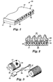
- Figure 1 is a perspective view of an enlarged fragment of a coated abrasive backing made by the method of the invention with edge surfaces revealing cross-sectional detail.
- Figure 2 is an enlarged fragmentary cross-sectional view of a coated abrasive article made by the method of the invention.
- Figure 3 is a perspective view of the major elements (without showing supporting structures) of an apparatus to practice a preferred process for making an endless spliceless reinforced backing structure according to the present invention.
- a reinforced spliceless backing 10 is made by the method of the invention.
- backing 10 comprises an endless spliceless backing loop substrate 11 to which is adherently bonded a fiber reinforcing layer 14 which comprises reinforcing fibers 15 which are saturated with binder 16.
- Binder 16 adheres fibers 15 within fiber reinforcing layer 14 and to backing substrate 11.
- Abrasive particles are then adhered by methods, such as described herein, to at least one of the exposed surfaces, front surface 17 or back surface 18, of backing 10, either on the side of fibers 15 or spliceless backing loop substrate 11.
- Binder 16 is applied to fibers 15 in a liquid or flowable state and solidified after fibers 15 are applied to backing substrate 11 by techniques described in greater detail hereinafter. Alternately, binder 16 may be applied to backing substrate 11 and then fibers 15 are applied over binder 16.
- the term “liquid” refers to a material that is flowable or flowing
- the term “solid” or “solidified” refers to a material that does not readily flow under ambient temperatures and pressures.
- the coated abrasive article a segment of which is shown, comprises a backing 20 having an endless spliceless backing loop substrate 21.
- reinforcing fibers 25 which are saturated with binder 26 are placed adjacent the backing substrate 21.
- a make coat 27 is first applied, then abrasive particles 28 are embedded therein.
- a size coat 29 is then applied over abrasive particles 28.
- Figure 2 depicts the abrasive coating on the side of the backing having the reinforcing fibers; although it is to be understood that the abrasive coating alternatively, and preferably, can be provided on the side of backing substrate 21 opposite to the reinforcing fibers.
- the length, width, and thickness of the reinforced backing can vary in dimension depending on the intended end use.
- the length of the coated abrasive belt (measured on the periphery of the belt) can be any desired length although typically the length is about 40-1000 centimeters (cm).
- the thickness of the endless spliceless reinforced backing 10 including spliceless backing loop substrate 11 and reinforcing fiber layer 14, is typically between about 0.07 millimeter (mm) and about 1 cm for optimum flexibility, strength, and material conservation. Further, the thickness of reinforced backing 10 preferably is consistent and uniform, i.e., it should not vary by more than about ⁇ 15% around the entire length of the backing 10, preferably not more than about ⁇ 5%. Although this variance refers to a variance along the thickness of the backing 10, it generally is reflected in coated abrasive material, i.e., the coated abrasive belt.
- a preferred method of insuring minimal variance of the backing material is to skive or lightly grind the exposed surface of binder layer 16 to provide a smooth, flat surface by removing any high spots which may eventually tend to reflect as imperfections in the final coated abrasive product.
- care should be taken not to grind so deeply as to weaken or damage reinforcing fibers or remove too much binder material or else the strength of the backing may be affected.
- Figure 3 illustrates key components of an apparatus used in the process for making a coated abrasive backing according to the method of the invention.
- the fiber reinforced backing of the invention is made on an apparatus 30.
- An endless spliceless backing loop substrate 31 is applied to a temporary support structure 36 which has a cylindrical surface which corresponds to the circumference of the desired reinforced backing.
- the circumference of the temporary support structure 36 e.g., drum 36
- the width is between about 15-100 cm.
- Reinforcing material in this case in the form of fibers 37, leave an unwind station 38 and are wetted with liquid binder precursor material at level winder station 39. These saturated fibers are then applied onto the spliceless backing loop substrate 31.
- the winding procedure involves the use of a strand guide system 40 with level winder 39.
- drum 36 is rotated (typically 25-75 rpm) while the reinforcing fibers 37 are initially attached to the spliceless backing loop substrate 31 (i.e., backing substrate 31) fitted to drum 36, and are pulled through the level winder 39, and are wound around the drum 36 helically or spirally across the width of the drum, such that the applied layer of the strand 41, upon completion of winding, is no wider than backing substrate 31.
- the spliceless backing loop substrate 31 i.e., backing substrate 31
- the level winder 39 move across the width of the drum such that the continuous reinforcing fibers 37 are uniformly applied in a layer across the width of the spliceless substrate 31.
- fiber 37 is in a helically wound pattern of a plurality of wraps in a layer within the organic polymeric binder material, with each wrap of the strand parallel to the previous wrap of the strand.
- the individual wraps of the fiber 37 are at a constant nonzero angle relative to the parallel side edges of the backing substrate 31.
- the reinforcing fibers are wound onto endless spliceless backing substrate 31 with a spacing of about 2-50 strands per cm of width: although it is to be understood that a broader range of strand spacing is contemplated within the scope of the invention.
- the spacing selected can depend on a number of variables, such as the strand material(s), reinforcing strength needed as a function of the type of backing material selected and type of service intended for the coated abrasive articles, among others.
- strands may be used to cover the entire width of the web backing in case that the strands have sufficient length to revolve more than once around the circumference of the backing web but are not sufficiently long to traverse the entire lateral width of the backing web.
- Sufficient uncured resin is applied to the backing substrate 31 to provide a layer of resin at least above and below the reinforcing fiber material therein, i.e., on the outer surfaces and sometimes even the interior of the reinforcing material.
- the binder precursor material not only can be applied to the fibers before winding, but, alternatively, it can be applied directly on backing substrate 31 after disposition on drum 36 and before winding over the backing substrate 31 over the previously wound strands, or in any combinations of these coating procedures to provide adhesion of the reinforcing fibers 37 to the backing substrate 31.
- the binder precursor used to coat the strands is exposed to an energy source (not shown), either thermal energy or radiation energy, to cure of polymerize the binder precursor. Further processing may then occur such as additional curing, flexing and/or humidification. After this optional further processing, the endless spliceless backing can be converted or slit into the desired form or shape in preparation for use as an abrasive article backing.
- an energy source not shown
- Further processing may then occur such as additional curing, flexing and/or humidification.
- the temporary support structure 36 used in such a method is preferably a drum, which can be made from a rigid material such as steel, metal, ceramic, a strong plastic material, or any combination thereof.
- the material of which the drum is made should have enough integrity such that repeated endless backings can be made without any damage to the drum.
- the drum is placed on a mandrel so that it can be rotated at a controlled rate by a motor. This rotation can range anywhere from 1 to 100 revolutions per minute (rpm) depending on the application.
- the drum is usually a rotatable one in the practice of the invention. Although, it is also contemplated that the drum could be nonrotatable where the strand applying means is capable of traveling around the circumference of the drum.
- the drum can be unitary or created of segments or pieces that collapse for easy removal of the endless, spliceless backing.
- the circumference of the drum will generally correspond to the inner length (circumference) of the endless, spliceless backing loop substrate.
- the width of the endless, spliceless backing loop substrate can be of any value less than the width of the drum.
- a single endless, spliceless backing can be made on the drum, removed from the drum, and the sides can be trimmed.
- the reinforced backing can be slit longitudinally into multiple reinforced backings with each having a width substantially less than the original backing.
- a release coating be applied to the periphery of the drum before the binder precursor or spliceless backing loop substrate or any of the other components are applied. This provides for easy release of the endless, spliceless backing after the binder is solidified. In most instances, this release coating will not become part of the endless, spliceless backing. If a collapsible drum is used in the preparation of a large endless, spliceless backing, such a release liner helps to prevent, or at least reduce, the formation of ridges in the inner surface of the reinforced backing, caused by seams or welds in the drum surface.
- release coatings include, but are not limited to, waxes, silicone waxes or fluorochemicals, or polymeric films coated with silicone waxes or fluorochemicals. It is also within the scope of this invention to use a second release coating which is placed over the final or top coating of the binder. This second release coating is typically present during the solidification of the binder, and can be removed afterwards.
- the reinforcing fiber layer can be applied to the spliceless backing loop substrate supported around two drum rollers, which are connected to a motor for driving at least one of rollers to rotate the backing.
- the backing can be installed around one drum roller, which is connected to a motor for rotating the backing.
- the adhesive layers or abrasive slurry are applied by any conventional coating technique such as knife coating, die coating, roll coating, spray coating, or curtain coating. Spray coating is preferred for certain applications.
- the resulting backing is removed from the temporary drum, optionally ground to remove any high spots, and then the abrasive coating is applied to either of the fiber reinforcing layer or the opposite side of the spliceless backing substrate.
- the fiber reinforced backing should be turned inside out (everted) to expose the opposite surface of the spliceless backing substrate, i.e., the side of the backing substrate opposite to the fiber reinforcing layer, if the abrasive coating is to be applied to that surface.
- the fiber reinforced backing is again temporarily supported on any convenient support means such as either a drum or at least two cantilevered idler rolls for application of an abrasive slurry or abrasive coating (sequential coating of make coat and abrasive particles).
- any convenient support means such as either a drum or at least two cantilevered idler rolls for application of an abrasive slurry or abrasive coating (sequential coating of make coat and abrasive particles).
- the abrasive grains can be electrostatically deposited onto the adhesive layer by an electrostatic coater.
- the drum roller acts as the ground plate for the electrostatic coater.
- the abrasive grains can be applied by mineral drop coating or magnetic coating.
- the make coat layer is solidified, or at least partially solidified, after embedding the abrasive particles, and then a size coat layer (and optionally a supersize coat) is applied.
- the size coat adhesive layer can be applied by any conventional method, such as roll coating, spray coating, or curtain coating.
- the size coat is preferably applied by spray coating.
- the make and size coats layer(s) can then be fully solidified while the backing is still on the drum rollers. Alternatively, the resulting product can be removed from the drum rollers prior to solidification of the adhesive layer(s).
- the coated abrasive articles of the present invention include a fiber reinforced backing with the following properties.
- the reinforced backing is sufficiently heat resistant under grinding conditions for which the abrasive article is intended to be used such that the backing does not significantly disintegrate, i.e., split, break, delaminate, tear, or a combination of these, as a result of the heat generated during a grinding, sanding, or polishing operation.
- the reinforced backing is also sufficiently tough such that it will not significantly crack or shatter from the forces encountered under grinding conditions for which the abrasive article is intended to be used. That is, it is sufficiently stiff to withstand typical grinding conditions encountered by coated abrasive belts, but not undesirably brittle.
- the reinforced backings, and spliceless endless coated abrasive belts incorporating same, of the present invention are sufficiently flexible to withstand grinding conditions.
- “sufficient flexibility” and variants thereof in this context it is meant that the reinforced backings, and spliceless endless coated abrasive belts, will flex or bend under typical grinding conditions and return to their original shape without significant permanent deformation.
- the reinforced backing (and the endless abrasive belt incorporating same) is capable of flexing and adapting to the contour of workpiece being abraded, yet is sufficiently strong to transmit an effective grinding force when pressed against the workpiece.
- Preferred reinforced backings of the present invention possess a generally uniform tensile strength in the longitudinal, i.e., machine direction. This is typically because the fibrous reinforcing material extends along the entire length of the backing and there is no seam in the continuous fibrous reinforcing material. More preferably, the tensile strength for any portion of a reinforced backing tested does not vary by more than about 20% from that of any other portion of the reinforced backing structure. Tensile strength is generally a measure of the maximum stress a material subjected to a stretching load can withstand without tearing.
- Preferred reinforced backings of the present invention also exhibit appropriate shape control and are sufficiently insensitive to environmental conditions, such as humidity and temperature.
- environmental conditions such as humidity and temperature.
- preferred reinforced backings of the present invention possess the above-listed properties under a wide range of environmental conditions.
- the reinforced backings possess the above-listed properties within a temperature range of about 10-30°C, and a humidity range of about 30-90% relative humidity (RH). More preferably, the reinforced backings possess the above-listed properties under a wide range of temperatures, i.e., from below 0°C to above 100°C, and a wide range of humidity values, from below 10% RH to 100% RH.
- the reinforced backings should also be able to withstand the grinding conditions and environments to which the coated abrasive article product is intended.
- the preferred backing substrate material used in coated abrasive backings of the present invention is generally chosen such that there will be compatibility with, and good adhesion to, the adhesive layers, particularly to the make coat. Good adhesion is determined by the amount of "shelling" of the abrasive material. Shelling is a term used in the abrasive industry to describe the undesired, premature release of a significant amount of the abrasive material from the backing. Although the choice of backing substrate material is important, the amount of shelling typically depends to a greater extent on the choice of adhesive and the compatibility of the backing substrate and adhesive layers and grinding conditions.
- the backing substrate is comprised of an endless, spliceless (tube-like) backing substrate.
- the backing substrate is then reinforced by continuously wound fibrous material, such as yarn, to provide the backing described herein.
- the endless spliceless backing loop substrate is generally selected from the group consisting of a woven cloth, a knitted cloth, paper, a nonwoven, including combinations and treated versions thereof.
- the preferred endless backing substrate is a cloth backing, either woven or knitted.
- materials useful as endless spliceless backing loop substrates in this invention include polyester, nylon, rayon, cotton, jute, and other materials know as cloth backings.
- the cloth is composed of yarns in the warp direction, i.e., the machine direction, and yarns in the fill direction, i.e. the cross direction.
- the cloth backing substrate can be a woven backing, a stitchbonded backing, or a weft insertion backing. Examples of woven constructions include sateen weaves of 4 over one weave of the warp yarns over the fill yearns; twill weave of 2 or 3 over one weave; plain weave of one over one weave; and a drill weave of two over two weave.
- the warp and fill yarns are not interwoven, but are oriented in two distinct directions from one another.
- the warp yarns are laid on top of the fill yarns and secured to another by a stitch yarn or by an adhesive.
- the endless spliceless backing is generally a tubular backing, meaning there can be found no appreciable beginning or end.
- Endless spliceless backing loop substrates are available from suppliers such as, for example, Advanced Belt Technology (of Middletown, CT) under the designations "WT3" and "WT4", and other various cloth manufacturers.
- the yarns in the cloth backing substrate can be natural, synthetic or combinations thereof.
- natural yarns include cellulosic yarns such as cotton, hemp, kapok, flax, sisal, jute, carbon, manila, and combinations thereof.
- synthetic yarns include polyester yarns, polypropylene yarns, glass yarns, polyvinyl alcohol yarns, polyimide yarns, aromatic polyamide yarns, rayon yarns, nylon yarns, polyethylene yarns and combinations thereof.
- the preferred yarns of this invention are polyester yarns, nylon yarns, a mixture of polyester and cotton, rayon yarns, and aromatic polyamide yarns.
- the cloth backing substrate can be dyed and/or stretched, desized, washed, or heat stretched. Additionally the yarns in the cloth backing can contain primers, dyes, pigments or wetting agents. The yarns can be twisted or textured.
- Polyester yarns are formed from a long chain polymer made from the reaction of an ester of dihydric alcohol and terephthalic acid; preferably this polymer is a linear polymer of poly(ethylene terephthalate).
- a ring spun yarn is made by continuously drafting a polyester yarn, twisting the yarn and winding the yarn on a bobbin.
- An open end yarn is made directly from a sliver or roving.
- a series of polyester rovings are opened and then all of the rovings are continuously brought together in a spinning apparatus to form a continuous yarn.
- a filament yarn is a long continuous fiber; a filament yarn typically has a very low or non-existent twist to the polyester fiber.
- the denier of the fibers should be less than about 5000, preferably between about 100 to 1500.
- the yarn size should range from about 1500 to 12,000 meters/kilogram.
- the weight of the greige cloth, i.e., the untreated cloth will range from about 0.15 to 1 kg/m 2 , preferably between about 0.15 to 0.75 kg/m 2 .
- the backing substrate is at least partially saturated with a saturant resin precursor providing a resin coat, and may also have a presize coat and/or a backsize coat.
- the purpose of these coats is to seal the backing substrate and/or protect the yarns or fibers in the backing substrate.
- the addition of the presize coat or backsize coat may additionally result in a "smoother" surface on either the front or back side of the backing substrate.
- the presize or backsize coat may penetrate through the entire thickness of the backing substrate, or may be applied so that the coating only penetrates half of the substrate thickness. The depth of penetration can be controlled by the viscosity of the various coatings. Viscosity can be altered, for example, by silica or clay additions.
- the resulting backing substrate can be heat treated or calendered.
- the heat treating can be done as the binder precursor is at least partially solidified by placing the backing substrate in a tenter frame which is in an oven. Additionally the backing substrate can be processed through heated hot cans. The calendering step will remove some surface roughness and typically increase the surface smoothness.
- latex resins examples include acrylonitrile butadiene emulsions, acrylic emulsions, butadiene emulsions, butadiene styrene emulsions and combinations thereof.
- These latex resins are commercially available under various tradenames from a variety of different sources including: “RHOPLEX” and “ACRYLSOL” commercially available from Rohm and Haas Company, “FLEXCRYL” and “VALTAC” commercially available from Air Products & Chemicals Inc., “SYNTHEMUL” and “TYLAC” commercially available from Reichold Chemical Co., “HYCAR” and “GOODRITE” commercially available from B.F. Goodrich, “CHEMIGUM” commercially available from Goodyear Tire and Rubber co., “NEOCRYL” commercially available from ICI, “BUTAFON” commercially available from BASF, and “RES” commercially available from Union Carbide.
- the backing substrate may additionally comprise other optional materials, such as additives selected from the group consisting of fillers, fibers, antistatic agents, lubricants, wetting agents, surfactants, pigments, dyes, coupling agents, plasticizers, and suspending agents, such as those described for backings in PCT Published Application No. WO 93/12911 published 8 July 1993 (Benedict et al.). The amounts of these materials are selected to provide the properties desired.
- additives selected from the group consisting of fillers, fibers, antistatic agents, lubricants, wetting agents, surfactants, pigments, dyes, coupling agents, plasticizers, and suspending agents, such as those described for backings in PCT Published Application No. WO 93/12911 published 8 July 1993 (Benedict et al.).
- additives selected from the group consisting of fillers, fibers, antistatic agents, lubricants, wetting agents, surfactants, pigments, dyes, coupling agents, plasticizers, and suspending agents,
- the fibrous reinforcing material used in the invention to reinforce the spliceless backing loop substrate preferably is in the form of individual fibrous strands.
- the material can be a narrow fibrous strip having a lateral width less than that of the backing substrate, such as in a preferred ratio of 1/100 to 10/100.
- Suitable fibrous strands for this invention are commercially available as threads, cords, yarns, rovings, and filaments. Threads and cords are typically assemblages of yarns. A thread has a very high degree of twist with a low friction surface. A cord can be assembled by braiding or twisting yarns and is generally larger than a thread. A yarn is a plurality of fibers or filaments either twisted together or entangled. A roving is a plurality of fibers or filaments pulled together either without a twist or with minimal twist. A filament is a continuous fiber. Both roving and yarns are composed on individual filaments. A fiber mat or web consists of a matrix of fibers, i.e., fine thread like pieces with an aspect ration of at least about 100:1. The aspect ratio of a fiber is the ratio of the longer dimension of the fiber to the shorter dimension.
- the fibrous reinforcing material can be composed of any material that increases the strength of the backing and/or prevents stretch.
- useful reinforcing fibrous material in applications of the present invention include metallic or nonmetallic fibrous material, with the preferred being nonmetallic.
- the nonmetallic fibrous materials may be materials made of glass including "FIBERGLAS", carbon minerals, synthetic or natural heat resistant organic reinforcing materials, or ceramic materials.
- Preferred fibrous reinforcing materials for the present invention are organic materials, glass, and ceramic fibrous material.
- Useful natural organic fibrous materials include wool, silk, cotton, or cellulose.
- Examples of useful synthetic organic fibrous materials are made from polyvinyl alcohol, nylon, polypropylene, polyester, rayon, polyamide, acrylic, polyolefin, aramid, or phenol.
- the preferred organic fibrous material for applications of the present invention is aramid fibrous material; such a material is commercially available from DuPont Co. under the trade names of "KEVLAR” and "NOMEX”. It is also possible to have more than one type of reinforcing fiber in the backing construction.
- any ceramic fibrous reinforcing material is useful in applications of the present invention.
- An example of a ceramic fibrous reinforcing material suitable for the present invention is "NEXTEL" is commercially available from The 3M Company.
- Fibers such as "FIBERGLAS” and nylon, or “FIBERGLAS” and polyester, or aramid and nylon, or aramid and polyester, can be used in combination as the types of strand material by alternate winding of each type across the width of the preformed spliceless backing, either in the same winding direction or in a criss-cross type winding.
- the different fibers used should be chosen for their desirable properties, such as low stretch for fiberglass and high strength for nylon.
- the reinforcing fibers may contain a pretreatment of some kind, prior to being incorporated into the backing. This pretreatment may be an adhesion promoter or a slashing compound.
- the fiberglass reinforcing fibers may contain a surface treatment, such as an epoxy or urethane compatible fiberglass yarn to promote adhesion to the make coat. Examples of such fiberglass yarns are "930" fiberglass yarns from PPG, Pittsburgh, PA, and "603" fiberglass yarns from Owens-Corning. Useful grades of such glass yarns and rovings are in the range of about 150 to 32,000 meters/kg, which are also preferred.
- the glass fibrous material be accompanied by an interfacial binding agent, i.e., a coupling agent, such as a silane coupling agent, to improve adhesion to the organic binder material, particularly if a thermoplastic binder material is used.
- a coupling agent such as a silane coupling agent
- the fibrous reinforcing material is of a length sufficient to extend around the length, i.e., circumference, of the coated abrasive loop a plurality of times and provide at least one distinct layer of fibrous reinforcing material.
- the fibrous reinforcing material is of a length sufficient to place the strand in a helically wound pattern of a plurality of wraps in a layer within the organic polymeric binder material, with each wrap of the strand parallel to and in contact with the previous wrap of the strand. This helix generally and preferably extends longitudinally along the entire length of the backing loop.
- each wrap of the strand approaches a parallel position relative to the side edges of the loop, although no individual wrap exactly parallels the side edges. Rather, the wraps are preferably at a constant, substantially nonzero angle relative to the parallel side edges of the spliceless backing substrate or web.
- the reinforcing fiber denier i.e., degree of fineness, for preferred fibrous reinforcing material ranges from about 5 to about 5000 denier, typically between about 50 and about 2000 denier. More preferably, the fiber denier will be between about 100 and about 1500. It is understood that the denier is strongly influenced by the particular type of fibrous reinforcing material employed.
- the backing spliceless backing loop substrate/reinforcing layer
- fibrous reinforcing material there are provided distinct regions of the backing (spliceless backing loop substrate/reinforcing layer) that do not have fibrous reinforcing material therein.
- one area of the backing having a greater ratio of fibrous reinforcing material to organic polymeric binder material than another area.
- the fibrous reinforcing material can be entirely located within a region in the lateral sides and/or the central area of the backing layer such that some outer edges thereof would be substantially uncovered by fibrous reinforcing material.
- This embodiment may not be acceptable in all cases as it may create an uneven surface on the backing.
- the fibrous reinforcing material is applied onto the spliceless backing loop substrate which is temporarily held on a support structure described herein, such as a drum structure.
- the binder precursor can be applied first to the spliceless backing loop substrate, followed by winding of the reinforcing material.
- the reinforcing material can be applied first to the spliceless backing loop substrate, followed by the binder precursor.
- the reinforcing material can be first saturated with the binder precursor and then applied to the spliceless backing loop substrate.
- the binder precursor can be applied sequentially or simultaneously with the reinforcing material. It is also within the scope of this invention to use a combination of any of these three previous methods.
- a nonwoven substrate in combination with the reinforcing fibers.
- the nonwoven substrate in some instances, can increase the tear strength of the resulting backing. It is contemplated for instance, that a nonwoven substrate is first saturated with a first binder precursor and applied over the second surface of the backing substrate. Next, the reinforcing yarns are applied on top of the saturated nonwoven substrate. The first binder precursor will wet the reinforcing yarns and bond the reinforcing yarns to the backing substrate.
- the reinforcing fibers are applied to an endless spliceless backing loop substrate already containing an abrasive coating.
- the backing substrate is turned inside out, i.e., the abrasive coating faces the support drum and the reinforcing fibers are applied to the backing substrate surface opposite the abrasive coating.
- the resulting endless belt is essentially turned inside out to form the endless coated abrasive article.
- the resulting endless abrasive belt article of the invention comprises a backing having a spliceless backing loop substrate and a plurality of reinforcing fibers continuously present over the surface area. It is generally preferred that the reinforcing fibers be parallel and non-interlacing as applied upon the backing substrate. It is also within the scope of this invention that the reinforcing fibers are continuous over the entire lateral width of the spliceless backing loop substrate, i.e., there is no substantial break or gap in the spacing of the reinforcing fibers across the width of the backing substrate. It is understood that the reinforcing fiber will have a starting end and a tail end with the intervening length of the fiber continuous in at least more than one revolution around the spliceless backing loop substrate.
- thermoplastic and thermoelastic beads extruded and cooled in-situ as helical windings over the spliceless backing substrate are also contemplated.
- the binder precursor material used for securing the fibrous reinforcing material strands or narrow strips can be selected from a wide variety of binder materials which can be applied in liquid form and later solidified.
- the amount of binder precursor, which is an organic polymeric binder material, used to saturate the reinforcing fibers is within a range of about 40-99 wt%, more preferably within a range of about 65-92 wt%, and most preferably within a range of about 70-85 wt%, based on the total weight of the fiber reinforcing layer alone.
- the binder material used to secure the reinforcing material in the fiber reinforcing layer is an organic polymeric binder material. It can be a cured or solidified thermosetting resin, thermoplastic material, or elastomeric material. Preferably, the organic polymeric binder material is a cured or solidified thermosetting resin. It is preferred that the binder material is a thermosetting resin, at least because such resins can be provided in a very fluid (low viscosity) flowable form when uncured, even under ambient conditions.
- ambient conditions and variants thereof refer to room temperature, i.e., 15-30°C, generally about 20-25°C, and 30-50% relative humidity, generally about 35-45% relative humidity.
- the thermosetting resin prior to the manufacture of the backing, such as for wetting the reinforcing fibers 15 and/or for impregnating a cloth backing web 11 with a binder precursor, the thermosetting resin is in a nonpolymerized state, typically in a liquid or semiliquid state. During the manufacturing process, the thermosetting resin is cured or polymerized to a solid state. Depending upon the particular thermosetting resin employed, the thermosetting resin can use a curing agent or catalyst. When this curing agent is exposed to an appropriate energy source (such as thermal energy or radiation energy) the curing agent will initiate the polymerization of the thermosetting resin.
- an appropriate energy source such as thermal energy or radiation energy
- thermosetting resins from which the backing can be prepared include phenolic resins, amino resins, polyester resins, aminoplast resins, urethane resins, melamine-formaldehyde resins, epoxy resins, acrylated isocyanurate resins, urea-formaldehyde resins, acrylate resins and mixtures of isocyanurate resins, acrylated urethane resins, acrylated epoxy resins, or mixtures thereof.
- the preferred thermosetting resins are urethane resins, acrylate resins, epoxy resins, acrylated urethane resins, polyester resins, or flexible phenolic resins, and mixtures thereof.
- the most preferred resins are urethane resins, acrylate resins, epoxy resins, acrylated urethane resins, and mixtures thereof, because they exhibit an acceptable cure rate, flexibility, good thermal stability, strength, and water resistance.
- polyurethane elastomer in particular a polyether based polyurethane.
- polyurethane materials are commercially available from Uniroyal Chemical under the trade designation "VIBRATHANE” and "ADIPRENE”.
- VIBRATHANE toluene diioscyanate terminated prepolymer
- ADIPRENE ADIPRENE
- prepolymers can be crosslinked with 4,4'-methylene-bis-(ortho-chloroaniline) or a diamine curative.
- polyurethane binders are also preferred, because during thermal curing the polyurethane resins do not appreciably reduce their viscosity and thus do not appreciably flow during curing. It is also within the scope of this invention to blend polyurethane resins with epoxy resins and acrylate resins.
- Phenolic resins are usually categorized as resole or novolac phenolic resins. Examples of useful commercially available phenolic resins are "VARCUM” from BTL Specialty Resins Corporation; “AROFENE” from Ashland Chemical Company; “BAKELITE” from Union Carbide; and “RESINOX” from Monsanto Chemical Company.
- Resole phenolic resins are characterized by being alkaline catalyzed and having a molar ratio of formaldehyde to phenol of greater than or equal to 1:1. Typically, the ratio of formaldehyde to phenol is within a range of about 1:1 to about 3:1.
- alkaline catalysts useable to prepare resole phenolic resins include sodium hydroxide, potassium hydroxide, organic amines, or sodium carbonate.
- Novolac phenolic resins are characterized by being acid catalyzed and having a molar ratio of formaldehyde to phenol of less than 1:1. Typically, the ratio of formaldehyde to phenol is within a range of about 0.5:1 to about 0.8:1.
- the acid catalysts used to prepare novolac phenolic resins include sulfuric, hydrochloric, phosphoric, oxalic, or p-toluenesulfonic acids.
- novolac phenolic resins are typically considered to be thermoplastic resins rather than thermosetting resins, they can react with other chemicals (e.g., hexamethylenetetraamine) to form a cured thermosetting resin.
- Epoxy resins useful in the polymerizable mixture used to prepare backings of this invention include monomeric or polymeric epoxides.
- Useful epoxy materials i.e., epoxides, can vary greatly in the nature of their backbones and substituent groups.
- Representative examples of acceptable substituent groups include halogens, ester groups, ether groups, sulfonate groups, siloxane groups, nitro groups, or phosphate groups.
- the weight average molecular weight of the epoxy-containing polymeric materials can vary from about 60 to about 4000, and are preferably within a range of about 100 to about 600. Mixtures of various epoxy-containing materials can be used in the compositions of this invention. Examples of commercially available epoxy resins include "EPON" from Shell Chemical Co.; and "DER” from Dow Chemical Company.
- urea-formaldehyde resins examples include “UFORMITE” from Reichold Chemical, Inc.; “DURITE” from Borden Chemical Co.; and “RESIMENE” from Monsanto.
- melamine-formaldehyde resins examples include “UFORMITE” from Reichhold Chemical, Inc. NC; and “RESIMENE” from Monsanto. "RESIMENE” is used to refer to both urea-formaldehyde and melamine-formaldehyde resins.
- aminoplast resins useful in applications according to the present invention are those having at least one pendant alpha, beta-unsaturated carbonyl groups per molecule, which are disclosed, for example, in U.S. Patent Nos. 4,903,440 (Larson et al.) and 5,236,472 (Kirk et al.).
- Useable acrylated isocyanurate resins are those prepared from a mixture of: at least one monomer selected from the group consisting of isocyanurate derivatives having at least one terminal or pendant acrylate group and isocyanate derivatives having at least one terminal or pendant acrylate group; and at least one aliphatic or cycloaliphatic monomer having at least one terminal or pendant acrylate group.
- acrylated isocyanurate resins are described, for example, in U.S. Patent No. 4,652,274 (Boettcher et al.).
- Ethylenically unsaturated resins include both monomeric and polymeric compounds that contain atoms of carbon, hydrogen and oxygen, and optionally, nitrogen and the halogens. Oxygen or nitrogen atoms or both are generally present in ether, ester, urethane, amide, and urea groups. Ethylenically unsaturated compounds preferably have a molecular weight of less than about 4,000 and are preferably esters made from the reaction of compounds containing aliphatic monohydroxy groups or aliphatic polyhydroxy groups and unsaturated carboxylic acids, such as acrylic acid, methacrylic acid, itaconic acid, crotonic acid, isocrotonic acid, maleic acid, and the like.
- acrylate resins include methyl methacrylate, ethyl methacrylate styrene, divinylbenzene, vinyl toluene, ethylene glycol diacrylate, ethylene glycol methacrylate, hexanediol diacrylate, triethylene glycol diacrylate, propyleneglycol diacrylate, trimethylolpropane triacrylate, glycerol triacrylate pentaerythritol triacrylate, pentaerythritol methacrylate, tetraacrylate.
- ethylenically unsaturated resins include monoallyl, polyallyl, and polymethallyl esters and diallyl adipate, and N,N-diallyladipamide.
- Still other nitrogen containing compounds include tris(2-acryloyl-oxyethyl) isocyanurate, 1,3,5-tri(2-methylacryloxyethyl)-s-triazine, acrylamide, methlacrylamide, N-methylacrylamide, N-N-dimethylacrylamide, N-vinylpyrrolidone, and N-vinylpiperidone.
- Acrylate urethanes are diacrylate esters of hydroxy terminated NCO extended polyesters or polyethers.
- Examples of commercially available acrylated urethanes include "UVITHANE 782", available from Morton Thiokol Chemical, and "CMD 6600”, “CMD 8400”. and “CMD 8805”, available from Radcure Specialties.
- the acrylated epoxies are diacrylate esters, such as the diacrylate esters of bisphenol A epoxy resin.
- Examples of commercially available acrylated epoxies include those having the trade names "EBECRYL 3500”, “EBECRYL 3600”, and “EBECRYL 8805", available from Radcure Specialties.
- thermosetting polyester resins are available as “E-737” or “E-650” from Owens-Corning Fiberglass Corp.
- Suitable polyurethanes also are available as “VIBRATHANE” B-813 prepolymer or “ADIPRENE” BL-16 prepolymer used with “CAYTUR”-31 curative. All are available from Uniroyal Chemical.
- thermoplastic binder material can be used to bond the reinforcing fibers wound to the backing substrate, as opposed to the preferred thermosetting resins discussed above.
- a thermoplastic binder material is a polymeric material that softens when exposed to elevated temperatures and generally returns to its original physical state when cooled to ambient temperatures. During the manufacturing process, the thermoplastic binder is heated above its softening temperature, and often above its melting temperature, to be in a flowable state. After the reinforced fibers are bonded to the backing substrate, the thermoplastic binder is cooled and solidified.
- thermoplastic materials of the invention are those having a high melting temperature and/or good heat resistant properties. That is, preferred thermoplastic materials have a melting point of at least about 100°C, preferably at least about 150°C. Additionally, the melting point of the preferred thermoplastic materials is sufficiently lower, i.e., at least about 25°C lower, than the melting temperature of the reinforcing material. In this way, the reinforcing material is not adversely effected during the melting process of the thermoplastic binder.
- thermoplastic materials suitable for preparations of backings in articles according to the present invention include polycarbonates, polyetherimides, polyesters, polysulfones, polystyrenes, acrylonitrilebutadiene-styrene block copolymers, polypropylenes, acetal polymers, polyamides, polyvinyl chlorides, polyethylenes, polyurethanes, or combinations thereof. Of this list, polyamides, polyurethanes, and polyvinyl chlorides are preferred, with polyurethanes and polyvinyl chlorides being most preferred.
- thermoplastic material from which the backing is formed is a polycarbonate, polyetherimide, polyester, polysulfone, or polystyrene material
- a primer can be used to enhance the adhesion between the fiber reinforcing layer and the make coat, if the make coat is chosen to be applied on that side of the backing.
- primer is meant to include both mechanical and chemical type primers or priming processes. This is not meant to include a layer of cloth or fabric attached to the surface of the backing.
- mechanical primers include, but are not limited to, corona treatment and scuffing, both of which increase the surface area of the surface.
- An example of a chemical primer is a colloidal dispersion of, for example, polyurethane, acetone, a colloidal oxide of silicon, isopropanol, and water, as disclosed, for example, by U.S. Patent No. 4,906,523 (Bilkadi et al.).
- priming of a surface can involve scuffing, i.e., roughening up to increase the surface area of the surface
- the surface of the backing is still relatively "smooth" as defined above. That is, the surface topology is generally smooth and flat such that there is little, if any, exposed, i.e., protruding, fibrous reinforcing material.
- the surface topology is generally not effected by the fibrous reinforcing material within the organic polymeric binder material such that it would mirror the underlying topology of the fibrous reinforcing material.
- a third type of binder useful in the saturating the reinforcing fibers of the present invention is an elastomeric material.
- An elastomeric material i.e., elastomer, is defined as a material that can be stretched to at least twice its original length and then retract very rapidly to approximately its original length, when released.
- Examples of elastomeric materials useful in applications of the present invention include styrene-butadiene copolymers, polychloroprene (neoprene), nitrile rubber, butyl rubber, polysulfide rubber, bis-1,4-polyisoprene, ethylenepropylene terpolymers, silicon rubber, or polyurethane rubber.
- the elastomeric materials can be crosslinked with sulfur, peroxides, or similar curing agents to form cured thermosetting resins.
- a preferred viscosity range is between about 500 to 20,000 centipoise, more preferably between 1,000 and 15,000 and most preferred between 2,000 to 10,000 centipoises. These viscosity measurements are taken at room temperature. The viscosity may be adjusted by the amount of solvent (the % solids of the resin) and/or the chemistry of the starting resin.
- Heat may additionally be applied during the applying of the reinforcing strands to the spliceless backing substrate on the temporary support to effect better wetting of the binder precursor onto the reinforcing fibers.
- the amount of heat should be controlled such that there is not premature solidification of the binder precursor.
- the binder preferably should substantially engulf or encase the reinforcing fibers.
- the binder precursor will wet the majority of the reinforcing fibers, however there may be a minor, preferably a very minor amount of reinforcing fibers that are not engulfed by the binder precursor.
- the term "sufficient" means that there is enough binder precursor to provide an abrasive backing that has the desired properties for the intended application. These properties include tensile strength, heat resistance, tear resistance, stretch, and the like. There may be sufficient binder within a backing, and still have some internal porosity.
- the binder will typically seal the back side of the backing to provide an continuous layer or coating on the back side of the spliceless backing substrate.
- the term seal means that a liquid, such as water, cannot penetrate into the backing through the back side of the backing.
- the binder precursor is solidified by exposure to an energy source, such as thermal energy or radiation energy.
- the fiber reinforced backing structure can be rotated on the drum during thermal curing. This rotation can minimize the binder precursor from flowing during its curing to form a nonsmooth contour, and thus ultimately minimizes the shifting of abrasive particles if later applied to the fiber reinforcing layer during a curing of a make coat.
- One preferred method of making the reinforced backing structure of the invention is to first provide an endless spliceless backing loop substrate which has the length of the final desired belt length; this backing is then removably applied to a support structure or drum. Alternating yarns or strands of nylon and fiberglass then are applied over the spliceless backing substrate by winding techniques described hereinabove. Alternatively, the two different types of fibers can be polyester and aramid. As the yarns are applied, the tension should be set such that the yarns are pulled down onto the spliceless backing substrate. This tension will also help promote wetting of the binder precursor onto the reinforcing yarns. There is sufficient binder precursor used to at least wet the reinforcing yarns before, during or after their application to the surface of the backing substrate.
- the fibrous reinforcing material is applied in two wound layers, these two layers having windings which cross in inclination. It is preferred that after the first winding is applied, the binder precursor is at least partially cured before a second winding (including additional binder precursor) is applied.
- garnet, silica, polymer particles, or coke particles, and the like can be dispersed, such as by electrostatic coating, slurry coating, drop coating, or spray coating, in a resin akin to that used to wet the fibrous reinforcing strands.
- This dispersion can be coated onto either the exposed side of the backing substrate or the fiber reinforcing layer, whichever side is opposite to the side ultimately bearing the abrasive coating, to impart texture to provide a frictional grip coat or traction coat.
- This traction coat can facilitate the driving of the belt.
- the traction coat also could be formed of a binder precursor with mineral particles or fibers dispersed therein, or woven or nonwoven webs.
- the reinforced backing structure comprising a spliceless backing loop substrate and the fibrous reinforcing material applied thereover as described herein, is then used as a coated abrasive backing.
- the abrasive material can be applied by any known means, i.e., drop coating, slurry coating, electrostatic coating, roll coating, etc.
- the abrasive coating is preferably applied to the side of the backing having the spliceless conventional backing due to the increased adhesion to the conventional backing over the fibers.
- abrasive particles and several adhesive layers which are typically also applied in binder precursor form, is contemplated in the context of forming the abrasive coating surface of the article.
- a make coat, or second adhesive layer can be applied to either side of the backing, the spliceless backing substrate side or the reinforcing fiber layer side, however the spliceless backing substrate side is preferred.
- the make coat binder precursor can be coated by any conventional technique, such as knife coating, spray coating, roll coating, rotogravure coating, and the like.
- composition of the adhesive layers which relate to the make coat and the size and supersize coats mentioned below, can be the following materials.
- the adhesive layers in the coated abrasive articles of the present invention used variously as make, size and supersize coats typically are formed from a resinous adhesive.
- Each of the layers can be formed from the same or different resinous adhesives.
- Useful resinous adhesives are those that are compatible with the organic polymeric binder material of the backing. Cured resinous adhesives are also tolerant of grinding conditions such that the adhesive layers do not deteriorate and prematurely release the abrasive material.
- the resinous adhesive is preferably a layer of a thermosetting resin.
- thermosetting resinous adhesives suitable for this invention include, without limitation, phenolic resins, aminoplast resins, urethane resins, epoxy resins, acrylate resins, acrylated isocyanurate resins, urea-formaldehyde resins, isocyanurate resins, acrylated urethane resins, acrylated epoxy resins, or mixtures thereof.
- the thermosetting resin adhesive layers contain a phenolic resin, an aminoplast resin, or combinations thereof.
- the phenolic resin is preferably a resole phenolic resin.
- examples of commercially available phenolic resins include "VARCUM” from OXY Chem Corporation, Dallas, TX; "AROFENE” from Ashland Chemical Company, Columbus, OH; and "BAKELITE” from Union Carbide, Danbury, CT.
- a preferred aminoplast resin is one having at least one pendant alpha, beta-unsaturated carbonyl groups per molecule, which is made according to the disclosure of U.S. Patent No. 4,903,440 (Larson et al.) or 5,236,472 (Kirk et al.).
- the make and size coats, layers 27 and 29 respectively in Figure 2 can preferably contain other materials that are commonly utilized in abrasive articles. These materials, referred to as additives, include grinding aids, fillers, coupling agents, wetting agents, dyes, pigments, plasticizers, release agents, or combinations thereof. One would not typically use more of these materials than needed for desired results. Fillers are typically present in no more than an amount of about 90 wt%, for either the make or size coat, based upon the weight of the adhesive. Examples of useful fillers include calcium salts, such as calcium carbonate and calcium metasilicate, silica, metals, carbon, or glass.
- the adhesive layers are formed from a calcium metasilicate filled resin treated with a silane coupling agent, such as resole phenolic resin, for example.
- a silane coupling agent such as resole phenolic resin
- Resole phenolic resins are preferred at least because of their heat tolerance, toughness, high hardness, and low cost.
- the adhesive layers include about 50-90 wt% silane treated calcium metasilicate in a resole phenolic resin.
- the abrasive particles suitable for this invention include fused aluminum oxide, heat treated aluminum oxide, ceramic aluminum oxide, silicon carbide, alumina zirconia, garnet, diamond, cubic boron nitride, titanium diboride, or mixtures thereof.
- the abrasive particles can be either shaped (e.g., rod, triangle, or pyramid) or unshaped (i.e., irregular).
- the term "abrasive particle” encompasses abrasive grains, agglomerates, or multi-grain abrasive granules. Examples of such agglomerates are described in U.S. Patent No. 4,652,275 (Bloecher et al.) and U.S. Application No.
- the agglomerates can be irregularly shaped or have a precise shape associated with them, for example, a cube, pyramid, truncated pyramid, or a sphere.
- An agglomerate comprises abrasive particles or grains and a bonding agent.
- the bonding agent can be organic or inorganic.
- organic binders include phenolic resins, urea-formaldehyde resins, and epoxy resins.
- Example of inorganic binders include metals (such as nickel), and metal oxides. Metal oxides are usually classified as either a glass (vitrified), ceramic (crystalline), or glass-ceramic. Further information on ceramic agglomerates is disclosed in U.S. Application No. 08/316,259 (Christianson) filed 30 September 1994, assigned to the assignee of the present invention.
- Useful aluminum oxide grains for applications of the present invention include fused aluminum oxides, heat treated aluminum oxides, and ceramic aluminum oxides. Examples of such ceramic aluminum oxides are disclosed in U.S. Patent Nos. 4,314,827 (Leitheiser et al.), 4,744,802 (Schwabel), 4,770,671 (Monroe et al.), and 4,881,951 (Wood et al.).
- the average particle size of the abrasive particle for advantageous applications of the present invention is at least about 0.1 micrometers, preferably at least about 100 micrometers.
- a grain size of about 100 micrometers corresponds approximately to a coated abrasive grade 120 abrasive grain, according to American National Standards Institute (ANSI) Standard B74.18-1984.
- the abrasive grain can be oriented, or it can be applied to the backing without orientation, depending upon the desired end use of the coated abrasive backing.
- the abrasive particles can be embedded into the make coat precursor by any conventional technique such as electrostatic coating, drop coating, or magnetic coating.
- electrostatic coating electrostatic charges are applied to the abrasive particles and this propels the abrasive particles upward. Electrostatic coating tends to orient the abrasive particle, which generally leads to better abrading performance.
- drop coating the abrasive particles are forced from a feed station and fall into the binder precursor by gravity. It is also within the scope of this invention to propel the abrasive particles upward by a mechanical force into the binder precursor.
- Magnetic coating involves using magnetic forces to coat the abrasive particles.
- the backing be placed on a drum.
- This drum can be the original support structure or a different drum.
- the drum serves as a ground for the electrostatic coating process.
- the proper amount of abrasive particles is then placed on a plate underneath the drum.
- the drum is rotated and the electrostatic field is turned on.
- the abrasive particles are embedded into the make coat.
- the drum is rotated until the desired amount of abrasive particles is coated.
- the resulting construction is exposed to conditions sufficient to solidify the make coat.
- a charged plate can be used as the ground for the electrostatic process instead of the drum.
- a size coat, or third adhesive layer may be applied over the abrasive particles and the make coat such as by roll coating or spray coating.
- the preferred size coat is a resole phenolic resin filled with a silane treated calcium metasilicate. After the size coat is applied, the size coat is solidified, typically upon exposure to an energy source. These energy sources include both thermal and radiation energy.
- the optional supersize coat can preferably include a grinding aid, to enhance the abrading characteristics of the coated abrasive.
- grinding aids include potassium tetrafluoroborate, cryolite, ammonium cryolite, or sulfur. One would not typically use more of a grinding aid than needed for desired results.
- the supersize coat may comprise a binder and a grinding aid.
- the abrasive material can also be applied using a preformed abrasive coated laminate.
- This laminate consists of a substrate of material coated with abrasive grains.
- the substrate of material can be a piece of cloth, polymeric film, vulcanized fiber paper, and the like.
- the laminate can be applied to the outer surface of the backing of the present invention using; any of the adhesives discussed above; thermobonding; a pressure sensitive adhesive; or mechanical fastening means, such as a hook and loop means, such as disclosed, for example, in U.S. Patent No. 4,609,581 (Ott).
- This embodiment of the coated abrasive article of the present invention is advantageous at least because of the potential for removing the laminate once the abrasive material is exhausted and replacing it with another such laminate. In this way the backing of the present invention can be recycled and reused.
- the weave was a 2 cotton over 1 polyester weave, with cotton in the warp (machine) direction and polyester in the weft (fill) direction.
- the polyester was about 11 threads/cm, and the cotton was about 45 threads/cm.
- the polyester was in belt circumference and the cotton was in the cross direction.
- the length of the spliceless backing was 335.3 cm (132 inches) and the width was 30.5 cm (12 inches).
- the spliceless backing loop substrate was rinsed in tap water and placed over an aluminum hub which had a circumference of 335.3 cm, a width of 38.1 cm, and a wall thickness of 0.64 cm.
- the hub was installed on a 7.6 cm mandrel that rotated by a DC motor and was capable of rotating from 1 to 45 revolutions per minute (rpms).
- a backing saturant was applied to the spliceless backing once it was on the hub.
- a layer of resin having the following formulation, was coated onto the spliceless backing loop substrate: 25 parts DW, 0.5 part SCA, 14 parts ASC, 21.5 parts RPR, 2.5 parts ASF, 36 parts HLR, 0.25 part SWA1, and 0.25 part SWA2.
- the viscosity of this saturant resin was 310 cps when measured at 34° C with a Brookfield Viscometer, spindle 2, at 60 rpm.
- the wet weight of the saturant coating was approximately 0.0325 gram per square cm (0.21 gram per inch) and soaked approximately half the thickness of the backing loop. After coating, the drum was rotated at 3 rpm and the saturant coating was dried and partially cured using infrared heaters.
- An epoxy resin coating referred to as a "pre-size", having the following formulation, was coated onto the saturated spliceless backing: 73 parts ERH, 24.35 parts POPDA, 2.4 parts ASF, and 0.25 part SWA2.
- the wet weight of this epoxy coating was approximately 0.009 gram per square cm (0.06 gram per square inch). After coating, the drum was rotated at 3 rpm and the coating was partially cured using the infrared heaters as above.
- a urethane resin formulation known as the "winding" resin, having the following formulation, was coated onto the cured pre-size coating to form a "base layer": 50 parts UR1, 23 parts DMTA, 26 parts TPGA, 0.5 part PH2, and 0.5 part SWA2.
- the wet weight of this coating was approximately 0.0325 gram per square cm (0.21 gram per square inch).
- a doctor blade was used to smooth the winding resin.
- the smoothed resin then cured for 60 seconds with a (600 watt/inch) "V" bulb from Fusion Systems.
- a second layer of winding resin was coated on top of the cured base layer, by the methods described above.
- 800 denier "KEVLAR 49" fiber available from Synthetic Thread Co. Inc., Bethlehem, PA, was wound onto and into the smoothed resin at about 16.5 threads per cm (42 threads per inch) of belt width.
- the fibers were essentially engulfed by the resin.
- the "KEVLAR" fibers strengthen the final backing and minimize stretch.
- the strands were first run through a tensioner and then wound through a comb, two at a time.
- the reinforcing fibrous strands were wrapped over the spliceless backing loop substrate by means of a yarn guide system with a level winder that moved across the face of the hub at a rate of 10 cm per minute. During this process, the hub rotated at 45 rpm. After wrapping, the resin and fibers were smoothed with a doctor blade, and cured for 60 seconds with the same "V" lamp.
- the fiber reinforced backing structure was removed from the hub and turned inside out, i.e. everted, so that the reinforcing fibers were located on the inside of the loop.
- Example 2 was prepared in the same manner as Example 1, except that after the layers of winding resin were coated and cured, approximately 0.12-0.25 mm (5-10 mils) of cured resin was ground off with a Doall D-10 grinder (The Doall Company, Des Plaines, IL) using 180 micron Imperial Microfinishing Film (from Minnesota Mining and Manufacturing Co.). This act of grinding the back aided in smoothing the backing further and providing an even caliper.
- Doall D-10 grinder The Doall Company, Des Plaines, IL
- 180 micron Imperial Microfinishing Film from Minnesota Mining and Manufacturing Co.
- Example 3 was prepared in the same manner as Example 1, except that after applying and smoothing the second layer of winding resin, a third layer of winding resin was coated and smoothed. A second layer of fiber was wound into and onto the smoothed resin. The resin was cured, and a fourth layer of resin was coated and cured. The resulting belt was everted.
- Example 4 was prepared in the same manner as Example 3, except that after the final cure, the belt was removed from the hub, and slit to 7.62 cm (3 inches). These slit strips were moved to a mandrel (reinforcing fibers out), and approximately 0.12-0.25 mm (5-10 mils) of cured resin was ground off with a Doall D-10 grinder using 180 micron Imperial Microfinishing Film (from Minnesota Mining and Manufacturing Co.). This act of grinding the back aided in smoothing the backing further and providing an even caliper.
- Example 5 was a coated abrasive belt made using the backing of Example 1 which had been slit to 7.6 cm (3 inches).
- the fiber reinforced backing structure, Example 1 was turned inside out, i.e., everted, so that the reinforcing fibers were on the inside, and placed under tension on a pair of idler rolls with one roll drivable by motor to rotate the backing. All resin coatings were on the polyester/cotton side of the backing.
- a saturant resin having the following formulation, was roll coated on the exposed side of spliceless backing substrate opposite the fiber reinforcing layer: 31.6 parts DW, 0.4 part SCA, 13.3 parts ASC, 20 parts RPR, 1.8 parts ASF, 32.4 parts HLR, 0.25 part SWA1, and 0.25 part SWA2.
- the wet weight of this saturant coating was approximately 0.019 grams per square cm (0.12 gram per square inch).
- the saturated backing was placed on a round hub and dried in an oven for 30 minutes at 90°C.
- An epoxy pre-size resin having the following formulation, was knife coated onto the dried backing: 73 parts ERH, 24.35 parts POPDA, 2.4 parts ASF, and 0.25 part SWA2.
- the wet weight of this size coating was approximately 0.011 grams per square cm (0.07 gram per square inch).
- the coated backing was placed on a round hub and cured in an oven for 30 minutes at 90°C.
- a phenolic make resin having the following formulation, was knife coated in a 5.7 cm (2.25 inch) wide path on the 7.6 cm (3 inch) wide backing: 34.29 parts RPR, 12.46 parts DW, 51.85 parts CMSK, 0.75 part ASF, 0.19 part ASC, 0.23 part SWA1, and 0.23 part SWA2.
- the knife setting (gap) was set at 0.3 mm (0.013 inch).
- Vitrified agglomerates were prepared according to the method described below.
- a glass binder, GPM was formulated so that its coefficient of thermal expansion was approximately the same as the coefficient of thermal expansion of the superabrasive grains used in the examples (3.5 x 10 -6 / °C).
- Vitrified agglomerates were formed by mixing the following formulation to form a slurry: 47.2 parts SAG, 17.7 parts GP, 6.8 parts ERH, 3 parts ERH, 3 parts PS100, and 22.3 parts 85/15 EGME/DW.
- the slurry was knife coated into a silicone mold with holes approximate 1016 micrometers deep, long, and wide (0.040 inch).
- the slurry was dried and cured in the mold at 90°C for 30 minutes. The resulting cubes were removed from the mold.
- the dried agglomerates were placed in a bed of 220/230 mesh SAG in an alumina sagger.
- the sagger was placed in a small furnace that was open to the air.
- the furnace temperature was increased from 25°C to 900°C over a four hour period, after which it was held at 900°C for 3 hours, and then turned off and allowed to cool to room temperature overnight.
- the fired, vitrified agglomerates were screened through a 16 mesh screen to separate them from each other and also remove any fine SAG.
- vitrified agglomerates prepared above, were drop coated at a weight of 0.093 gram per square cm (0.60 gram per square inch) onto and into the phenolic make resin described above.
- the belts were placed on a nearly circular hub and in an oven at 90°C for 90 minutes and at 155°C for 30 minutes.
- a phenolic size resin having the following formulation, was roll coated onto the agglomerates: 30.06 parts RPR, 28.48 parts DW, 0.37 part SCA, 37.34 parts CMSK, 0.19 part IO, 1.21 parts GBF, 0.23 part SWA1, and 0.23 part SWA2.
- the wet weight of the size coat was approximately 0.033 grams per square cm (0.21 gram per square inch).
- the belts were placed in an oven at 90°C for 90 minutes, 105°C for 10 hours, and at 130°C for 3 hours.
- Example 6 was prepared in the same manner as Example 5, except the backing used was that of Example 4.
Landscapes
- Engineering & Computer Science (AREA)
- Mechanical Engineering (AREA)
- Manufacturing & Machinery (AREA)
- Polishing Bodies And Polishing Tools (AREA)
Applications Claiming Priority (3)
| Application Number | Priority Date | Filing Date | Title |
|---|---|---|---|
| US513325 | 1995-08-10 | ||
| US08/513,325 US5578096A (en) | 1995-08-10 | 1995-08-10 | Method for making a spliceless coated abrasive belt and the product thereof |
| PCT/US1996/012791 WO1997005990A1 (en) | 1995-08-10 | 1996-08-01 | Method for making a spliceless coated abrasive belt |
Publications (2)
| Publication Number | Publication Date |
|---|---|
| EP0843611A1 EP0843611A1 (en) | 1998-05-27 |
| EP0843611B1 true EP0843611B1 (en) | 2000-12-27 |
Family
ID=24042780
Family Applications (1)
| Application Number | Title | Priority Date | Filing Date |
|---|---|---|---|
| EP96927326A Expired - Lifetime EP0843611B1 (en) | 1995-08-10 | 1996-08-01 | Method for making a spliceless coated abrasive belt |
Country Status (11)
| Country | Link |
|---|---|
| US (2) | US5578096A (enExample) |
| EP (1) | EP0843611B1 (enExample) |
| JP (1) | JPH11510438A (enExample) |
| KR (1) | KR19990036316A (enExample) |
| CN (1) | CN1192712A (enExample) |
| AU (1) | AU6718796A (enExample) |
| BR (1) | BR9609906A (enExample) |
| CA (1) | CA2227518A1 (enExample) |
| DE (1) | DE69611372T2 (enExample) |
| MX (1) | MX9800994A (enExample) |
| WO (1) | WO1997005990A1 (enExample) |
Cited By (2)
| Publication number | Priority date | Publication date | Assignee | Title |
|---|---|---|---|---|
| DE202011001416U1 (de) | 2011-01-12 | 2011-03-24 | Lohmann Gmbh & Co. Kg | Hitzeaktivierbares, faserverstärktes strukturelles Klebemittel |
| DE102011008430A1 (de) | 2011-01-12 | 2012-07-12 | Lohmann Gmbh & Co Kg | Hitzeaktivierbares, faserverstärktes strukturelles Klebemittel |
Families Citing this family (92)
| Publication number | Priority date | Publication date | Assignee | Title |
|---|---|---|---|---|
| CA2116686A1 (en) * | 1991-12-20 | 1993-07-08 | Harold Wayne Benedict | A coated abrasive belt with an endless, seamless backing and method of preparation |
| US5681612A (en) * | 1993-06-17 | 1997-10-28 | Minnesota Mining And Manufacturing Company | Coated abrasives and methods of preparation |
| US5578096A (en) * | 1995-08-10 | 1996-11-26 | Minnesota Mining And Manufacturing Company | Method for making a spliceless coated abrasive belt and the product thereof |
| FR2753766B1 (fr) * | 1996-09-20 | 1998-11-27 | Courroie striee, son procede de fabrication et dispositif de transmission la comprenant | |
| JP3634952B2 (ja) * | 1997-11-18 | 2005-03-30 | 株式会社金陽社 | 電子機器用転写ベルトの製造方法 |
| CN1139462C (zh) | 1998-02-19 | 2004-02-25 | 美国3M公司 | 磨具和研磨玻璃的方法 |
| US6465076B2 (en) | 1998-09-15 | 2002-10-15 | 3M Innovative Properties Company | Abrasive article with seamless backing |
| US6672952B1 (en) | 1998-12-23 | 2004-01-06 | 3M Innovative Properties Company | Tearable abrasive article |
| US6179887B1 (en) | 1999-02-17 | 2001-01-30 | 3M Innovative Properties Company | Method for making an abrasive article and abrasive articles thereof |
| US6458018B1 (en) | 1999-04-23 | 2002-10-01 | 3M Innovative Properties Company | Abrasive article suitable for abrading glass and glass ceramic workpieces |
| US6164702A (en) * | 1999-06-07 | 2000-12-26 | Adc Acquisition Company | Reinforced thermoplastic pipe couping |
| US6919122B2 (en) | 1999-07-08 | 2005-07-19 | Saint-Gobain Performance Plastics Corporation | Flexible composites with integral flights for use in high-temperature food processing equipment and methods for producing the same |
| US6406363B1 (en) * | 1999-08-31 | 2002-06-18 | Lam Research Corporation | Unsupported chemical mechanical polishing belt |
| KR100564558B1 (ko) * | 1999-10-11 | 2006-03-28 | 삼성전자주식회사 | 웨이퍼 표면을 연마하는데 사용되는 연마 패드 |
| US6835447B2 (en) * | 1999-12-15 | 2004-12-28 | Toray Industries, Inc. | Rubber reinforcing cord and fiber reinforced rubber material |
| US6500375B1 (en) * | 2000-03-06 | 2002-12-31 | Lexmark International Inc. | Fabrication of seamless tube |
| EP1342623A1 (en) * | 2002-03-08 | 2003-09-10 | N.V. Bekaert S.A. | Reinforced impact beam |
| US7111882B2 (en) * | 2002-03-08 | 2006-09-26 | N. V. Bekaert S.A. | Reinforced impact beam with woven fabric |
| US6979713B2 (en) * | 2002-11-25 | 2005-12-27 | 3M Innovative Properties Company | Curable compositions and abrasive articles therefrom |
| US7169199B2 (en) * | 2002-11-25 | 2007-01-30 | 3M Innovative Properties Company | Curable emulsions and abrasive articles therefrom |
| US7549938B2 (en) * | 2003-01-07 | 2009-06-23 | Forbo Financial Services Ag | Treadmill belt |
| US6951504B2 (en) * | 2003-03-20 | 2005-10-04 | 3M Innovative Properties Company | Abrasive article with agglomerates and method of use |
| US7435276B2 (en) * | 2003-05-09 | 2008-10-14 | Diamond Innovations, Inc. | Abrasive particles having coatings with tortuous surface topography |
| US20060019058A1 (en) * | 2004-07-06 | 2006-01-26 | Dickins Stephen A | Reinforced means |
| US7371718B2 (en) * | 2005-04-22 | 2008-05-13 | The Dial Corporation | Liquid fabric softener |
| US20060265966A1 (en) * | 2005-05-24 | 2006-11-30 | Rostal William J | Abrasive articles and methods of making and using the same |
| US20060265967A1 (en) * | 2005-05-24 | 2006-11-30 | 3M Innovative Properties Company | Abrasive articles and methods of making and using the same |
| JP2006334696A (ja) * | 2005-05-31 | 2006-12-14 | Sankyo Rikagaku Co Ltd | 研磨ベルト |
| EP1795303B1 (de) * | 2005-12-07 | 2010-11-17 | sia Abrasives Industries AG | Schleifwerkzeug |
| US20070193028A1 (en) * | 2006-02-17 | 2007-08-23 | Luc Brandt | Method for winding a strand of material around a substrate and products formed thereby |
| US20080125263A1 (en) * | 2006-11-03 | 2008-05-29 | Donald Ray Belik | Spliceless baler belt |
| US20080105517A1 (en) * | 2006-11-08 | 2008-05-08 | Donald Ray Belik | Spliceless, corded baler belt |
| US7931554B2 (en) * | 2006-12-26 | 2011-04-26 | Tri Corp. | Endless belt |
| BRPI0814774A2 (pt) * | 2007-08-03 | 2015-03-03 | Saint Gobain Abrasives Inc | Artigo abrasivo com camada promotora de aderência |
| FR2924041B1 (fr) * | 2007-11-26 | 2010-04-30 | Arjowiggins Licensing Sas | Procede de fabrication d'un produit abrasif applique renforce et produit obtenu |
| US20090227188A1 (en) * | 2008-03-07 | 2009-09-10 | Ross Karl A | Vacuum Sander Having a Porous Pad |
| US8157685B2 (en) * | 2009-04-01 | 2012-04-17 | Apache Hose & Belting Co., Inc. | Endless belt with binder for carcass stability |
| FR2954723B1 (fr) * | 2009-12-29 | 2012-04-20 | Saint Gobain Abrasives Inc | Article abrasif comprenant un espace creux entre ses faces avant et arriere, et procede de fabrication |
| US8551577B2 (en) * | 2010-05-25 | 2013-10-08 | 3M Innovative Properties Company | Layered particle electrostatic deposition process for making a coated abrasive article |
| CA2882175C (en) * | 2010-05-28 | 2017-08-22 | Saint-Gobain Abrasives, Inc. | Non-abrasive back coat for coated abrasives |
| BR112013000098A2 (pt) * | 2010-07-02 | 2016-05-17 | 3M Innovative Properties Co | artigos abrasivos revestidos |
| DE102010036554A1 (de) * | 2010-07-21 | 2012-01-26 | Bamberger Kaliko Gmbh | Verbundmaterial für die Weiterverarbeitung in flächige Schleifprodukte sowie Verfahren zu dessen Herstellung |
| CN103189163B (zh) * | 2010-11-18 | 2016-06-08 | 3M创新有限公司 | 回旋砂轮及制造方法 |
| US8758461B2 (en) | 2010-12-31 | 2014-06-24 | Saint-Gobain Ceramics & Plastics, Inc. | Abrasive particles having particular shapes and methods of forming such particles |
| CN103702800B (zh) | 2011-06-30 | 2017-11-10 | 圣戈本陶瓷及塑料股份有限公司 | 包括氮化硅磨粒的磨料制品 |
| US8840694B2 (en) | 2011-06-30 | 2014-09-23 | Saint-Gobain Ceramics & Plastics, Inc. | Liquid phase sintered silicon carbide abrasive particles |
| EP2760639B1 (en) | 2011-09-26 | 2021-01-13 | Saint-Gobain Ceramics & Plastics, Inc. | Abrasive articles including abrasive particulate materials, coated abrasives using the abrasive particulate materials and methods of forming |
| EP3851248B1 (en) | 2011-12-30 | 2024-04-03 | Saint-Gobain Ceramics & Plastics, Inc. | Composite shaped abrasive particles and method of forming same |
| KR102074138B1 (ko) | 2011-12-30 | 2020-02-07 | 생-고뱅 세라믹스 앤드 플라스틱스, 인코포레이티드 | 형상화 연마입자 및 이의 형성방법 |
| EP2798032A4 (en) | 2011-12-30 | 2015-12-23 | Saint Gobain Ceramics | MANUFACTURE OF SHAPED GRINDING PARTICLES |
| WO2013106602A1 (en) | 2012-01-10 | 2013-07-18 | Saint-Gobain Ceramics & Plastics, Inc. | Abrasive particles having particular shapes and methods of forming such particles |
| KR101667943B1 (ko) | 2012-01-10 | 2016-10-20 | 생-고뱅 세라믹스 앤드 플라스틱스, 인코포레이티드 | 복잡한 형상들을 가지는 연마 입자들 및 이의 성형 방법들 |
| US9242346B2 (en) | 2012-03-30 | 2016-01-26 | Saint-Gobain Abrasives, Inc. | Abrasive products having fibrillated fibers |
| KR101813466B1 (ko) | 2012-05-23 | 2017-12-29 | 생-고뱅 세라믹스 앤드 플라스틱스, 인코포레이티드 | 형상화 연마입자들 및 이의 형성방법 |
| US10106714B2 (en) | 2012-06-29 | 2018-10-23 | Saint-Gobain Ceramics & Plastics, Inc. | Abrasive particles having particular shapes and methods of forming such particles |
| FI2906392T3 (fi) | 2012-10-15 | 2025-06-20 | Saint Gobain Abrasives Inc | Hiomahiukkasia, joilla on erityisiä muotoja, ja menetelmiä tällaisten hiukkasten muodostamiseksi |
| KR101818946B1 (ko) | 2012-12-31 | 2018-01-17 | 생-고뱅 세라믹스 앤드 플라스틱스, 인코포레이티드 | 미립자 소재 및 이의 형성방법 |
| CN107685296B (zh) | 2013-03-29 | 2020-03-06 | 圣戈班磨料磨具有限公司 | 具有特定形状的磨粒、形成这种粒子的方法及其用途 |
| TW201502263A (zh) | 2013-06-28 | 2015-01-16 | Saint Gobain Ceramics | 包含成形研磨粒子之研磨物品 |
| RU2643004C2 (ru) | 2013-09-30 | 2018-01-29 | Сен-Гобен Серэмикс Энд Пластикс, Инк. | Формованные абразивные частицы и способы их получения |
| DE102013224549A1 (de) | 2013-11-29 | 2015-06-03 | Neenah Gessner Gmbh | Schleifmittelträger, Schleifartikel umfassend den Schleifmittelträger sowie deren Herstellungsverfahren |
| MX380754B (es) | 2013-12-31 | 2025-03-12 | Saint Gobain Abrasives Inc | Artículo abrasivo que incluye partículas abrasivas perfiladas. |
| US9771507B2 (en) | 2014-01-31 | 2017-09-26 | Saint-Gobain Ceramics & Plastics, Inc. | Shaped abrasive particle including dopant material and method of forming same |
| WO2015160855A1 (en) | 2014-04-14 | 2015-10-22 | Saint-Gobain Ceramics & Plastics, Inc. | Abrasive article including shaped abrasive particles |
| CA2945491C (en) | 2014-04-14 | 2023-03-14 | Saint-Gobain Ceramics & Plastics, Inc. | Abrasive article including shaped abrasive particles |
| DE102014006822B4 (de) * | 2014-05-08 | 2016-03-03 | Neenah Gessner Gmbh | Schleifmittelträger und Schleifmittelträger mit mindestens zwei Lagen eines Trägermaterials sowie daraus hergestellter Schleifartikel |
| US9902045B2 (en) | 2014-05-30 | 2018-02-27 | Saint-Gobain Abrasives, Inc. | Method of using an abrasive article including shaped abrasive particles |
| US9707529B2 (en) | 2014-12-23 | 2017-07-18 | Saint-Gobain Ceramics & Plastics, Inc. | Composite shaped abrasive particles and method of forming same |
| US9914864B2 (en) | 2014-12-23 | 2018-03-13 | Saint-Gobain Ceramics & Plastics, Inc. | Shaped abrasive particles and method of forming same |
| US9676981B2 (en) | 2014-12-24 | 2017-06-13 | Saint-Gobain Ceramics & Plastics, Inc. | Shaped abrasive particle fractions and method of forming same |
| TWI634200B (zh) | 2015-03-31 | 2018-09-01 | 聖高拜磨料有限公司 | 固定磨料物品及其形成方法 |
| EP3277459B1 (en) | 2015-03-31 | 2023-08-16 | Saint-Gobain Abrasives, Inc. | Fixed abrasive articles and methods of forming same |
| ES2819375T3 (es) | 2015-06-11 | 2021-04-15 | Saint Gobain Ceramics & Plastics Inc | Artículo abrasivo que incluye partículas abrasivas conformadas |
| EP3455320A4 (en) | 2016-05-10 | 2019-11-20 | Saint-Gobain Ceramics&Plastics, Inc. | GRINDING PARTICLES AND METHOD FOR FORMING THEREOF |
| KR102390844B1 (ko) | 2016-05-10 | 2022-04-26 | 생-고뱅 세라믹스 앤드 플라스틱스, 인코포레이티드 | 연마 입자 및 이의 형성 방법 |
| WO2018063902A1 (en) * | 2016-09-27 | 2018-04-05 | 3M Innovative Properties Company | Open coat abrasive article and method of abrading |
| EP3519134B1 (en) | 2016-09-29 | 2024-01-17 | Saint-Gobain Abrasives, Inc. | Fixed abrasive articles and methods of forming same |
| US10450141B2 (en) | 2016-11-29 | 2019-10-22 | Saint-Gobain Performance Plastics Corporation | Composite belt profile |
| CN106695588B (zh) * | 2016-11-30 | 2019-03-12 | 淄博理研泰山涂附磨具有限公司 | 一种磁性托盘垫的制备方法 |
| CN108217385B (zh) | 2016-12-12 | 2021-03-12 | 奥的斯电梯公司 | 用于电梯系统的混合织物层压皮带 |
| US10563105B2 (en) | 2017-01-31 | 2020-02-18 | Saint-Gobain Ceramics & Plastics, Inc. | Abrasive article including shaped abrasive particles |
| US10759024B2 (en) | 2017-01-31 | 2020-09-01 | Saint-Gobain Ceramics & Plastics, Inc. | Abrasive article including shaped abrasive particles |
| WO2018236989A1 (en) | 2017-06-21 | 2018-12-27 | Saint-Gobain Ceramics & Plastics, Inc. | Particulate materials and methods of forming same |
| DE102017126627A1 (de) * | 2017-11-13 | 2019-05-16 | Cordier Spezialpapier Gmbh | Schleifmittel |
| WO2020099969A1 (en) | 2018-11-15 | 2020-05-22 | 3M Innovative Properties Company | Coated abrasive belt and methods of making and using the same |
| WO2020100084A1 (en) | 2018-11-15 | 2020-05-22 | 3M Innovative Properties Company | Coated abrasive belt and methods of making and using the same |
| KR102765343B1 (ko) | 2019-12-27 | 2025-02-13 | 세인트-고바인 세라믹스 앤드 플라스틱스, 인크. | 연마 물품 및 이의 형성 방법 |
| EP4081609A4 (en) | 2019-12-27 | 2024-06-05 | Saint-Gobain Ceramics & Plastics Inc. | Abrasive articles and methods of forming same |
| CN114845838B (zh) | 2019-12-27 | 2024-10-25 | 圣戈本陶瓷及塑料股份有限公司 | 磨料制品及其形成方法 |
| KR102239369B1 (ko) * | 2020-08-24 | 2021-04-09 | (주)서봉텍스 | 연마 제품 및 그 제조 방법 |
| JP2025500060A (ja) | 2021-12-30 | 2025-01-07 | サンーゴバン アブレイシブズ,インコーポレイティド | 研磨物品及びそれを形成する方法 |
| CN114774009A (zh) * | 2022-05-07 | 2022-07-22 | 程伯强 | 一种砂带对接胶带及其制备方法 |
Family Cites Families (106)
| Publication number | Priority date | Publication date | Assignee | Title |
|---|---|---|---|---|
| US289879A (en) * | 1883-12-11 | Thomas e | ||
| USRE25587E (en) * | 1964-06-02 | Method and apparatus for forming fiber reinforced tubes | ||
| US1412309A (en) * | 1918-06-04 | 1922-04-11 | Lambert Tire & Rubber Company | Method of manufacturing stretchless belting |
| US1676845A (en) * | 1925-03-21 | 1928-07-10 | Goodyear Tire & Rubber | Belt and method of making the same |
| US1924355A (en) * | 1931-04-16 | 1933-08-29 | Abraham L Freedlander | Belt |
| US2032356A (en) * | 1934-02-28 | 1936-03-03 | William J Ellis | Abrasive element |
| US2349365A (en) * | 1936-07-09 | 1944-05-23 | Carborundum Co | Flexible abrasive article |
| US2333035A (en) * | 1937-02-06 | 1943-10-26 | Behr Manning Corp | Coated abrasive |
| US2209074A (en) * | 1938-03-28 | 1940-07-23 | Carborundum Co | Wide abrasive belt |
| US2404207A (en) * | 1940-06-29 | 1946-07-16 | United Cotton Products Company | Abrasive belt |
| US2356249A (en) * | 1941-04-12 | 1944-08-22 | Dayton Rubber Mfg Co | Method of making belts |
| US2356866A (en) * | 1941-10-06 | 1944-08-29 | Carborundum Co | Manufacture of abrasive disk materials |
| US2391731A (en) * | 1943-05-17 | 1945-12-25 | Minnesota Mining & Mfg | Spliced abrasive belt, band, and the like |
| US2411724A (en) * | 1943-11-12 | 1946-11-26 | Western Electric Co | Method of making tubular abrasive bodies |
| US2468853A (en) * | 1944-09-15 | 1949-05-03 | Carborundum Co | Abrasive web material |
| US2590697A (en) * | 1949-04-08 | 1952-03-25 | Don S Grove | Endless abrasive belt and method of manufacturing same |
| US2682733A (en) * | 1950-08-16 | 1954-07-06 | Bay State Abrasive Products Co | Flexible abrasive band |
| US2712987A (en) * | 1951-10-09 | 1955-07-12 | Hartford Special Machinery Co | Abrading belt and method of making it |
| US2704735A (en) * | 1951-11-05 | 1955-03-22 | Columbus Coated Fabrics Corp | Method and apparatus for casting vinyl film continuously |
| US2785442A (en) * | 1952-01-04 | 1957-03-19 | H D Boggs Company Ltd | Method of making a reinforced hollow cylindrical article |
| NL88412C (enExample) * | 1952-12-23 | |||
| US2743559A (en) * | 1953-04-10 | 1956-05-01 | Bay State Abrasive Products Co | Abrasive bands |
| US2999780A (en) * | 1953-11-13 | 1961-09-12 | H D Boggs Company Ltd | Method of casting tubular articles |
| US2995176A (en) * | 1956-11-28 | 1961-08-08 | Dayco Corp | V-belt construction |
| US3030743A (en) * | 1958-08-06 | 1962-04-24 | Minnesota Mining & Mfg | Reinforced rotative abrasive structures |
| US2983637A (en) * | 1958-12-23 | 1961-05-09 | Russell Mfg Co | Gear belt |
| GB900867A (en) * | 1959-07-27 | 1962-07-11 | George Conrad Riegger | Sandpaper |
| US3276852A (en) * | 1962-11-20 | 1966-10-04 | Jerome H Lemelson | Filament-reinforced composite abrasive articles |
| US3333372A (en) * | 1964-12-03 | 1967-08-01 | Pres Ou Abrasives Inc | Abrasive belt |
| JPS49319B1 (enExample) * | 1967-10-25 | 1974-01-07 | ||
| US3561938A (en) * | 1968-02-05 | 1971-02-09 | Merit Products Inc | Abrasive disk |
| US3607502A (en) * | 1969-02-27 | 1971-09-21 | Owens Corning Fiberglass Corp | Industrial belt construction and method of manufacturing same |
| US3562968A (en) * | 1969-03-12 | 1971-02-16 | Minnesota Mining & Mfg | Surface treating tool |
| US3577872A (en) * | 1969-06-02 | 1971-05-11 | Ppg Industries Inc | Method and apparatus for coating textile material |
| FR2095185A2 (en) * | 1970-07-13 | 1972-02-11 | Norton Co | Abrasive sheet |
| SE338933B (enExample) * | 1970-01-20 | 1971-09-20 | Fab Ab Eka | |
| US4018574A (en) * | 1970-12-16 | 1977-04-19 | Norton Compay | Process for the manufacture of endless coated abrasive articles |
| US4163647A (en) * | 1971-06-23 | 1979-08-07 | Norton Company | Method for producing coated abrasives |
| GB1375571A (enExample) * | 1971-07-27 | 1974-11-27 | ||
| IT976997B (it) * | 1972-04-15 | 1974-09-10 | Hitachi Shipbuilding Eng Co | Perfezionamento nei procedimenti e dispositivi per la fabbricazione di elementi tubolari in materiale sintetico con rinforzo interno in fibra di vetro |
| CA1031967A (en) * | 1973-11-07 | 1978-05-30 | Jarvis M. Mcgarvey | Endless abrasive belt, and laminated patch splice therefor |
| GB1445520A (en) * | 1974-03-01 | 1976-08-11 | Sankyo Rikagaku Co | Tubular abrasive member |
| GB1475986A (en) * | 1974-05-30 | 1977-06-10 | Siaco Ltd | Belts |
| US4049767A (en) * | 1974-10-04 | 1977-09-20 | Vaidya Deepak V | Rotational molding process for forming a closed hollow toroidal article |
| DE2657881A1 (de) * | 1976-12-21 | 1978-06-22 | Sia Schweizer Schmirgel & Schl | Schleifmittel |
| CA1023563A (en) * | 1977-01-10 | 1978-01-03 | James K. Cooper | Method of securing an abrasive surface to an endless belt |
| CH610801A5 (en) * | 1977-07-05 | 1979-05-15 | Rene Crevoisier | Method for manufacturing endless abrasive belts and abrasive belts obtained by this method |
| FR2436666A1 (fr) * | 1978-09-22 | 1980-04-18 | Aerospatiale | Procede de fabrication de conduits en tissu impregne de resine |
| DE2966035D1 (en) * | 1978-12-12 | 1983-09-08 | Interface Dev Ltd | Flexible abrasive member and method of making same |
| US4215516A (en) * | 1979-04-18 | 1980-08-05 | Sheldahl, Inc. | Unidirectional tape |
| US4314827A (en) * | 1979-06-29 | 1982-02-09 | Minnesota Mining And Manufacturing Company | Non-fused aluminum oxide-based abrasive mineral |
| US4253836A (en) * | 1979-09-14 | 1981-03-03 | Dayco Corporation | Mobius belt and method of making the same |
| US4282011A (en) * | 1980-05-30 | 1981-08-04 | Dan River Incorporated | Woven fabrics containing glass fibers and abrasive belts made from same |
| US4867760A (en) * | 1980-07-31 | 1989-09-19 | Norton Company | Coated abrasive |
| US4588419A (en) * | 1980-10-08 | 1986-05-13 | Carborundum Abrasives Company | Resin systems for high energy electron curable resin coated webs |
| JPS6015454B2 (ja) * | 1980-10-29 | 1985-04-19 | 北辰工業株式会社 | 薄肉エンドレスベルトの製造法 |
| US4455343A (en) * | 1980-12-29 | 1984-06-19 | Ppg Industries, Inc. | Aqueous treating composition for glass fiber strands used to produce mats for thermoplastics |
| US4373933A (en) * | 1981-05-15 | 1983-02-15 | Grazen Alfred E | Method of producing precision abrasive tools |
| DE3219567A1 (de) * | 1982-05-25 | 1983-12-01 | SEA Schleifmittel Entwicklung Anwendung GmbH, 7530 Pforzheim | Elastischer schleifkoerper und verfahren zu seiner herstellung |
| US4554765A (en) * | 1983-03-03 | 1985-11-26 | Grimes Philip M | Coated abrasive disc |
| US4525177A (en) * | 1983-03-03 | 1985-06-25 | Grimes Philip M | Method of making coated abrasive disc |
| EP0142140A3 (de) * | 1983-11-09 | 1985-06-19 | Norddeutsche Schleifmittel-Industrie Christiansen & Co. (GmbH & Co.) | Schleifband mit einer durch ein Kunstharzband überbrückten Verbindungsstelle |
| US4653236A (en) * | 1984-03-12 | 1987-03-31 | Grimes Philip M | Coated abrasive disc |
| CA1266569A (en) * | 1984-05-09 | 1990-03-13 | Minnesota Mining And Manufacturing Company | Coated abrasive product incorporating selective mineral substitution |
| WO1986002306A1 (en) * | 1984-10-09 | 1986-04-24 | Minnesota Mining And Manufacturing Company | Coated abrasive sheet material with improved backing |
| US4609581A (en) * | 1985-04-15 | 1986-09-02 | Minnesota Mining And Manufacturing Company | Coated abrasive sheet material with loop attachment means |
| US4681558A (en) * | 1985-04-18 | 1987-07-21 | National Standard Company | Reinforced polymeric component and method of manufacture |
| CA1254238A (en) * | 1985-04-30 | 1989-05-16 | Alvin P. Gerk | Process for durable sol-gel produced alumina-based ceramics, abrasive grain and abrasive products |
| DE3526502A1 (de) * | 1985-07-24 | 1987-01-29 | Norddeutsche Schleifmittel Ind | Schleifband mit einer quer zu seiner laengsrichtung verlaufenden verbindungsfuge |
| US4652275A (en) * | 1985-08-07 | 1987-03-24 | Minnesota Mining And Manufacturing Company | Erodable agglomerates and abrasive products containing the same |
| US4652274A (en) * | 1985-08-07 | 1987-03-24 | Minnesota Mining And Manufacturing Company | Coated abrasive product having radiation curable binder |
| US4770671A (en) * | 1985-12-30 | 1988-09-13 | Minnesota Mining And Manufacturing Company | Abrasive grits formed of ceramic containing oxides of aluminum and yttrium, method of making and using the same and products made therewith |
| US4751138A (en) * | 1986-08-11 | 1988-06-14 | Minnesota Mining And Manufacturing Company | Coated abrasive having radiation curable binder |
| US4799939A (en) * | 1987-02-26 | 1989-01-24 | Minnesota Mining And Manufacturing Company | Erodable agglomerates and abrasive products containing the same |
| US4881951A (en) * | 1987-05-27 | 1989-11-21 | Minnesota Mining And Manufacturing Co. | Abrasive grits formed of ceramic containing oxides of aluminum and rare earth metal, method of making and products made therewith |
| US4906523A (en) * | 1987-09-24 | 1990-03-06 | Minnesota Mining And Manufacturing Company | Primer for surfaces containing inorganic oxide |
| US4894280A (en) * | 1987-12-21 | 1990-01-16 | Kimberly-Clark Corporation | Flexible, tear resistant composite sheet material and a method for producing the same |
| DE3808426C2 (de) * | 1988-03-14 | 1995-01-26 | Hermes Schleifmittel Gmbh & Co | Flexibles Schleifwerkzeug und Verfahren zu dessen Herstellung |
| DE3809513A1 (de) * | 1988-03-22 | 1989-10-05 | Olbo Textilwerke Gmbh | Dampfundurchlaessiges foerderband |
| US5082720A (en) * | 1988-05-06 | 1992-01-21 | Minnesota Mining And Manufacturing Company | Melt-bondable fibers for use in nonwoven web |
| ES2007915A6 (es) * | 1988-06-10 | 1989-07-01 | Coteron Uriarte Jose Ramon | Mejoras en la fabricacion de correas de transmision. |
| US5011508A (en) * | 1988-10-14 | 1991-04-30 | Minnesota Mining And Manufacturing Company | Shelling-resistant abrasive grain, a method of making the same, and abrasive products |
| US4903440A (en) * | 1988-11-23 | 1990-02-27 | Minnesota Mining And Manufacturing Company | Abrasive product having binder comprising an aminoplast resin |
| US5109638A (en) * | 1989-03-13 | 1992-05-05 | Microsurface Finishing Products, Inc. | Abrasive sheet material with non-slip backing |
| GB8911872D0 (en) | 1989-05-24 | 1989-07-12 | Halliwell Hiram H | Belt joints |
| JP2978180B2 (ja) * | 1989-07-23 | 1999-11-15 | 北村 篤識 | 研磨ベルトおよび研磨機 |
| US5108463B1 (en) * | 1989-08-21 | 1996-08-13 | Minnesota Mining & Mfg | Conductive coated abrasives |
| US5155945A (en) * | 1990-01-29 | 1992-10-20 | Jason, Inc. | Abrasive finishing elements, tools made from such elements, and methods of making such tools |
| CA2036247A1 (en) * | 1990-03-29 | 1991-09-30 | Jeffrey L. Berger | Nonwoven surface finishing articles reinforced with a polymer backing layer and method of making same |
| DE4016902A1 (de) * | 1990-05-25 | 1991-11-28 | Balatros Gmbh | Verfahren und vorrichtung zum herstellen eines endlosen, flachen und flexiblen bandes aus giessbarem kunststoff |
| US5137542A (en) * | 1990-08-08 | 1992-08-11 | Minnesota Mining And Manufacturing Company | Abrasive printed with an electrically conductive ink |
| US5078753A (en) * | 1990-10-09 | 1992-01-07 | Minnesota Mining And Manufacturing Company | Coated abrasive containing erodable agglomerates |
| US5108462A (en) * | 1990-12-27 | 1992-04-28 | Exxon Research And Engineering Company | Smoke reducing additive for two-cycle engine lubricant-fuel mixture |
| US5341609A (en) * | 1992-01-28 | 1994-08-30 | Minnesota Mining And Manufacturing Company | Abrasive belts and their manufacture |
| US5236472A (en) * | 1991-02-22 | 1993-08-17 | Minnesota Mining And Manufacturing Company | Abrasive product having a binder comprising an aminoplast binder |
| WO1993002837A1 (en) * | 1991-07-30 | 1993-02-18 | Minnesota Mining And Manufacturing Company | Coated abrasives dressed by a multiple point cutting tool |
| JPH05208422A (ja) * | 1991-09-17 | 1993-08-20 | Xerox Corp | 画像形成部材の製造法 |
| US5316812A (en) * | 1991-12-20 | 1994-05-31 | Minnesota Mining And Manufacturing Company | Coated abrasive backing |
| CA2116686A1 (en) * | 1991-12-20 | 1993-07-08 | Harold Wayne Benedict | A coated abrasive belt with an endless, seamless backing and method of preparation |
| US5203884A (en) * | 1992-06-04 | 1993-04-20 | Minnesota Mining And Manufacturing Company | Abrasive article having vanadium oxide incorporated therein |
| US5344688A (en) * | 1992-08-19 | 1994-09-06 | Minnesota Mining And Manufacturing Company | Coated abrasive article and a method of making same |
| CA2088866C (en) * | 1993-02-05 | 2004-07-20 | Daniel W. Wuerch | Non-spotting overspray masking composition |
| US5436063A (en) * | 1993-04-15 | 1995-07-25 | Minnesota Mining And Manufacturing Company | Coated abrasive article incorporating an energy cured hot melt make coat |
| GB9310398D0 (en) * | 1993-05-20 | 1993-07-07 | Minnisota Mining And Manufactu | Process for the manufacture of endless coated abrasive articles |
| AU1735295A (en) * | 1994-02-22 | 1995-09-04 | Minnesota Mining And Manufacturing Company | Method for making an endless coated abrasive article and the product thereof |
| US5578096A (en) * | 1995-08-10 | 1996-11-26 | Minnesota Mining And Manufacturing Company | Method for making a spliceless coated abrasive belt and the product thereof |
-
1995
- 1995-08-10 US US08/513,325 patent/US5578096A/en not_active Expired - Fee Related
-
1996
- 1996-08-01 BR BR9609906A patent/BR9609906A/pt not_active IP Right Cessation
- 1996-08-01 JP JP9508608A patent/JPH11510438A/ja not_active Ceased
- 1996-08-01 CA CA002227518A patent/CA2227518A1/en not_active Abandoned
- 1996-08-01 WO PCT/US1996/012791 patent/WO1997005990A1/en not_active Ceased
- 1996-08-01 DE DE69611372T patent/DE69611372T2/de not_active Expired - Fee Related
- 1996-08-01 AU AU67187/96A patent/AU6718796A/en not_active Abandoned
- 1996-08-01 CN CN96196180A patent/CN1192712A/zh active Pending
- 1996-08-01 MX MX9800994A patent/MX9800994A/es unknown
- 1996-08-01 EP EP96927326A patent/EP0843611B1/en not_active Expired - Lifetime
- 1996-08-01 KR KR1019980700984A patent/KR19990036316A/ko not_active Ceased
- 1996-11-21 US US08/752,996 patent/US5830248A/en not_active Expired - Fee Related
Cited By (2)
| Publication number | Priority date | Publication date | Assignee | Title |
|---|---|---|---|---|
| DE202011001416U1 (de) | 2011-01-12 | 2011-03-24 | Lohmann Gmbh & Co. Kg | Hitzeaktivierbares, faserverstärktes strukturelles Klebemittel |
| DE102011008430A1 (de) | 2011-01-12 | 2012-07-12 | Lohmann Gmbh & Co Kg | Hitzeaktivierbares, faserverstärktes strukturelles Klebemittel |
Also Published As
| Publication number | Publication date |
|---|---|
| CA2227518A1 (en) | 1997-02-20 |
| KR19990036316A (ko) | 1999-05-25 |
| WO1997005990A1 (en) | 1997-02-20 |
| DE69611372D1 (de) | 2001-02-01 |
| MX9800994A (es) | 1998-04-30 |
| JPH11510438A (ja) | 1999-09-14 |
| EP0843611A1 (en) | 1998-05-27 |
| CN1192712A (zh) | 1998-09-09 |
| BR9609906A (pt) | 1999-06-15 |
| US5578096A (en) | 1996-11-26 |
| DE69611372T2 (de) | 2001-05-23 |
| US5830248A (en) | 1998-11-03 |
| AU6718796A (en) | 1997-03-05 |
Similar Documents
| Publication | Publication Date | Title |
|---|---|---|
| EP0843611B1 (en) | Method for making a spliceless coated abrasive belt | |
| US5584897A (en) | Method for making an endless coated abrasive article | |
| US5924917A (en) | Coated abrasives and methods of preparation | |
| EP0746447B1 (en) | Coated abrasives and methods of making same | |
| AU665384B2 (en) | A coated abrasive belt with an endless, seamless backing and method of preparation | |
| MXPA98000994A (en) | Method for manufacturing an abrasive band covered by empa | |
| US6406576B1 (en) | Method of making coated abrasive belt with an endless, seamless backing | |
| AU687598B2 (en) | Coated abrasive article, method for preparing the same, and method of using | |
| US6406577B1 (en) | Method of making abrasive belt with an endless, seamless backing | |
| AU680012B2 (en) | Abrasive belts with an endless, flexible, seamless backing and methods of preparation |
Legal Events
| Date | Code | Title | Description |
|---|---|---|---|
| PUAI | Public reference made under article 153(3) epc to a published international application that has entered the european phase |
Free format text: ORIGINAL CODE: 0009012 |
|
| AK | Designated contracting states |
Kind code of ref document: A1 Designated state(s): CH DE ES FR GB IT LI SE |
|
| 17P | Request for examination filed |
Effective date: 19980113 |
|
| 17Q | First examination report despatched |
Effective date: 19990129 |
|
| GRAG | Despatch of communication of intention to grant |
Free format text: ORIGINAL CODE: EPIDOS AGRA |
|
| 17Q | First examination report despatched |
Effective date: 19990129 |
|
| GRAG | Despatch of communication of intention to grant |
Free format text: ORIGINAL CODE: EPIDOS AGRA |
|
| GRAG | Despatch of communication of intention to grant |
Free format text: ORIGINAL CODE: EPIDOS AGRA |
|
| GRAH | Despatch of communication of intention to grant a patent |
Free format text: ORIGINAL CODE: EPIDOS IGRA |
|
| GRAH | Despatch of communication of intention to grant a patent |
Free format text: ORIGINAL CODE: EPIDOS IGRA |
|
| GRAA | (expected) grant |
Free format text: ORIGINAL CODE: 0009210 |
|
| AK | Designated contracting states |
Kind code of ref document: B1 Designated state(s): CH DE ES FR GB IT LI SE |
|
| PG25 | Lapsed in a contracting state [announced via postgrant information from national office to epo] |
Ref country code: SE Free format text: THE PATENT HAS BEEN ANNULLED BY A DECISION OF A NATIONAL AUTHORITY Effective date: 20001227 Ref country code: LI Free format text: LAPSE BECAUSE OF FAILURE TO SUBMIT A TRANSLATION OF THE DESCRIPTION OR TO PAY THE FEE WITHIN THE PRESCRIBED TIME-LIMIT Effective date: 20001227 Ref country code: ES Free format text: THE PATENT HAS BEEN ANNULLED BY A DECISION OF A NATIONAL AUTHORITY Effective date: 20001227 Ref country code: CH Free format text: LAPSE BECAUSE OF FAILURE TO SUBMIT A TRANSLATION OF THE DESCRIPTION OR TO PAY THE FEE WITHIN THE PRESCRIBED TIME-LIMIT Effective date: 20001227 |
|
| REG | Reference to a national code |
Ref country code: CH Ref legal event code: EP |
|
| ITF | It: translation for a ep patent filed | ||
| ET | Fr: translation filed | ||
| REF | Corresponds to: |
Ref document number: 69611372 Country of ref document: DE Date of ref document: 20010201 |
|
| REG | Reference to a national code |
Ref country code: CH Ref legal event code: PL |
|
| PLBE | No opposition filed within time limit |
Free format text: ORIGINAL CODE: 0009261 |
|
| STAA | Information on the status of an ep patent application or granted ep patent |
Free format text: STATUS: NO OPPOSITION FILED WITHIN TIME LIMIT |
|
| 26N | No opposition filed | ||
| REG | Reference to a national code |
Ref country code: GB Ref legal event code: IF02 |
|
| PGFP | Annual fee paid to national office [announced via postgrant information from national office to epo] |
Ref country code: GB Payment date: 20060825 Year of fee payment: 11 |
|
| PGFP | Annual fee paid to national office [announced via postgrant information from national office to epo] |
Ref country code: IT Payment date: 20060831 Year of fee payment: 11 Ref country code: FR Payment date: 20060831 Year of fee payment: 11 |
|
| PGFP | Annual fee paid to national office [announced via postgrant information from national office to epo] |
Ref country code: DE Payment date: 20061002 Year of fee payment: 11 |
|
| GBPC | Gb: european patent ceased through non-payment of renewal fee |
Effective date: 20070801 |
|
| REG | Reference to a national code |
Ref country code: FR Ref legal event code: ST Effective date: 20080430 |
|
| PG25 | Lapsed in a contracting state [announced via postgrant information from national office to epo] |
Ref country code: DE Free format text: LAPSE BECAUSE OF NON-PAYMENT OF DUE FEES Effective date: 20080301 |
|
| PG25 | Lapsed in a contracting state [announced via postgrant information from national office to epo] |
Ref country code: FR Free format text: LAPSE BECAUSE OF NON-PAYMENT OF DUE FEES Effective date: 20070831 |
|
| PG25 | Lapsed in a contracting state [announced via postgrant information from national office to epo] |
Ref country code: GB Free format text: LAPSE BECAUSE OF NON-PAYMENT OF DUE FEES Effective date: 20070801 |
|
| PG25 | Lapsed in a contracting state [announced via postgrant information from national office to epo] |
Ref country code: IT Free format text: LAPSE BECAUSE OF NON-PAYMENT OF DUE FEES Effective date: 20070801 |