EP0843152B1 - Verbesserung des Signal-Rauschverhältnisses eines 2. harmonischen Interferometers - Google Patents
Verbesserung des Signal-Rauschverhältnisses eines 2. harmonischen Interferometers Download PDFInfo
- Publication number
- EP0843152B1 EP0843152B1 EP97110052A EP97110052A EP0843152B1 EP 0843152 B1 EP0843152 B1 EP 0843152B1 EP 97110052 A EP97110052 A EP 97110052A EP 97110052 A EP97110052 A EP 97110052A EP 0843152 B1 EP0843152 B1 EP 0843152B1
- Authority
- EP
- European Patent Office
- Prior art keywords
- optical
- reflected
- laser
- frequency
- harmonic
- Prior art date
- Legal status (The legal status is an assumption and is not a legal conclusion. Google has not performed a legal analysis and makes no representation as to the accuracy of the status listed.)
- Expired - Lifetime
Links
Images


Classifications
-
- G—PHYSICS
- G01—MEASURING; TESTING
- G01B—MEASURING LENGTH, THICKNESS OR SIMILAR LINEAR DIMENSIONS; MEASURING ANGLES; MEASURING AREAS; MEASURING IRREGULARITIES OF SURFACES OR CONTOURS
- G01B9/00—Measuring instruments characterised by the use of optical techniques
- G01B9/02—Interferometers
- G01B9/02001—Interferometers characterised by controlling or generating intrinsic radiation properties
- G01B9/0201—Interferometers characterised by controlling or generating intrinsic radiation properties using temporal phase variation
-
- G—PHYSICS
- G01—MEASURING; TESTING
- G01B—MEASURING LENGTH, THICKNESS OR SIMILAR LINEAR DIMENSIONS; MEASURING ANGLES; MEASURING AREAS; MEASURING IRREGULARITIES OF SURFACES OR CONTOURS
- G01B9/00—Measuring instruments characterised by the use of optical techniques
- G01B9/02—Interferometers
- G01B9/02001—Interferometers characterised by controlling or generating intrinsic radiation properties
- G01B9/02007—Two or more frequencies or sources used for interferometric measurement
-
- G—PHYSICS
- G01—MEASURING; TESTING
- G01B—MEASURING LENGTH, THICKNESS OR SIMILAR LINEAR DIMENSIONS; MEASURING ANGLES; MEASURING AREAS; MEASURING IRREGULARITIES OF SURFACES OR CONTOURS
- G01B2290/00—Aspects of interferometers not specifically covered by any group under G01B9/02
- G01B2290/60—Reference interferometer, i.e. additional interferometer not interacting with object
-
- G—PHYSICS
- G01—MEASURING; TESTING
- G01B—MEASURING LENGTH, THICKNESS OR SIMILAR LINEAR DIMENSIONS; MEASURING ANGLES; MEASURING AREAS; MEASURING IRREGULARITIES OF SURFACES OR CONTOURS
- G01B2290/00—Aspects of interferometers not specifically covered by any group under G01B9/02
- G01B2290/70—Using polarization in the interferometer
Definitions
- the invention is directed towards the field of second harmonic interferometry.
- the invention is directed towards improving the signal-to-noise ratio of the second harmonic interferometric measurements.
- Air turbulence affects the performance of He-Ne interferometers that are used to control the wafer stage of a stepper or step and scan lithography systems. Typical magnitudes of the length measurement errors are 10 - 30 nm (3 ⁇ ) over a 20 cm path. This measurement error results in stage positioning errors which affect the achievable overlay accuracy.
- measurements of the optical path length at multiple wavelengths can provide the information required to remove the effects of the air turbulence on the measured path length.
- the small optical path length difference at the two wavelengths is directly proportional to the integrated air density in the measurement path.
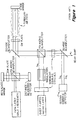
- Figure 1 illustrates a prior art device disclosed by Lis in U.S.P.N. 5,404,222, "Interferometric Measuring System with Air Turbulence Compensation", issued April 4, 1995, to make a direct measurement of the path length difference using second harmonic interferometry.
- Frequency doubling is applied at both the input and the output of the interferometer.
- Input frequency doubling provides two well-separated, phase-locked wavelengths (532 nm and 266 nm) to characterize the air in the path.
- the output frequency doubling allows accurate measurement of the small path length difference induced by the air by measuring an optical phase difference between the light which traveled as 532 nm and the light which traveled the path as 266 nm.
- the signal-to-noise ratio of the correction signal used for second harmonic interferometry is improved in two ways. First, an optical amplifier, tuned to the second harmonic frequency, is positioned in the optical path. Second, a doubling stage is positioned internal to the correction laser.
- An intracavity frequency doubled laser emits a first optical beam at a fundamental frequency and a second optical beam at the second-harmonic of the fundamental frequency.
- the frequency doubled laser is positioned adjacent to a phase modulator.
- a first beam splitter is positioned near the phase modulator.
- a second beam splitter is positioned between a reference laser, a quarter waveplate, and a face of the first beam splitter.
- a stage mirror is positioned proximate to the quarter waveplate. The system is designed to measure the stage mirror position.
- An external doubling crystal is positioned near an opposing face of the first beam splitter.
- An optical amplifier, tuned to the second harmonic frequency is positioned between the external doubling stage and a filter, such as a dichroic beamsplitter. The filter prevents the transmission of the first optical beam containing the fundamental frequency.
- a square law photo detector is positioned near the filter.
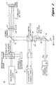
- FIG. 2 illustrates an interferometer of the present invention 10.
- An intracavity frequency doubled laser 12 emits a first optical beam at a fundamental frequency ⁇ c and a second optical beam at the second-harmonic of the fundamental frequency 2 ⁇ c .
- the frequency doubled laser 12 is positioned adjacent to a phase modulator 14.
- the phase modulator 14 applies a phase modulation to the first and second optical beams.
- a first beam splitter 16 is positioned near the phase modulator 14.
- a second beam combiner 18 is positioned between a reference laser 20, a quarter waveplate 22, and a face of the first beam splitter 16.
- a stage mirror 24 is positioned proximate to the quarter waveplate 22.
- An external doubling crystal stage 26 is positioned near an opposing face of the first beam splitter 16.
- An optical amplifier 28, tuned to the second harmonic frequency 2 ⁇ c is positioned between the external doubling crystal stage 26 and a filter 30, such as an output mirror.
- a second harmonic detector 32 is positioned near the filter 30.
- the optical amplifier 28 To avoid saturation, only the weak 2 ⁇ c beam generated at the end of the measurement path must pass through the optical amplifier 28. This requires at least a small amount of lateral separation. Displacement of the input beam by the width of the amplifier gain stripe (typically 50:m) will cause this. As long as the correction beams are separated by a few mm or less, the turbulence seen along their respective paths is well correlated and the separation should cause little error.
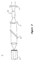
- Figure 3 illustrates an example of the intracavity frequency doubled laser 12 shown in Figure 2.
- a semiconductor laser 34 such as an InGaAsP laser diode, having an anti-reflective coating at the output, is positioned near an external field build-up cavity through an etalon 36.
- the build-up cavity includes a doubling crystal 38, such as KNBO 3 , positioned between two mirrors 40, 42.
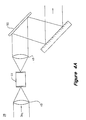
- Figures 4A and 4B illustrate examples of an optical amplifier 28 shown in Figure 2.
- the semiconductor optical amplifier 28 is made from an optical amplifier laser 44 having anti-reflective coatings at the input and the output is positioned between two collimators 46, 48.
- One of the two collimators 46, 48 is positioned near a diffraction grating 50.
- the diffraction grating 50 filters out the amplified spontaneous emission, i.e. minimizes all but the second harmonic frequency.
- an interference filter could be used to filter the amplified spontaneous emission.
- An alternate optical amplifier shown in Figure 4B, can be formed from a tilted stripe amplifier 52 having optional reflective coatings 54A, 54B.
- FIG. 5 illustrates a process flowchart according to the present invention.
- a first optical beam is generated at the fundamental frequency ⁇ c .
- a second optical beam is generated at the second harmonic of the fundamental frequency 2 ⁇ c .
- the first and second optical beams are emitted at one end of a measurement air path.
- a third optical beam is generated at the second harmonic frequency 2 ⁇ c at the other end of the measurement air path.
- the third optical beam is amplified.
- the second and third optical beams are interfered.
- the optical interference is converted into an electrical signal with a square lens photodetector.
- the electrical signal is used to correct for air turbulence in the interferometric distance measurements.
- the present invention has been described with respect to a separate measurement laser, if the intracavity doubled laser has sufficient frequency stability, the separate measurement laser can be eliminated and the dual wavelength output of a single laser can be used both for distance measurement and air turbulence correction.
Landscapes
- Physics & Mathematics (AREA)
- General Physics & Mathematics (AREA)
- Instruments For Measurement Of Length By Optical Means (AREA)
- Indication And Recording Devices For Special Purposes And Tariff Metering Devices (AREA)
Claims (10)
- Eine Korrekturvorrichtung mit folgenden Merkmalen:einer Verdopplungslasereinrichtung (12) zum Erzeugen eines ersten und eines zweiten optischen Strahls innerhalb eines Laserresonators der Verdopplungslasereinrichtung (12), wobei der erste optische Strahl bei einer Grundfrequenz ist und der zweite optische Strahl bei einer Frequenz einer zweiten Harmonischen ist;einem Phasenmodulator (14) zum Empfangen des ersten und des zweiten optischen Strahls, der wirksam ist, um eine Phasenmodulation des ersten und des zweiten optischen Strahls durchzuführen;einem Strahlteiler (16) zum Empfangen des modulierten ersten und zweiten optischen Strahls und zum Ausgeben des ersten und zweiten optischen Strahls an einen Messweg und Empfangen eines reflektierten ersten und eines reflektierten zweiten optischen Strahls von dem Messweg;einer Verdopplungskristallstufe (26), die in Verarbeitungsrichtung nach dem Strahlteiler positioniert ist, die wirksam ist, um die Frequenz des reflektierten ersten optischen Strahls zu verdoppeln;einem optischen Verstärker (28), der in Verarbeitungsrichtung nach der Verdopplungskristallstufe positioniert ist, der wirksam ist, um die Amplitude des frequenzverdoppelten, reflektierten ersten optischen Strahls zu verstärken;einem Filter (30), das in Verarbeitungsrichtung nach dem optischen Verstärker positioniert ist, und das wirksam ist, um den reflektierten ersten, den reflektierten zweiten und einen verstärkten frequenzverdoppelten, reflektierten ersten optischen Strahl zu empfangen und den reflektierten zweiten und den verstärkten, frequenzverdoppelten, reflektierten ersten optischen Strahl zu senden; undeinem Detektor (32) einer zweiten Harmonischen, der in Verarbeitungsrichtung nach dem Filter positioniert ist.
- Eine Korrekturvorrichtung gemäß Anspruch 1, wobei die Laserverdopplungseinrichtung folgende Merkmale aufweist:einen Halbleiterlaser (34), der einen antireflektionsbeschichteten Ausgang aufweist;ein Etalon (36), das benachbart zu dem antireflektionsbeschichteten Ausgang positioniert ist; undeinen Feldaufbauabschnitt, der folgende Merkmale umfasst:zwei Spiegel (40, 42), undeinen Verdopplungskristall (38), der zwischen den beiden Spiegeln positioniert ist.
- Eine Korrekturvorrichtung gemäß Anspruch 2, wobei der optische Verstärker folgende Merkmale aufweist:zwei Kollimatoren (46, 48);einen Halbleiterlaser (44), der zwischen den beiden Kollimatoren positioniert ist; undein optisches Filter (50), das benachbart zu einem der beiden Kollimatoren positioniert ist.
- Eine Korrekturvorrichtung gemäß Anspruch 3, bei der das optische Filter ein Beugungsgitter ist, das bei dem Signal einer Frequenz der zweiten Harmonischen optimiert ist.
- Eine Korrekturvorrichtung gemäß Anspruch 3, bei der das optische Filter ein Interferenzfilter ist, das bei dem Signal einer Frequenz der zweiten Harmonischen optimiert ist.
- Eine Korrekturvorrichtung gemäß Anspruch 3, bei der:der Halbleiterlaser der Laserverdopplungseinrichtung ein InGaAsP-Diodenlaser mit 1.300 nm ist; undder Halbleiterlaser des optischen Verstärkers eine InGaAlP-Diodenlaser bei 650 nm ist.
- Eine Korrekturvorrichtung gemäß Anspruch 1, wobei der optische Verstärker folgende Merkmale aufweist:zwei Kollimatoren (46, 48);einen Halbleiterlaser (44), der zwischen den beiden Kollimatoren positioniert ist; undein optisches Filter (50), das benachbart zu einem der zwei Kollimatoren positioniert ist.
- Eine Korrekturvorrichtung gemäß Anspruch 7, bei der das optische Filter ein Beugungsgitter (50) ist, das bei dem Signal einer Frequenz der zweiten Harmonischen optimiert ist.
- Eine Korrekturvorrichtung gemäß Anspruch 7, bei der das optische Filter ein Interferenzfilter ist, das bei dem Signal einer Frequenz der zweiten Harmonischen optimiert ist.
- Ein Verfahren zum Korrigieren von Luftturbulenzmessungen, mit folgenden Schritten:Erzeugen eines ersten optischen Strahls bei einer Grundfrequenz (100) und eines zweiten optischen Strahls bei der zweiten Harmonischen der Grundfrequenz (110) innerhalb eines Laserresonators einer Verdopplungslasereinrichtung (12);Senden des ersten und des zweiten optischen Strahls durch einen Messweg (120);Empfangen des reflektierten ersten und des reflektierten zweiten optischen Strahls von dem Messweg;Erzeugen eines dritten optischen Strahls bei der zweiten Harmonischen der Grundfrequenz durch Verdoppeln der Frequenz des reflektierten ersten optischen Strahls;Verstärken des dritten optischen Strahls (140);Interferieren des reflektierten zweiten und des verstärkten dritten optischen Strahls und Erzeugen eines optischen Signals (150);Umwandeln des optischen Signals in ein elektrisches Signal (160); undAnlegen des elektrischen Signals zur Korrektur einer Luftturbulenz entlang des Messwegs (170).
Applications Claiming Priority (2)
| Application Number | Priority Date | Filing Date | Title |
|---|---|---|---|
| US08/746,683 US5748313A (en) | 1996-11-14 | 1996-11-14 | Signal-to-noise ratio of second harmonic interferometers |
| US746683 | 1996-11-14 |
Publications (3)
| Publication Number | Publication Date |
|---|---|
| EP0843152A2 EP0843152A2 (de) | 1998-05-20 |
| EP0843152A3 EP0843152A3 (de) | 2000-02-23 |
| EP0843152B1 true EP0843152B1 (de) | 2006-01-25 |
Family
ID=25001886
Family Applications (1)
| Application Number | Title | Priority Date | Filing Date |
|---|---|---|---|
| EP97110052A Expired - Lifetime EP0843152B1 (de) | 1996-11-14 | 1997-06-19 | Verbesserung des Signal-Rauschverhältnisses eines 2. harmonischen Interferometers |
Country Status (5)
| Country | Link |
|---|---|
| US (1) | US5748313A (de) |
| EP (1) | EP0843152B1 (de) |
| JP (1) | JPH10153403A (de) |
| DE (1) | DE69735148T2 (de) |
| SG (1) | SG54508A1 (de) |
Cited By (2)
| Publication number | Priority date | Publication date | Assignee | Title |
|---|---|---|---|---|
| WO2008051232A2 (en) * | 2006-10-25 | 2008-05-02 | Zygo Corporation | Compensation of effects of atmospheric perturbations in optical metrology |
| CN101614523B (zh) * | 2009-08-10 | 2010-10-27 | 中国科学院长春光学精密机械与物理研究所 | 一种检测掠射筒状离轴非球面镜的多光束长轨干涉仪 |
Families Citing this family (16)
| Publication number | Priority date | Publication date | Assignee | Title |
|---|---|---|---|---|
| US6157458A (en) * | 1998-04-30 | 2000-12-05 | Agilent Technologies | Achromatic quarter wave plate for an air turbulence compensating inteferometer |
| US6014216A (en) * | 1999-01-08 | 2000-01-11 | Hewlett-Packard Company | Architecture for air-turbulence-compensated dual-wavelength heterodyne interferometer |
| US6256102B1 (en) | 1999-04-27 | 2001-07-03 | University Of Central Florida | Dual-beam low-coherence interferometer with improved signal-to-noise ratio |
| US6724486B1 (en) | 1999-04-28 | 2004-04-20 | Zygo Corporation | Helium- Neon laser light source generating two harmonically related, single- frequency wavelengths for use in displacement and dispersion measuring interferometry |
| US6417927B2 (en) * | 1999-04-28 | 2002-07-09 | Zygo Corporation | Method and apparatus for accurately compensating both long and short term fluctuations in the refractive index of air in an interferometer |
| EP1160627A3 (de) * | 2000-06-01 | 2004-08-18 | ASML Netherlands B.V. | Lithographischer Apparat, Verfahren zur Herstellung eines Artikels und damit hergestellter Artikel |
| US7508487B2 (en) | 2000-06-01 | 2009-03-24 | Asml Netherlands B.V. | Lithographic apparatus, device manufacturing method, and device manufactured thereby |
| US6816264B1 (en) | 2001-12-21 | 2004-11-09 | Itt Manufacturing Enterprises, Inc. | Systems and methods for amplified optical metrology |
| TWI304157B (en) * | 2002-11-27 | 2008-12-11 | Asml Netherlands Bv | Lithographic apparatus and device manufacturing method |
| US7826063B2 (en) | 2005-04-29 | 2010-11-02 | Zygo Corporation | Compensation of effects of atmospheric perturbations in optical metrology |
| US20070077071A1 (en) * | 2005-09-30 | 2007-04-05 | Mikhail Belenkiy | System for measuring atmospheric turbulence |
| JP5276595B2 (ja) | 2006-11-15 | 2013-08-28 | ザイゴ コーポレーション | リソグラフィツールにおいて使用される距離測定干渉計及びエンコーダ測定システム |
| US7894075B2 (en) | 2006-12-11 | 2011-02-22 | Zygo Corporation | Multiple-degree of freedom interferometer with compensation for gas effects |
| WO2008073486A2 (en) | 2006-12-11 | 2008-06-19 | Zygo Corporation | Multiple-degree of freedom interferometer with compensation for gas effects |
| GB201411206D0 (en) | 2014-06-24 | 2014-08-06 | Sec Dep For Business Innovation & Skills The And Usw Commercial Services Ltd | Dual laser frequency sweep interferometry system and method |
| DE102022120607A1 (de) | 2022-08-16 | 2024-02-22 | Deutsches Zentrum für Luft- und Raumfahrt e.V. | Optische Vorrichtung, System und Verfahren zur Dispersionsinterferometrie |
Family Cites Families (1)
| Publication number | Priority date | Publication date | Assignee | Title |
|---|---|---|---|---|
| US5404222A (en) * | 1994-01-14 | 1995-04-04 | Sparta, Inc. | Interferametric measuring system with air turbulence compensation |
-
1996
- 1996-11-14 US US08/746,683 patent/US5748313A/en not_active Expired - Fee Related
-
1997
- 1997-06-04 SG SG1997001918A patent/SG54508A1/en unknown
- 1997-06-19 DE DE69735148T patent/DE69735148T2/de not_active Expired - Fee Related
- 1997-06-19 EP EP97110052A patent/EP0843152B1/de not_active Expired - Lifetime
- 1997-11-12 JP JP9310319A patent/JPH10153403A/ja active Pending
Cited By (3)
| Publication number | Priority date | Publication date | Assignee | Title |
|---|---|---|---|---|
| WO2008051232A2 (en) * | 2006-10-25 | 2008-05-02 | Zygo Corporation | Compensation of effects of atmospheric perturbations in optical metrology |
| WO2008051232A3 (en) * | 2006-10-25 | 2009-05-07 | Zygo Corp | Compensation of effects of atmospheric perturbations in optical metrology |
| CN101614523B (zh) * | 2009-08-10 | 2010-10-27 | 中国科学院长春光学精密机械与物理研究所 | 一种检测掠射筒状离轴非球面镜的多光束长轨干涉仪 |
Also Published As
| Publication number | Publication date |
|---|---|
| DE69735148T2 (de) | 2006-07-20 |
| EP0843152A2 (de) | 1998-05-20 |
| DE69735148D1 (de) | 2006-04-13 |
| SG54508A1 (en) | 1998-11-16 |
| EP0843152A3 (de) | 2000-02-23 |
| US5748313A (en) | 1998-05-05 |
| JPH10153403A (ja) | 1998-06-09 |
Similar Documents
| Publication | Publication Date | Title |
|---|---|---|
| EP0843152B1 (de) | Verbesserung des Signal-Rauschverhältnisses eines 2. harmonischen Interferometers | |
| US4856899A (en) | Optical frequency analyzer using a local oscillator heterodyne detection of incident light | |
| US6366592B1 (en) | Stepped etalon semiconductor laser wavelength locker | |
| US5404222A (en) | Interferametric measuring system with air turbulence compensation | |
| JP2810956B2 (ja) | 絶対干渉測定方法 | |
| US6339603B1 (en) | Tunable laser with polarization anisotropic amplifier for fabry-perot filter reflection isolation | |
| EP0498575A2 (de) | Interferometer mit 2-Farben geregelten Laserdioden | |
| JP2010112768A (ja) | 計測装置 | |
| US6573996B1 (en) | Method and apparatus for enhanced precision interferometric distance measurement | |
| JP2010261890A (ja) | 光波干渉計測装置 | |
| US6738187B2 (en) | Semiconductor optical amplifiers using wavelength locked loop tuning and equalization | |
| JP3950570B2 (ja) | 周波数安定化光源 | |
| JPH11211571A (ja) | 波長測定装置 | |
| JP2744728B2 (ja) | ガス濃度測定方法およびその測定装置 | |
| CN110829167A (zh) | 一种抑制激光器单频相位噪声的方法及系统 | |
| JPH09166414A (ja) | 光計測装置 | |
| US7333210B2 (en) | Method and apparatus for feedback control of tunable laser wavelength | |
| JP3342055B2 (ja) | ヘテロダイン干渉測長器 | |
| US6243401B1 (en) | Methods and apparatus for wavelength measurement and tracking using a semiconductor laser amplifier | |
| JP2962568B2 (ja) | 周波数安定化レーザ光源 | |
| JPH1096601A (ja) | 光波干渉測定装置 | |
| JPH10132737A (ja) | 遠隔ガス濃度測定方法及びその装置 | |
| JP2007515769A (ja) | レーザ角度制御 | |
| JP3095036B2 (ja) | 回折格子を用いた位置ずれ量測定方法及びその装置 | |
| JPH067099B2 (ja) | チューナブルエタロンを用いたガスセンサ |
Legal Events
| Date | Code | Title | Description |
|---|---|---|---|
| PUAI | Public reference made under article 153(3) epc to a published international application that has entered the european phase |
Free format text: ORIGINAL CODE: 0009012 |
|
| AK | Designated contracting states |
Kind code of ref document: A2 Designated state(s): DE FR GB NL |
|
| AX | Request for extension of the european patent |
Free format text: AL;LT;LV;RO;SI |
|
| PUAL | Search report despatched |
Free format text: ORIGINAL CODE: 0009013 |
|
| AK | Designated contracting states |
Kind code of ref document: A3 Designated state(s): AT BE CH DE DK ES FI FR GB GR IE IT LI LU MC NL PT SE |
|
| AX | Request for extension of the european patent |
Free format text: AL;LT;LV;RO;SI |
|
| 17P | Request for examination filed |
Effective date: 20000329 |
|
| AKX | Designation fees paid |
Free format text: DE FR GB NL |
|
| RAP1 | Party data changed (applicant data changed or rights of an application transferred) |
Owner name: HEWLETT-PACKARD COMPANY, A DELAWARE CORPORATION |
|
| RAP1 | Party data changed (applicant data changed or rights of an application transferred) |
Owner name: AGILENT TECHNOLOGIES, INC. |
|
| RAP1 | Party data changed (applicant data changed or rights of an application transferred) |
Owner name: AGILENT TECHNOLOGIES INC. |
|
| RAP1 | Party data changed (applicant data changed or rights of an application transferred) |
Owner name: AGILENT TECHNOLOGIES INC. A DELAWARE CORPORATION |
|
| RAP1 | Party data changed (applicant data changed or rights of an application transferred) |
Owner name: AGILENT TECHNOLOGIES, INC. (A DELAWARE CORPORATION |
|
| 17Q | First examination report despatched |
Effective date: 20011129 |
|
| GRAP | Despatch of communication of intention to grant a patent |
Free format text: ORIGINAL CODE: EPIDOSNIGR1 |
|
| GRAS | Grant fee paid |
Free format text: ORIGINAL CODE: EPIDOSNIGR3 |
|
| GRAA | (expected) grant |
Free format text: ORIGINAL CODE: 0009210 |
|
| AK | Designated contracting states |
Kind code of ref document: B1 Designated state(s): DE FR GB NL |
|
| REG | Reference to a national code |
Ref country code: GB Ref legal event code: FG4D |
|
| REF | Corresponds to: |
Ref document number: 69735148 Country of ref document: DE Date of ref document: 20060413 Kind code of ref document: P |
|
| PGFP | Annual fee paid to national office [announced via postgrant information from national office to epo] |
Ref country code: FR Payment date: 20060620 Year of fee payment: 10 |
|
| PGFP | Annual fee paid to national office [announced via postgrant information from national office to epo] |
Ref country code: NL Payment date: 20060624 Year of fee payment: 10 |
|
| PGFP | Annual fee paid to national office [announced via postgrant information from national office to epo] |
Ref country code: GB Payment date: 20060626 Year of fee payment: 10 |
|
| PGFP | Annual fee paid to national office [announced via postgrant information from national office to epo] |
Ref country code: DE Payment date: 20060731 Year of fee payment: 10 |
|
| PLBE | No opposition filed within time limit |
Free format text: ORIGINAL CODE: 0009261 |
|
| STAA | Information on the status of an ep patent application or granted ep patent |
Free format text: STATUS: NO OPPOSITION FILED WITHIN TIME LIMIT |
|
| 26N | No opposition filed |
Effective date: 20061026 |
|
| GBPC | Gb: european patent ceased through non-payment of renewal fee |
Effective date: 20070619 |
|
| NLV4 | Nl: lapsed or anulled due to non-payment of the annual fee |
Effective date: 20080101 |
|
| PG25 | Lapsed in a contracting state [announced via postgrant information from national office to epo] |
Ref country code: NL Free format text: LAPSE BECAUSE OF NON-PAYMENT OF DUE FEES Effective date: 20080101 Ref country code: FR Free format text: LAPSE BECAUSE OF FAILURE TO SUBMIT A TRANSLATION OF THE DESCRIPTION OR TO PAY THE FEE WITHIN THE PRESCRIBED TIME-LIMIT Effective date: 20070316 Ref country code: DE Free format text: LAPSE BECAUSE OF NON-PAYMENT OF DUE FEES Effective date: 20080101 |
|
| PG25 | Lapsed in a contracting state [announced via postgrant information from national office to epo] |
Ref country code: GB Free format text: LAPSE BECAUSE OF NON-PAYMENT OF DUE FEES Effective date: 20070619 |