EP0843104A2 - Vorrichtung zum Verbinden dreier Längselemente - Google Patents
Vorrichtung zum Verbinden dreier Längselemente Download PDFInfo
- Publication number
- EP0843104A2 EP0843104A2 EP97118805A EP97118805A EP0843104A2 EP 0843104 A2 EP0843104 A2 EP 0843104A2 EP 97118805 A EP97118805 A EP 97118805A EP 97118805 A EP97118805 A EP 97118805A EP 0843104 A2 EP0843104 A2 EP 0843104A2
- Authority
- EP
- European Patent Office
- Prior art keywords
- longitudinal
- holding
- angle
- elements
- holding leg
- Prior art date
- Legal status (The legal status is an assumption and is not a legal conclusion. Google has not performed a legal analysis and makes no representation as to the accuracy of the status listed.)
- Withdrawn
Links
Images

Classifications
-
- F—MECHANICAL ENGINEERING; LIGHTING; HEATING; WEAPONS; BLASTING
- F16—ENGINEERING ELEMENTS AND UNITS; GENERAL MEASURES FOR PRODUCING AND MAINTAINING EFFECTIVE FUNCTIONING OF MACHINES OR INSTALLATIONS; THERMAL INSULATION IN GENERAL
- F16B—DEVICES FOR FASTENING OR SECURING CONSTRUCTIONAL ELEMENTS OR MACHINE PARTS TOGETHER, e.g. NAILS, BOLTS, CIRCLIPS, CLAMPS, CLIPS OR WEDGES; JOINTS OR JOINTING
- F16B7/00—Connections of rods or tubes, e.g. of non-circular section, mutually, including resilient connections
- F16B7/18—Connections of rods or tubes, e.g. of non-circular section, mutually, including resilient connections using screw-thread elements
- F16B7/187—Connections of rods or tubes, e.g. of non-circular section, mutually, including resilient connections using screw-thread elements with sliding nuts or other additional connecting members for joining profiles provided with grooves or channels
-
- E—FIXED CONSTRUCTIONS
- E04—BUILDING
- E04B—GENERAL BUILDING CONSTRUCTIONS; WALLS, e.g. PARTITIONS; ROOFS; FLOORS; CEILINGS; INSULATION OR OTHER PROTECTION OF BUILDINGS
- E04B1/00—Constructions in general; Structures which are not restricted either to walls, e.g. partitions, or floors or ceilings or roofs
- E04B1/38—Connections for building structures in general
- E04B1/58—Connections for building structures in general of bar-shaped building elements
-
- F—MECHANICAL ENGINEERING; LIGHTING; HEATING; WEAPONS; BLASTING
- F16—ENGINEERING ELEMENTS AND UNITS; GENERAL MEASURES FOR PRODUCING AND MAINTAINING EFFECTIVE FUNCTIONING OF MACHINES OR INSTALLATIONS; THERMAL INSULATION IN GENERAL
- F16B—DEVICES FOR FASTENING OR SECURING CONSTRUCTIONAL ELEMENTS OR MACHINE PARTS TOGETHER, e.g. NAILS, BOLTS, CIRCLIPS, CLAMPS, CLIPS OR WEDGES; JOINTS OR JOINTING
- F16B12/00—Jointing of furniture or the like, e.g. hidden from exterior
- F16B12/44—Leg joints; Corner joints
- F16B12/50—Metal corner connections
-
- E—FIXED CONSTRUCTIONS
- E04—BUILDING
- E04B—GENERAL BUILDING CONSTRUCTIONS; WALLS, e.g. PARTITIONS; ROOFS; FLOORS; CEILINGS; INSULATION OR OTHER PROTECTION OF BUILDINGS
- E04B1/00—Constructions in general; Structures which are not restricted either to walls, e.g. partitions, or floors or ceilings or roofs
- E04B1/38—Connections for building structures in general
- E04B1/388—Separate connecting elements
- E04B2001/389—Brackets
-
- H—ELECTRICITY
- H02—GENERATION; CONVERSION OR DISTRIBUTION OF ELECTRIC POWER
- H02B—BOARDS, SUBSTATIONS OR SWITCHING ARRANGEMENTS FOR THE SUPPLY OR DISTRIBUTION OF ELECTRIC POWER
- H02B1/00—Frameworks, boards, panels, desks, casings; Details of substations or switching arrangements
- H02B1/01—Frameworks
- H02B1/014—Corner connections for frameworks
Definitions
- the invention relates to a device for connecting three Longitudinal elements at a node, with each longitudinal element runs at right angles to the other two longitudinal elements, with a three-armed connecting body, the three arms also aligned at right angles to each other and on their the inner arm ends facing the node in one piece are connected, each arm on a longitudinal element can be created and with this by means of at least one Clamping device is releasably connectable, one in a Provided longitudinal element, extending in the longitudinal direction Anchoring groove positionable sliding block and a with working together with the sliding block, supporting itself on the arm Fastener contains.
- Such a device is apparent from DE-PS 817 191. It is used, for example, when building frames, frames, Scaffolding and the like used.
- a disadvantage of this construction is that the device does not have sufficient strength, especially compared to those occurring on the longitudinal elements Bending moments around the node.
- connection of longitudinal elements that have a rectangular cross-section and one on at least two adjacent long sides Have anchoring groove, a respective arm as an angle element is formed, the two seen at right angles in cross section has interconnected holding legs, wherein the holding legs of a respective angle element with one holding leg each from one of the other two angle elements are connected that between the holding legs of a respective angular element connecting edges meet at a common point so that a respective angular element with the inner surfaces of its two Holding leg flat on two adjacent long sides of the associated longitudinal element can be created and the one anchoring groove assigned to each longitudinal side in this way reaches over that the angle element with each holding leg under Mediation of a clamping device assigned to this can be clamped with the associated longitudinal element, and that the two in the area of the inner arm ends with each other connected holding leg of two angle elements in the area their respective outer edges facing away from the connecting edge connected to each other by means of a stiffening body are.
- the stiffening bodies are expediently of triangular, having a right angle, in particular isosceles triangular plates formed, the right Angle facing the assigned inner arm ends is. Such a stiffening body takes up little space, avoids protruding corners and edges and ensures a very high stability.
- stiffening body over the entire length of the associated holding legs these are connected. In this way, the stiffening body with a bending moment occurring around the node absorb the greatest possible force and accordingly ensure good strength of the connecting body.
- a respective holding leg preferably has for passage a fastener over at least one, with the anchoring groove overlapped by this holding leg of the associated longitudinal element aligned opening.
- the fastener of one Screw be formed. This results in a very simple one Possibility in connection with an assigned sliding block to realize a tensioning device. At the same time also a secure connection between the connector body and assigned longitudinal element reached.
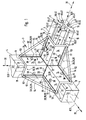
- Figure 1 is a device 3 for connecting three Longitudinal elements 4 shown. With the help of such devices 3 can be made from longitudinal elements 4 any constructions such as building frames, frames or scaffolding.
- the longitudinal elements 4 are expediently as extruded profile parts executed and preferably consist of Aluminum material.
- the device according to the example enables the releasable fixed Connection of longitudinal elements 4 in such a way that each Longitudinal element, as shown, at right angles to the other two Longitudinal elements 4 is aligned. All three longitudinal elements thus form a node 5 in which the respective Cut the longitudinal axes 8 of the longitudinal elements 4.
- the node 5 can be designed as a corner, if all three Longitudinal elements 4 from the node 5 along their respective Extend longitudinal axis 8 only in one direction. In contrast it is of course also possible that a longitudinal element 4 along its longitudinal axis 8 through the node 5 extends in both directions.
- the device 3 contains a three-armed Connecting body 9, the three arms 10 on one of each to be connected longitudinal elements 4 and so their position set relative to each other.
- the arms 10 of the connecting body 9 also at right angles to one another aligned.
- the longitudinal axes 13 of the arms 10 are there perpendicular to a Cartesian coordinate system on each other.
- a respective arm 10 is an angular element 15 formed and has two rectangular in cross section interconnected holding leg 14 on a Connecting edge 16 running parallel to the longitudinal axis 13 are fixed together in one piece.
- the exemplary connecting device enables in particular connecting longitudinal elements 4, which are rectangular Have cross-section and four at right angles to each other have aligned long sides 11.
- the longitudinal elements 4 are thus assigned to one of each Angle element 15 formed arm 10 of a connecting body 9 can be applied that a respective angle element 15 with its two the associated longitudinal element 4 facing inner surfaces 18 on two directly adjacent long sides of this Longitudinal element 4 lies flat.
- the on the legs 14 provided inner surfaces 18 of each Angle element 15 form a right angle and limit thus a partial space, which is designated as the receiving area 19 be.
- the arms 10 of the connecting body designed as angle elements 15 9 are now at their node 5 facing, axially inner arm ends 20 in one piece connected that a respective inner surface 18 of a Holding leg 14 of an angular element 15 in the area of her assigned inner arm end 20 an inner surface 18 of a Holding leg 14 of another angle element 15 connects.
- Those in the area of a respective inner arm end 20 adjacent inner surfaces 18 of different angular elements 15 here close an angle of approximately 270 ° a.
- the angle elements 15 are thus in the region of their facing each other inner arm ends 20 connected such that in the area of a respective inner arm end 20 on the Longitudinal elements 4 facing side of the connecting body 9 each inner surfaces 18 of each holding leg 14 to each other adjoin, and that on the opposite, the longitudinal elements 4 opposite side of the connecting body 9 each Connect outer surfaces 23 of the holding legs 14 to one another.
- the connecting body 9 defines an in Direction of the inner surfaces 18 facing inner region 24 and a complementary trained, in the direction of the respective Outer surfaces 23 facing outer area 25.
- the longitudinal elements 4 are located in the inner region 24.
- this Structure of the connecting body 9 is the same to the longitudinal elements 4 starting from a node 5 possible from one side.
- clamping devices 28 are provided for releasable attachment of the connecting body 9 to the Longitudinal elements 4 clamping devices 28 are provided.
- each holding leg 14 an arm 10 formed by an angular element 15 has its own Assigned clamping device 28.
- the example Tensioning devices 28 each have an associated one Holding leg 14 supporting fastener 29 and a in a provided on a respective longitudinal element 4, in the longitudinal direction 30 extending anchoring groove 33 held Sliding block 34 on.
- the fastener 29 is for example formed by a screw 35.
- Each longitudinal element 4 has at least two neighboring ones Longitudinal sides 11 an anchoring groove 33.
- a respective anchoring groove 33 is undercut. Seen in cross-section is the one on each Longitudinal side 11 in the longitudinal direction 8 slit-like Groove opening 41 along a respective anchoring groove 33 of its two long sides 42 by one parallel to each Outer surface 45 of the longitudinal element 4 extending projection 46 narrowed. Viewed inwards from the slot opening 41 joins this to the movable recording and Positioning of the sliding block 34 provided extended Anchoring portion 47 to that of the groove opening 41 opposite, inner groove base 50 of the anchoring groove 33 can in turn narrow.
- a respective holding leg 14 has an opening 38 which, when the longitudinal element 4 is attached in the receiving area 19 with an anchoring groove 33 on the facing long side 11 of the associated longitudinal element 4 is aligned.
- Anchoring groove 33 is from the associated holding leg 14 attacks.
- Each opening 38 is one of the mentioned screws 35 assigned, so from the outside the associated opening 38 can be passed through that their screw head on the outer surface 23 of the associated Support leg 14 supports. Between each one Screw head and the outer surface 23 of an associated Holding leg 14 can also be a washer as shown 40 be interposed.
- the fastener configured as a screw 35 for example 29 reaches through in the connected state Opening 38 and the aligned groove opening 41 in the assigned sliding block 34, so that the assigned Longitudinal element 4 by means of the nut 34 loaded by the sliding block Protrusions 46 on the inner surface 18 of the associated holding leg 14 is pressed.
- To pressurize the sliding block To enable 34 by the screw 35 is in these introduced an internal thread, not shown. In this way, a respective longitudinal element 4 on two adjacent long sides 11 with the associated arm 10 of the Connection body 4 clamped.
- Two holding legs 14 each with different angle elements 15, which in the region of a respective inner arm end 20 have an integral connection are along their in Longitudinal direction 30, facing away from the connecting edge 16 Outer edges 51 by means of a rigid stiffening body 52 interconnected.
- the example Stiffening body 52 has a plate-like shape and one right corner 55. This is right-angled Corner 55 of the two inner arm ends 20 of the associated Holding elements 14 facing and is in the region of the connecting lines 22 on the inner arm ends 20.
- the stiffening body 52 has one triangular shape.
- the edge length of the cathete this right triangle corresponds to the respective length of the associated holding leg 14, wherein a respective stiffening body 52 with its catheter edges 53 on a respective one Holding leg 14 seen in the longitudinal direction 30 over the entire Length whose outer edge 51 is fixed.
- the exemplary embodiment is the length of the holding legs 14 in a respective longitudinal direction 30 of the same size, so that the stiffening body 52 in the side view the shape of a right-angled, isosceles triangle.
- the end edge 54 forming the hypotenuse of the triangle the stiffening body 52 extends obliquely between the outer arm ends 21 of the respectively connected holding legs 14. This avoids protruding corners and you get one compact design.
- the stiffening bodies are 52 by extending along the catheter edges 53 Welded connections on the respectively associated holding leg 14 fixed. Also the one-piece connection between the angle elements 15 in the connection area of their inner arms 20 is expediently realized by welded connections.
- the entire connecting body 9 expediently consists of Metal like steel or aluminum material, it could in principle but also be made of plastic material. He could instead of a one-piece assembly of several elements also be made as a one-piece element, for example as a casting.
Landscapes
- Engineering & Computer Science (AREA)
- General Engineering & Computer Science (AREA)
- Architecture (AREA)
- Mechanical Engineering (AREA)
- Civil Engineering (AREA)
- Electromagnetism (AREA)
- Physics & Mathematics (AREA)
- Structural Engineering (AREA)
- Vehicle Body Suspensions (AREA)
- Handcart (AREA)
- Superconductors And Manufacturing Methods Therefor (AREA)
- Coupling Device And Connection With Printed Circuit (AREA)
- Mutual Connection Of Rods And Tubes (AREA)
Abstract
Description
- Figur 1
- eine bevorzugte Ausführungsform der erfindungsgemäßen Vorrichtung mit einem Verbindungskörper und den zugeordneten Längselementen im Schrägbild,
- Figur 2
- die Vorrichtung aus Figur 1 in einer Seitenansicht gemäß Pfeil II.
Claims (9)
- Vorrichtung zum Verbinden dreier Längselemente (4) an einer Knotenstelle (5), wobei jedes Längselement (4) rechtwinkelig zu den beiden anderen Längselementen (4) verläuft, mit einem dreiarmigen Verbindungskörper (9), dessen drei Arme (10) ebenfalls rechtwinkelig zueinander ausgerichtet und an ihren der Knotenstelle (5) zugewandten inneren Armenden (20) einstückig miteinander verbunden sind, wobei jeder Arm (10) an einem Längselement (4) anlegbar und mit diesem mittels wenigstens einer Spanneinrichtung (28) lösbar verbindbar ist, die einen in einer am Längselement (4) vorgesehenen, in dessen Längsrichtung (30) verlaufenden Verankerungsnut (33) positionierbaren Nutenstein (34) und ein mit dem Nutenstein (34) zusammenarbeitendes, sich am Arm (10) abstützendes Befestigungselement (29) enthält, dadurch gekennzeichnet, daß zur Verbindung von Längselementen (4), die einen rechteckigen Querschnitt und an mindestens zwei benachbarten Längsseiten eine Verankerungsnut (33) aufweisen, ein jeweiliger Arm (10) als Winkelelement (15) ausgebildet ist, das zwei im Querschnitt gesehen rechtwinkelig miteinander verbundene Halteschenkel (14) aufweist, wobei die Halteschenkel (14) eines jeweiligen Winkelelementes (15) derart mit jeweils einem Haltschenkel (14) von einem der beiden anderen Winkelelemente (15) verbunden sind, daß sich die zwischen den Halteschenkeln (14) eines jeweiligen Winkelelementes (15) verlaufenden Verbindungskanten (16) in einem gemeinsamen Punkt treffen, so daß ein jeweiliges Winkelelement (15) mit den Innenflächen (18) seiner beiden Halteschenkel (14) flächig an zwei benachbarten Längsseiten des zugeordneten Längselementes (4) anlegbar ist und dabei die einer jeweiligen Längsseite Zugeordnete Verankerungsnut (33) derart übergreift, daß das Winkelelement (15) mit jedem Halteschenkel (14) unter Vermittlung einer diesem zugeordneten Spanneinrichtung (28) mit dem zugeordneten Längselement (4) verspannbar ist, und daß die zwei im Bereich der inneren Armenden (20) jeweils miteinander verbundenen Halteschenkel (14) zweier Winkelelemente (15) im Bereich ihrer jeweiligen, der Verbindungskante (16) abgewandten Außenkanten (51) mittels eines Versteifungskörpers (52) untereinander verbunden sind.
- Vorrichtung nach Anspruch 1, dadurch gekennzeichnet, daß die Versteifungskörper (52) von dreieckförmigen, einen rechten Winkel aufweisenden, insbesondere gleichschenkeligen Dreiecksplatten gebildet sind, deren rechter Winkel den jeweils zugeordneten inneren Armenden (20) zugewandt ist.
- Vorrichtung nach Anspruch 1 oder 2, dadurch gekennzeichnet, daß die Versteifungskörper (52) über die gesamte Länge der zugeordneten Halteschenkel (14) mit diesen verbunden sind.
- Vorrichtung nach einem der Ansprüche 1 bis 3, dadurch gekennzeichnet, daß die Versteifungskörper (52) zur einstückigen Verbindung mit den Armen (10) durch Schweißverbindungen an den betreffenden Halteschenkeln (14) festgelegt sind.
- Vorrichtung nach einem der Ansprüche 1 bis 4, dadurch gekennzeichnet, daß die Arme (10) des Verbindungskörpers (9) zu Ihrer einstückigen Verbindung durch Schweißverbindungen aneinander festgelegt sind.
- Vorrichtung nach einem der Ansprüche 1 bis 5, dadurch gekennzeichnet, daß die Längselemente (4) einen quadratischen Querschnitt aufweisen.
- Vorrichtung nach einem der Ansprüche 1 bis 6, dadurch gekennzeichnet, daß die Längselemente (4) auf jeder Längsseite wenigstens eine längsverlaufende Verankerungsnut (33) aufweisen.
- Vorrichtung nach einem der Ansprüche 1 bis 7, dadurch gekennzeichnet, daß ein jeweiliger Halteschenkel (14) zur Durchführung eines Befestigungselementes (29) wenigstens eine bei angesetztem Längselement (4) mit der von diesem Halteschenkel (14) übergriffenen Verankerungsnut (33) des Längselementes (4) fluchtende Durchbrechung (38) aufweist.
- Vorrichtung nach einem der Ansprüche 1 bis 8, dadurch gekennzeichnet, daß das Befestigungselement (29) von einer Schraube (35) gebildet ist.
Applications Claiming Priority (2)
| Application Number | Priority Date | Filing Date | Title |
|---|---|---|---|
| DE29619965U | 1996-11-16 | ||
| DE29619965U DE29619965U1 (de) | 1996-11-16 | 1996-11-16 | Vorrichtung zum Verbinden dreier Längselemente |
Publications (2)
| Publication Number | Publication Date |
|---|---|
| EP0843104A2 true EP0843104A2 (de) | 1998-05-20 |
| EP0843104A3 EP0843104A3 (de) | 1999-11-17 |
Family
ID=8032048
Family Applications (1)
| Application Number | Title | Priority Date | Filing Date |
|---|---|---|---|
| EP97118805A Withdrawn EP0843104A3 (de) | 1996-11-16 | 1997-10-29 | Vorrichtung zum Verbinden dreier Längselemente |
Country Status (2)
| Country | Link |
|---|---|
| EP (1) | EP0843104A3 (de) |
| DE (1) | DE29619965U1 (de) |
Cited By (3)
| Publication number | Priority date | Publication date | Assignee | Title |
|---|---|---|---|---|
| WO2000043604A1 (en) * | 1999-01-19 | 2000-07-27 | Paul James Sibert | Assembly system and components therefor |
| DE10155632C1 (de) * | 2001-11-13 | 2003-02-20 | Roger Elektronikbauteile Gmbh | Rahmengestell für einen Schaltschrank |
| EP3252892B1 (de) * | 2016-05-31 | 2021-07-28 | Bombardier Transportation GmbH | Schienenfahrzeug mit einem schrank |
Families Citing this family (5)
| Publication number | Priority date | Publication date | Assignee | Title |
|---|---|---|---|---|
| DE29806711U1 (de) * | 1998-04-14 | 1999-08-12 | fischerwerke Artur Fischer GmbH & Co. KG, 72178 Waldachtal | Winkelverbindungselement |
| DE202004001941U1 (de) * | 2004-02-10 | 2004-09-09 | Willkomm, Dirk | Knotenwinkel 90 Grad zum Herstellen eines rechtwinkligen Verbindungsknoten bei Aluminium-Profilsystemen |
| CN101463628B (zh) * | 2008-04-29 | 2011-05-04 | 甘秀明 | 半蝶型连接卡及建筑钢框架节点结构 |
| CN102021947B (zh) * | 2010-11-18 | 2011-11-30 | 甘秀明 | 建筑钢框架节点结构 |
| CN104393491A (zh) * | 2014-12-15 | 2015-03-04 | 广西春茂电气自动化工程有限公司 | 一种拼接式框架的双重加强角连接结构 |
Family Cites Families (19)
| Publication number | Priority date | Publication date | Assignee | Title |
|---|---|---|---|---|
| DE7340663U (de) * | 1974-03-07 | Bbc Ag | Eckverbindung zur räumlichen Verbindung dreier gelochter Profilschienen | |
| US2345650A (en) * | 1940-10-12 | 1944-04-04 | Charles W Attwood | Skeletonized structure |
| US2380379A (en) * | 1942-11-04 | 1945-07-31 | Charles W Attwood | Table |
| DE817191C (de) * | 1949-10-18 | 1951-10-15 | Kurt Huebner | Rahmenleiste |
| BE569069A (de) * | 1958-06-26 | |||
| GB935434A (en) * | 1960-03-01 | 1963-08-28 | Alfred Imhof Ltd | Improvements in or relating to rigid frameworks for use in constructing racks, cabinets, boxes or the like |
| US3353854A (en) * | 1965-04-09 | 1967-11-21 | Gen Electric | Structural corner assembly |
| US3601430A (en) * | 1967-12-13 | 1971-08-24 | Hendrik Pieter Zwennis | Joints between structural members |
| DE2222574A1 (de) * | 1972-02-01 | 1973-08-09 | Ifa Karosseriewerke Veb | Formschluessige verbindungselemente fuer gerippekonstruktionen, insbesondere fuer fahrzeugaufbauten und transportbehaelter |
| FR2141012A5 (de) * | 1972-02-07 | 1973-01-19 | Gournelle Maurice | |
| US4136985A (en) * | 1977-07-07 | 1979-01-30 | Massey-Ferguson Inc. | Corner structure |
| DE3200310C2 (de) * | 1982-01-08 | 1984-12-13 | Ernst Binningen Koller | Gestell aus mehreren Profilstäben |
| FR2603351B1 (fr) * | 1986-08-28 | 1988-11-18 | Cure Alain | Noeud d'assemblage modulaire pour elements profiles |
| DE8912365U1 (de) * | 1989-10-18 | 1990-11-15 | Dinstühler, Manfred, 5609 Hückeswagen | Rohrmuffenverbinder |
| DE4306877C3 (de) * | 1993-03-05 | 1999-04-29 | Ziegler Albert Gmbh Co Kg | Profilstabsystem für Rahmenkonstruktionen, Fahrzeugaufbauten, Regalsysteme, Werkstatt- und Laboreinrichtungen od. dgl. |
| DE9306714U1 (de) * | 1993-05-04 | 1994-09-15 | Halfen GmbH & Co. KG, 40591 Düsseldorf | Vorrichtung zum knotenblechähnlichen Verbinden/Stabilisieren von über Eck zueinander verlaufenden Bauteilen |
| CA2136574C (en) * | 1993-12-03 | 1999-11-16 | John Kemp | Trader desk frame |
| DE9415356U1 (de) * | 1994-01-05 | 1994-11-24 | Schnaithmann Maschinenbau GmbH, 73630 Remshalden | Profilverbindung von Tragprofilen |
| DE19507764A1 (de) * | 1995-03-06 | 1996-09-12 | Rost & Co Gmbh | Verbindungseinheit |
-
1996
- 1996-11-16 DE DE29619965U patent/DE29619965U1/de not_active Expired - Lifetime
-
1997
- 1997-10-29 EP EP97118805A patent/EP0843104A3/de not_active Withdrawn
Cited By (3)
| Publication number | Priority date | Publication date | Assignee | Title |
|---|---|---|---|---|
| WO2000043604A1 (en) * | 1999-01-19 | 2000-07-27 | Paul James Sibert | Assembly system and components therefor |
| DE10155632C1 (de) * | 2001-11-13 | 2003-02-20 | Roger Elektronikbauteile Gmbh | Rahmengestell für einen Schaltschrank |
| EP3252892B1 (de) * | 2016-05-31 | 2021-07-28 | Bombardier Transportation GmbH | Schienenfahrzeug mit einem schrank |
Also Published As
| Publication number | Publication date |
|---|---|
| DE29619965U1 (de) | 1997-01-09 |
| EP0843104A3 (de) | 1999-11-17 |
Similar Documents
| Publication | Publication Date | Title |
|---|---|---|
| EP0615071B1 (de) | Halteelement aus Kunststoff | |
| DE4317599A1 (de) | Scharniersystem für Gehäuse elektrischer Anlagen | |
| DE2828424B2 (de) | Kamera-Stativ | |
| EP1317631A1 (de) | Verbindungsteil für montageschienen | |
| DE2324184C3 (de) | Einrichtung zum Verbinden von Elementen eines Tragwerks | |
| DE1957380B2 (de) | Aufsetzkranz fuer dachoberlichte | |
| WO2017016844A1 (de) | Befestigungsanordnung, clipkörper und clip | |
| EP0843104A2 (de) | Vorrichtung zum Verbinden dreier Längselemente | |
| DE20015831U1 (de) | Teleskopierbarer Linearantrieb | |
| DE8030908U1 (de) | Vorrichtung zum verbinden von platten und/oder staeben | |
| WO2015074933A1 (de) | Haltevorrichtung für ein gehäuse und verfahren zur montage des gehäuses unter verwendung der haltevorrichtung | |
| DE2943191A1 (de) | Befestigungsanordnung fuer eine an einer blechplatte anzubringende mutter | |
| DE4306802C1 (de) | Deckenstativ | |
| DE29706495U1 (de) | Verbindungskörper zur Verbindung von Längselementen | |
| DE2413707B2 (de) | Verbindungselement fuer hohlprofilteile, insbesondere eckverbinder | |
| DE102007055479B4 (de) | Knotenelement für eine Fachwerkskonstruktion | |
| DE8224861U1 (de) | Aus Profilteilen bestehendes Gestell | |
| DE3232766C1 (de) | Aus Profilteilen bestehendes Gestell | |
| DE3728324C2 (de) | ||
| DE102023102127A1 (de) | Eckverbinder mit Spreizelement | |
| DE2944557C2 (de) | Verbindung für Flächenkonstruktionselemente oder dgl. | |
| DE202025104335U1 (de) | Vorrichtung zur Montage eines Fensterrahmens an einem Rolladenkasten | |
| DE102014007069A1 (de) | System zum Zusammensetzen zweier Bausteile | |
| DE9314824U1 (de) | Schraubverbindung | |
| DE3734533A1 (de) | Knotenpunktsystem fuer messestandkonstruktionen und aehnliche aufbauten aus hohlprofilstaeben |
Legal Events
| Date | Code | Title | Description |
|---|---|---|---|
| PUAI | Public reference made under article 153(3) epc to a published international application that has entered the european phase |
Free format text: ORIGINAL CODE: 0009012 |
|
| AK | Designated contracting states |
Kind code of ref document: A2 Designated state(s): AT BE CH DE DK ES FI FR GB GR IE IT LI LU MC NL PT SE |
|
| AX | Request for extension of the european patent |
Free format text: AL;LT;LV;RO;SI |
|
| PUAL | Search report despatched |
Free format text: ORIGINAL CODE: 0009013 |
|
| AK | Designated contracting states |
Kind code of ref document: A3 Designated state(s): AT BE CH DE DK ES FI FR GB GR IE IT LI LU MC NL PT SE |
|
| AX | Request for extension of the european patent |
Free format text: AL;LT;LV;RO;SI |
|
| RIC1 | Information provided on ipc code assigned before grant |
Free format text: 6F 16B 12/50 A, 6F 16B 7/18 B |
|
| AKX | Designation fees paid | ||
| REG | Reference to a national code |
Ref country code: DE Ref legal event code: 8566 |
|
| STAA | Information on the status of an ep patent application or granted ep patent |
Free format text: STATUS: THE APPLICATION IS DEEMED TO BE WITHDRAWN |
|
| 18D | Application deemed to be withdrawn |
Effective date: 20000518 |