EP0843103A2 - Connection pour profilés. - Google Patents
Connection pour profilés. Download PDFInfo
- Publication number
- EP0843103A2 EP0843103A2 EP97114134A EP97114134A EP0843103A2 EP 0843103 A2 EP0843103 A2 EP 0843103A2 EP 97114134 A EP97114134 A EP 97114134A EP 97114134 A EP97114134 A EP 97114134A EP 0843103 A2 EP0843103 A2 EP 0843103A2
- Authority
- EP
- European Patent Office
- Prior art keywords
- profile
- connecting element
- pin
- connection according
- profile connection
- Prior art date
- Legal status (The legal status is an assumption and is not a legal conclusion. Google has not performed a legal analysis and makes no representation as to the accuracy of the status listed.)
- Withdrawn
Links
- 238000002347 injection Methods 0.000 claims description 3
- 239000007924 injection Substances 0.000 claims description 3
- 230000005540 biological transmission Effects 0.000 description 3
- XAGFODPZIPBFFR-UHFFFAOYSA-N aluminium Chemical compound [Al] XAGFODPZIPBFFR-UHFFFAOYSA-N 0.000 description 2
- 229910052782 aluminium Inorganic materials 0.000 description 2
- 238000007373 indentation Methods 0.000 description 2
- 229910000838 Al alloy Inorganic materials 0.000 description 1
- 229910001229 Pot metal Inorganic materials 0.000 description 1
- 238000010521 absorption reaction Methods 0.000 description 1
- 238000005452 bending Methods 0.000 description 1
- 230000015572 biosynthetic process Effects 0.000 description 1
- 238000001746 injection moulding Methods 0.000 description 1
- 238000003754 machining Methods 0.000 description 1
- 239000000463 material Substances 0.000 description 1
- 230000003716 rejuvenation Effects 0.000 description 1
- 238000000926 separation method Methods 0.000 description 1
- 230000007704 transition Effects 0.000 description 1
Images


Classifications
-
- A—HUMAN NECESSITIES
- A47—FURNITURE; DOMESTIC ARTICLES OR APPLIANCES; COFFEE MILLS; SPICE MILLS; SUCTION CLEANERS IN GENERAL
- A47B—TABLES; DESKS; OFFICE FURNITURE; CABINETS; DRAWERS; GENERAL DETAILS OF FURNITURE
- A47B47/00—Cabinets, racks or shelf units, characterised by features related to dismountability or building-up from elements
- A47B47/0008—Three-dimensional corner connectors, the legs thereof being received within hollow, elongated frame members
-
- F—MECHANICAL ENGINEERING; LIGHTING; HEATING; WEAPONS; BLASTING
- F16—ENGINEERING ELEMENTS AND UNITS; GENERAL MEASURES FOR PRODUCING AND MAINTAINING EFFECTIVE FUNCTIONING OF MACHINES OR INSTALLATIONS; THERMAL INSULATION IN GENERAL
- F16B—DEVICES FOR FASTENING OR SECURING CONSTRUCTIONAL ELEMENTS OR MACHINE PARTS TOGETHER, e.g. NAILS, BOLTS, CIRCLIPS, CLAMPS, CLIPS OR WEDGES; JOINTS OR JOINTING
- F16B7/00—Connections of rods or tubes, e.g. of non-circular section, mutually, including resilient connections
- F16B7/04—Clamping or clipping connections
- F16B7/044—Clamping or clipping connections for rods or tubes being in angled relationship
- F16B7/0446—Clamping or clipping connections for rods or tubes being in angled relationship for tubes using the innerside thereof
Definitions
- the invention is based on a profile connection according to the Genus of claim 1.
- Such a profile connection is from DE-U 86 22 739.4 known, in the case of rails via connecting elements, also called corner connector, for frames or the like be used.
- the mounting rail shows one in Longitudinal direction of the rail Through hole on the outer circumference is also longitudinal T-shaped grooves are provided are.
- the connecting elements have a cuboid Body whose outer surfaces face the front of the Profile rail can be arranged. For that are in the body of the Connection element openings for receiving screws provided that can be used in and in the Through hole of the profile rail for fastening the Connecting element in an end face of the profile rail intervention.
- profile connection systems are known at which pipes with each other via so-called impact connectors are connectable. These impact connectors have one piece molded spigot on, in the through hole of the pipes can be used.
- connection systems have the disadvantage that there is no protection against rotation and a variety of accessories are required to this Profile connection systems for protection and separation devices, Completing racks and shelves.
- features of claim 1 have the advantage that by the under a press fit in the through hole arranged pin of the connecting element a simple and quick assembly can be given. This is allows that without machining the Profile connection can be given an inexpensive arrangement can.
- the geometry of the spigot can vary be formed, the outer circumference being designed in this way is that a press fit to the through hole is made possible.
- a square in cross section Through hole corresponding pin is provided, which can be secured against rotation, so that by the positive and non-positive connection a precise Connection and arrangement of the rails to each other can be guaranteed.
- the Connecting element can be designed as a node element, on which on one or more outer surfaces of the Connection element each arranged a rail could be. This allows such a profile connection high flexibility in adapting to different Enable applications.
- profile rails with arranged on the outer circumference of the through hole Grooves can also be a simple and quick attachment of other accessories.
- the outer surfaces of the connecting element an indentation at least partially surrounding the pin exhibit.
- This depression is called a chip space trained so that when driving the pin of Connecting element in the through hole of Profile rail accumulating chips can be recorded. This allows the outer surface of the connecting element to be flush rest on one end of the profile rail.
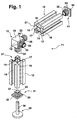
- the profile connection 11 shown in the drawing is made from rails 12 and the rails 12 together connectable connecting elements 13.
- the profile rails 12 are extruded from aluminum or one Made of aluminum alloy. These have an in Longitudinal direction of the rail 12 extending Through hole 14, also called core pull, with a square cross section. On an outer surface of the Through hole 14 are in the longitudinal direction Profile rail 12 extending T-shaped grooves 16 are provided.
- each Hollow channel 17 formed between the grooves 16 .
- the four T-shaped grooves 16 are exemplary embodiments evenly offset by 90 ° and open educated. Alternatively, it can be provided that one or several side surfaces of the rail 12 closed are trained. Furthermore, a plurality of grooves 16 be provided, which are optionally designed to be closed can. At the same time, the profile rail 12 can also be more Have cross sections.
- the connecting element 13 has, for example cuboid body 18, which as an injection molded part Plastic or made of aluminum or die-cast zinc is.
- the body 18 has a square cross section outer surfaces lying at right angles to one another 19.
- On the Outer surface 19 is in a longitudinal central axis of body 18 a pin 22 protruding from the outer surface 19 arranged.
- This has a square cross section, whose outer circumference is geometrically the cross section of the Through hole 14 corresponds.
- the spigot 22 have other geometric shapes that allow that the pin 22 can be pressed into the through hole 14.
- the pin 22 has two on its side surfaces 23 bump-shaped elevations 24, which are spaced apart are arranged. Alternatively, it can be provided that as well several surveys 24 are provided, which on one or several outer surfaces 23 are provided. These can be one cross-section deviating from the hump-shaped cross-section exhibit. Through these elevations 24 or ribs in assembled state with the profile rail 12 in the Through hole 14 a press fit can be achieved.
- the Elevations 24 advantageously have an oversize of 0.3 up to 0.5 mm compared to the inner diameter of the bore 14.
- the pin 22 in the Through hole 14 When connecting the rail 12 with the Connecting element 13, the pin 22 in the Through hole 14 inserted. Through the structured Side surface 23 of the pin 22 can be achieved that the Force required for a positive and positive connection not between the pin 22 and the through hole 14 gets high.
- the pin 22 of the connecting element 13 can for example by hammer blows into the through hole 14 of the rail 12 are driven. Because of the Excess of the surveys 24 is at least of these Slightly removed material, so that it leads to chip formation can come.
- the outer surface 19 points in the transition to the pin 22 a surrounding the pin 22 and designed as a chip space Well 26 on. This can be achieved that the Outer surface 19 flush with an end surface 27 of the Profile rail 13 can rest.
- the connecting element 13 shown in the exemplary embodiment has, for example, three pins 22, so that three by 90 ° staggered rails 12 can be attached are.
- the connecting element 13 can alternatively in one Plane of the cuboid body 18 one to four pins 22 exhibit.
- a T-shaped one Connector may be provided.
- everyone can any arrangement of one or more pins 22 on the cuboid body 18 may be given.
- a connecting element 31 is provided for receiving a support foot 34 is used.
- the pin 22 is on one plate-shaped element 32 provided and as a hollow body educated.
- a threaded sleeve 33 can be inserted therein be molded on.
- the support foot 34 is in this threaded sleeve 33 can be arranged with its threaded portion 36. This can cause a height-adjustable profile connection 11 can be created.
- the one facing the end face 27 Outer surface 19 also designed as a chip space Recess 26 provided.
- a cover cap 41 is shown at a rear end of the horizontal Profile rail 12. This allows protection for an end face 27 of the Profile rail 12.
- This cover cap 41 has plate-shaped element 42 on which a pin 22nd is arranged.
- the connecting element 31 and the cover cap 41 are analogous to the connecting element 13 to the end face 27 of the Profile rail 12 can be arranged and the example of the Connecting element 13 described advantageous Have configurations.
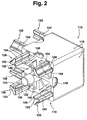
- FIGS. 2 and 3 are perspective views Representation of a connecting element 113 shown, which is designed as a corner connector, for example is.
- This connecting element 113 enables the arrangement of two arranged at 90 ° to each other Profile rails 112 (Fig. 4 and 5).
- the connecting element 113 has a protruding from a base 119 approximately round pin 122. This is exemplary as an N-corner or cylinder is formed. From the outer surface 119 seen up to the free end of the pin 122 can this be conical, towards the free end rejuvenated.
- the outer surface 119 assigned to the pin 122 is formed by a ribbing that has multiple openings having.
- the ribbing is formed by webs 146 which preferably a regular arrangement, such as 2 and 3 is shown.
- projections 128 which are axially parallel extend to the pin 122 from the outer surface 119.
- These projections 128 have a cross section that one T shape is approximated. This cross section enables that a good power transmission and torque transmission from that Connecting element 113 takes place on the profile rail 112, by also pressing these protrusions 128 into Engage hollow channels 117 of the profile rail 112.
- the shape of the Projections 128 match the cross-sectional shape of the hollow channels 117 customizable so that depending on the one used Profile rail 112, the projections 128 are formed.
- the connecting element 113 as Injection molded part is formed and the projections 128 and Pins 122 are integrally formed on the base body 118.
- the base body 118 holes for Includes the pin 122 and protrusions 128 so that only matched to the respective application the pin 122 or only two or more protrusions 128 or any combination of these to connect the Connecting element 113 with the rail 112 in the Body 118 can be used.
- the projections 128 are analogous to the pin 122 on their free End also tapered, which can be achieved can that a simple and quick attachment of the Connecting element 113 on the bore 114 and hollow channels 117 is made possible before, for example, with hammer blows a connection is created in which the outer surfaces 119 the profile rail 112 almost seamlessly into the outer surfaces 119 of the connecting element 113.
- a drive-in connector trained connecting element 113 has four closed and flat outer surfaces 119. On the side edges of the Outer surface 119 which receives a pin 122 The outer surface 119 adjoins are semicircular Indentations 148 are provided which open towards the connecting surface are trained. Between the two by 90 ° to each other offset 122 is a recess 149 provided that seen in cross section one Cross-sectional area of a groove 151 (Fig. 4 and Fig. 5) of the Profile rail 112 corresponds. This makes it possible for the use of such a profile connection in one four corner connectors 113 and at least four Profile rails 112, for example, a cutting disc can be used and recorded without the Corner areas of such a cutting disc or Separator must be edited.
- a corner connecting element 113 Optimized from an injection molding point of view be produced, which at the same time due to the Ribs a high force absorption and power transmission or has a high rigidity. Due to the half-timbered Ribs can tensile and compressive stresses as well as bending and Torsional moments are sufficiently absorbed.
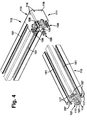
- FIG. 4 shows a profile connection 111 in which a profile rail 112 before assembly to the connecting element 113 and a profile rail 112 after assembly for Connecting element 113 is shown.
- FIG. 5 shows an alternative perspective view Fig. 4 shown, in which both rails 112 for Connecting element 113 are positioned. 4 is exemplified a profile rail 112, the one round through hole 114 with each other evenly spaced and radially inward-pointing webs having. Outside the through hole 114 are diagonal outwardly extending webs are provided, each one Wear hollow channel 117, which in the total cross section of the Profile rail 112 seen a square cross section forms. At the same time between the hollow channels 117 Groove 151 formed, which has a cross section for receiving a Hammer head screw or a sliding block or the like having.
- the function of the cross section of the projections 128 clearly.
- To the horizontal portion 153 of protrusions 128 are the free ones
- the ends are angled outwards, the contact surfaces 154 have. These run parallel to the outer surfaces of the base body 118 and lie flat on straight sections on the inside of the hollow channels 117.
- the vertical Section 156 is supported in a corner area 157 in the Hollow channel 117 from. This allows a positive and positive Connection created, which is also a Centering allows so that the outer surfaces of the Profile rail 112 in a plane to the outer surfaces 119 of the Connecting element 113 are arranged in the assembled state.
- the exemplary configuration of the connecting element 113 can also be applied to a connecting element 13, 31 in FIG. 1 be transmitted analogously.
- FIG. 6 to 8 is another alternative Embodiment shown in which the connecting element 213 is designed as a T-shaped impact connector.
- the Pin 222 and projections 228 are offset from one another by 90 ° arranged and lie in one plane.
- This allows the Profile rails 212 are arranged T-shaped to each other, such as for example, is shown in Fig. 8.
- the concrete one Design of the connecting element 212 corresponds in principle the connecting element 113.
- the profile rails 212 are with the profile rails 112 according to FIGS. 4 and 5 identically trained.
- connecting elements 13 and 113, 213 can be the number of each outer surface arranged pins on the respective application be coordinated.
- a pin can be provided on the outer surface.
- any arrangement and number of pins on the respective outer surfaces are provided, which the connection of the Profile rails enabled.
- it can be provided that depending on the cross-sectional shape of the profile rail one or more protrusions on the connecting element are arranged. These can also be according to their Cross-sectional shape on the profile cross-section of the profile rail be adjusted.
Landscapes
- Engineering & Computer Science (AREA)
- General Engineering & Computer Science (AREA)
- Mechanical Engineering (AREA)
- Mutual Connection Of Rods And Tubes (AREA)
Applications Claiming Priority (2)
| Application Number | Priority Date | Filing Date | Title |
|---|---|---|---|
| DE19647758 | 1996-11-19 | ||
| DE1996147758 DE19647758A1 (de) | 1996-11-19 | 1996-11-19 | Profilverbindung |
Publications (2)
| Publication Number | Publication Date |
|---|---|
| EP0843103A2 true EP0843103A2 (fr) | 1998-05-20 |
| EP0843103A3 EP0843103A3 (fr) | 1999-03-17 |
Family
ID=7812079
Family Applications (1)
| Application Number | Title | Priority Date | Filing Date |
|---|---|---|---|
| EP97114134A Withdrawn EP0843103A3 (fr) | 1996-11-19 | 1997-08-16 | Connection pour profilés. |
Country Status (2)
| Country | Link |
|---|---|
| EP (1) | EP0843103A3 (fr) |
| DE (1) | DE19647758A1 (fr) |
Cited By (6)
| Publication number | Priority date | Publication date | Assignee | Title |
|---|---|---|---|---|
| EP0993792A1 (fr) * | 1998-10-16 | 2000-04-19 | Octanorm-Vertriebs-Gmbh Für Bauelemente | Arrangement de profilés pour construire des dispositions de présentation et ou de magasins |
| WO2001077573A1 (fr) * | 2000-04-11 | 2001-10-18 | Profilgruppen Ab | Procede de fixation de barres lors du montage d'une structure cadre |
| DE19823229C2 (de) * | 1998-05-25 | 2003-04-30 | Hartmut Knell | Bauteilesystem zur Herstellung einer lösbaren Verbindung von Bauelementen |
| ITPD20090132A1 (it) * | 2009-05-13 | 2010-11-14 | Lasa S R L | Elemento strutturale per la realizzazione di complementi d'arredo tipo scrivanie, tavoli, pannelli e simili |
| WO2011095380A1 (fr) | 2010-02-05 | 2011-08-11 | Rotho Kunststoff Ag | Raccord angulaire, en particulier raccord angulaire pour systèmes de meubles modulaires |
| EP4036424A1 (fr) * | 2021-02-01 | 2022-08-03 | Schlüter-Systems KG | Système de profilé |
Families Citing this family (4)
| Publication number | Priority date | Publication date | Assignee | Title |
|---|---|---|---|---|
| CN103089770A (zh) * | 2013-02-13 | 2013-05-08 | 长沙洋华机电设备制造有限公司 | 一种铝型材的三通连接件 |
| DE202014106206U1 (de) * | 2014-12-22 | 2016-03-23 | Grass Gmbh | Verbindungsvorrichtung für eine als Hohlprofil ausgebildete Strebe in einem Möbelteil |
| DE202016004724U1 (de) | 2016-08-03 | 2017-11-06 | Isel Facility GmbH | Verbindungsvorrichtung |
| CN107989866A (zh) * | 2018-01-10 | 2018-05-04 | 芜湖智佳信息科技有限公司 | 一种自动售货机机箱用连接机构 |
Citations (5)
| Publication number | Priority date | Publication date | Assignee | Title |
|---|---|---|---|---|
| GB1123613A (en) * | 1964-10-30 | 1968-08-14 | Std Services Ltd | Jointing of tubes |
| US4161375A (en) * | 1978-05-05 | 1979-07-17 | Murphy Pierce M | Connector for tubes of square cross-section |
| US4354768A (en) * | 1981-05-01 | 1982-10-19 | Medalist Industries, Inc. | Tubing connector |
| WO1985002234A1 (fr) * | 1983-11-15 | 1985-05-23 | Rasmussen Gunnar Olaf Vesterga | Joint pour profiles creux |
| EP0384064A1 (fr) * | 1989-02-17 | 1990-08-29 | Miranda Investments Limited | Connecteurs à embouts pour l'assemblage de tuyaux polyédriques |
-
1996
- 1996-11-19 DE DE1996147758 patent/DE19647758A1/de not_active Withdrawn
-
1997
- 1997-08-16 EP EP97114134A patent/EP0843103A3/fr not_active Withdrawn
Patent Citations (5)
| Publication number | Priority date | Publication date | Assignee | Title |
|---|---|---|---|---|
| GB1123613A (en) * | 1964-10-30 | 1968-08-14 | Std Services Ltd | Jointing of tubes |
| US4161375A (en) * | 1978-05-05 | 1979-07-17 | Murphy Pierce M | Connector for tubes of square cross-section |
| US4354768A (en) * | 1981-05-01 | 1982-10-19 | Medalist Industries, Inc. | Tubing connector |
| WO1985002234A1 (fr) * | 1983-11-15 | 1985-05-23 | Rasmussen Gunnar Olaf Vesterga | Joint pour profiles creux |
| EP0384064A1 (fr) * | 1989-02-17 | 1990-08-29 | Miranda Investments Limited | Connecteurs à embouts pour l'assemblage de tuyaux polyédriques |
Cited By (9)
| Publication number | Priority date | Publication date | Assignee | Title |
|---|---|---|---|---|
| DE19823229C2 (de) * | 1998-05-25 | 2003-04-30 | Hartmut Knell | Bauteilesystem zur Herstellung einer lösbaren Verbindung von Bauelementen |
| EP0993792A1 (fr) * | 1998-10-16 | 2000-04-19 | Octanorm-Vertriebs-Gmbh Für Bauelemente | Arrangement de profilés pour construire des dispositions de présentation et ou de magasins |
| US6223917B1 (en) | 1998-10-16 | 2001-05-01 | Octanorm-Vertriebs-Gmbh Fuer Bauelemente | Profile arrangement for building exhibition or shop systems |
| EP1317893A2 (fr) | 1998-10-16 | 2003-06-11 | Octanorm-Vertriebs-Gmbh Für Bauelemente | Arrangement de profilés pour construire des dispositions de présentation ou de magasins |
| WO2001077573A1 (fr) * | 2000-04-11 | 2001-10-18 | Profilgruppen Ab | Procede de fixation de barres lors du montage d'une structure cadre |
| ITPD20090132A1 (it) * | 2009-05-13 | 2010-11-14 | Lasa S R L | Elemento strutturale per la realizzazione di complementi d'arredo tipo scrivanie, tavoli, pannelli e simili |
| WO2011095380A1 (fr) | 2010-02-05 | 2011-08-11 | Rotho Kunststoff Ag | Raccord angulaire, en particulier raccord angulaire pour systèmes de meubles modulaires |
| EP4036424A1 (fr) * | 2021-02-01 | 2022-08-03 | Schlüter-Systems KG | Système de profilé |
| US20220243747A1 (en) * | 2021-02-01 | 2022-08-04 | Schluter Systems, LP | Profile System for Intersecting Joints |
Also Published As
| Publication number | Publication date |
|---|---|
| DE19647758A1 (de) | 1998-05-20 |
| EP0843103A3 (fr) | 1999-03-17 |
Similar Documents
| Publication | Publication Date | Title |
|---|---|---|
| EP1259738B1 (fr) | Dispositif de connexion de profiles | |
| EP0747603B1 (fr) | Assemblage pour panneaux | |
| EP0662200B1 (fr) | Dispositif pour relier au moins deux elements | |
| DE4142273C2 (de) | Vorrichtung zum lösbaren Verbinden von zwei in einer Ebene senkrecht aufeinanderstehenden Strebenprofilen | |
| DE1575197A1 (de) | Profilschienen-Verbindung | |
| DE4210456A1 (de) | Querverbindung für Profilstäbe mittels Zuggliedern | |
| EP1729018B1 (fr) | Système d'assemblage de profilés | |
| EP1141562B1 (fr) | Dispositif d'assemblage permettant de reunir une premiere piece a une seconde | |
| EP0843103A2 (fr) | Connection pour profilés. | |
| DE10146492B4 (de) | Verbindungselement für Profile | |
| EP1205676B1 (fr) | Unité de montage constituée d'un composant et d'au moins une vis | |
| DE102005013364A1 (de) | Positionsmesseinrichtung | |
| EP0846874B1 (fr) | Commutateur de cylindre | |
| DE102005058386A1 (de) | Pfosten-Riegel-Verbindung | |
| EP2627915B1 (fr) | Dispositif d'ancrage destiné à fixer une pièce sur un élément de support | |
| EP0267161A2 (fr) | Dispositif de vissage | |
| DE19806922C1 (de) | Querverbinder für mit hinterschnittenen Längsnuten versehene stranggezogene Hohlprofilstäbe | |
| DE202007014791U1 (de) | Hubsäule | |
| EP1276996A1 (fr) | Unite de montage constituee d'un composant et d'au moins une vis taraudeuse | |
| EP0423474B1 (fr) | Dispositif pour relier deux baguettes profilées de façon à ce qu'elles soient détachables | |
| EP3173556A1 (fr) | Élément de montage destiné à fixer des pentures de porte | |
| EP1227251A1 (fr) | Profilé à contre-dépouille | |
| DE102017126456A1 (de) | Eckverbinder | |
| EP1335138B1 (fr) | Attache pour barre profilée | |
| EP0903505A1 (fr) | Elément pour la fixation dans une cavité d'un profilé creux ou pièce semblable |
Legal Events
| Date | Code | Title | Description |
|---|---|---|---|
| PUAI | Public reference made under article 153(3) epc to a published international application that has entered the european phase |
Free format text: ORIGINAL CODE: 0009012 |
|
| AK | Designated contracting states |
Kind code of ref document: A2 Designated state(s): CH DE FR IT LI |
|
| PUAL | Search report despatched |
Free format text: ORIGINAL CODE: 0009013 |
|
| AK | Designated contracting states |
Kind code of ref document: A3 Designated state(s): AT BE CH DE DK ES FI FR GB GR IE IT LI LU MC NL PT SE |
|
| 17P | Request for examination filed |
Effective date: 19990917 |
|
| AKX | Designation fees paid |
Free format text: CH DE FR IT LI |
|
| 17Q | First examination report despatched |
Effective date: 19991223 |
|
| STAA | Information on the status of an ep patent application or granted ep patent |
Free format text: STATUS: THE APPLICATION IS DEEMED TO BE WITHDRAWN |
|
| 18D | Application deemed to be withdrawn |
Effective date: 20010207 |