EP0842008B1 - Schweisslinie mit datenspeichervorrichtung zur qualitätskontrolle - Google Patents
Schweisslinie mit datenspeichervorrichtung zur qualitätskontrolle Download PDFInfo
- Publication number
- EP0842008B1 EP0842008B1 EP96923682A EP96923682A EP0842008B1 EP 0842008 B1 EP0842008 B1 EP 0842008B1 EP 96923682 A EP96923682 A EP 96923682A EP 96923682 A EP96923682 A EP 96923682A EP 0842008 B1 EP0842008 B1 EP 0842008B1
- Authority
- EP
- European Patent Office
- Prior art keywords
- parts
- signal
- containment box
- production line
- control system
- Prior art date
- Legal status (The legal status is an assumption and is not a legal conclusion. Google has not performed a legal analysis and makes no representation as to the accuracy of the status listed.)
- Expired - Lifetime
Links
- 238000003466 welding Methods 0.000 title claims description 47
- 238000003908 quality control method Methods 0.000 title 1
- 238000012360 testing method Methods 0.000 claims description 78
- 238000004519 manufacturing process Methods 0.000 claims description 63
- 238000007689 inspection Methods 0.000 claims description 46
- 238000000034 method Methods 0.000 claims description 36
- 230000002950 deficient Effects 0.000 claims description 34
- 238000006073 displacement reaction Methods 0.000 claims description 24
- 239000003550 marker Substances 0.000 claims description 7
- 238000012790 confirmation Methods 0.000 claims description 4
- 230000004044 response Effects 0.000 claims description 4
- 238000001514 detection method Methods 0.000 claims description 3
- 238000000151 deposition Methods 0.000 claims description 2
- 238000004891 communication Methods 0.000 claims 3
- 238000005259 measurement Methods 0.000 claims 2
- 230000007547 defect Effects 0.000 claims 1
- 238000012795 verification Methods 0.000 claims 1
- 238000010586 diagram Methods 0.000 description 9
- 230000008569 process Effects 0.000 description 4
- 238000003780 insertion Methods 0.000 description 3
- 230000037431 insertion Effects 0.000 description 3
- 230000008439 repair process Effects 0.000 description 3
- 239000008188 pellet Substances 0.000 description 2
- 238000010276 construction Methods 0.000 description 1
- 230000003111 delayed effect Effects 0.000 description 1
- 230000001066 destructive effect Effects 0.000 description 1
- 238000011156 evaluation Methods 0.000 description 1
- 230000001747 exhibiting effect Effects 0.000 description 1
- 238000010348 incorporation Methods 0.000 description 1
- 238000003754 machining Methods 0.000 description 1
- 230000007246 mechanism Effects 0.000 description 1
- 239000003758 nuclear fuel Substances 0.000 description 1
- 230000003287 optical effect Effects 0.000 description 1
- 239000003973 paint Substances 0.000 description 1
- 230000000737 periodic effect Effects 0.000 description 1
- 238000013031 physical testing Methods 0.000 description 1
- 230000000717 retained effect Effects 0.000 description 1
- 238000010079 rubber tapping Methods 0.000 description 1
- 238000011179 visual inspection Methods 0.000 description 1
Images


Classifications
-
- B—PERFORMING OPERATIONS; TRANSPORTING
- B23—MACHINE TOOLS; METAL-WORKING NOT OTHERWISE PROVIDED FOR
- B23K—SOLDERING OR UNSOLDERING; WELDING; CLADDING OR PLATING BY SOLDERING OR WELDING; CUTTING BY APPLYING HEAT LOCALLY, e.g. FLAME CUTTING; WORKING BY LASER BEAM
- B23K11/00—Resistance welding; Severing by resistance heating
- B23K11/24—Electric supply or control circuits therefor
- B23K11/25—Monitoring devices
- B23K11/252—Monitoring devices using digital means
- B23K11/253—Monitoring devices using digital means the measured parameter being a displacement or a position
-
- B—PERFORMING OPERATIONS; TRANSPORTING
- B23—MACHINE TOOLS; METAL-WORKING NOT OTHERWISE PROVIDED FOR
- B23K—SOLDERING OR UNSOLDERING; WELDING; CLADDING OR PLATING BY SOLDERING OR WELDING; CUTTING BY APPLYING HEAT LOCALLY, e.g. FLAME CUTTING; WORKING BY LASER BEAM
- B23K11/00—Resistance welding; Severing by resistance heating
- B23K11/36—Auxiliary equipment
-
- G—PHYSICS
- G01—MEASURING; TESTING
- G01N—INVESTIGATING OR ANALYSING MATERIALS BY DETERMINING THEIR CHEMICAL OR PHYSICAL PROPERTIES
- G01N21/00—Investigating or analysing materials by the use of optical means, i.e. using sub-millimetre waves, infrared, visible or ultraviolet light
- G01N21/84—Systems specially adapted for particular applications
- G01N21/88—Investigating the presence of flaws or contamination
-
- G—PHYSICS
- G07—CHECKING-DEVICES
- G07C—TIME OR ATTENDANCE REGISTERS; REGISTERING OR INDICATING THE WORKING OF MACHINES; GENERATING RANDOM NUMBERS; VOTING OR LOTTERY APPARATUS; ARRANGEMENTS, SYSTEMS OR APPARATUS FOR CHECKING NOT PROVIDED FOR ELSEWHERE
- G07C3/00—Registering or indicating the condition or the working of machines or other apparatus, other than vehicles
Definitions
- This invention relates to a system and apparatus for storing defective parts.
- defective parts are manufactured. It is important to identify and remove these defective parts and ensure that they remain segregated from good parts so that they are not subsequently incorporated into a finished article sold to a consumer or used. It is advantageous to identify defective parts as soon as possible so that those parts can be removed from the production line before additional expenses associated with further machining or assembly are incurred and prior to incorporation of the defective part into a larger assembly.
- One of the problems that the present invention solves is that machine operators frequently incorrectly assume that the automatic parts inspection operation committed an error when a part which looks perfectly good is rejected. On occasion, operators will pass the rejected part, as opposed to removing the part from the production line, which ultimately causes defective parts to be incorporated into finished goods. Inclusion of defectively welded parts into a production vehicle, for example, can result in expensive warranty repairs or product recall. On some occasions, the defectively welded part will fail during a subsequent manufacturing operation and will not even make it out of the plant. For example, weld nuts which are improperly attached to an assembly may subsequently break off during the nut tapping process or when a fastener is subsequently attached. If the product incorporating the weld nut is in an advance stage of assembly, the cost and expense for repairing a defectively welded part can be significant.
- Yet another object of the present invention is to provide a method and apparatus which forecloses the possibility of a situation occurring where a part identified as being defective is passed on as a good part by the production operator who, with good intentions after a visual inspection, incorrectly believes that the part is not defective.
- Another object of the present invention is to provide a method and apparatus for identifying parts exhibiting a predetermined characteristic at a production line inspection station which requires the identified part to be removed and securely stored prior to resuming operation of the production line.
- a control system for a production line having a production line drive and an inspection station wherein the production line is adapted to index a plurality of parts to the inspection station for identifying parts having a specific predetermined characteristic, the control system comprising:
- a specific embodiment of the present invention is provided for use in a production line including a resistance welding station having a weld gun with a displaceable welding electrode.
- the production line is adapted when driven to index a plurality of parts to the resistance welding station for welding the parts together as the electrode is displaced relative to the parts.
- the control system includes a displacement sensor coupled to the welding electrode for generating a displacement sensor signal responsive to the displacement of the welding electrode relative to the parts as the parts are being welded.
- a part containment box for receiving improperly welded parts is also provided.
- the part containment box has an input sensor which generates an input sensor signal when an improperly welded part enters the part containment box.
- a test computer is coupled to the displacement sensor, the input sensor of the part containment box, and the production line drive. The test computer evaluates the displacement sensor signal to identify parts which are improperly welded whereupon a fault signal is generated disabling the indexing of the production line drive until the input sensor signal is received indicating that the improperly welded part has been removed from the resistance welding station and deposited into the part containment box.
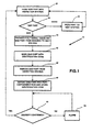
- FIGS 1 and 2 illustrate a method block diagram 10 in a control system 12 utilized for practicing the present invention.
- the control system 12 of the present invention is utilized in conjunction with a production line 14 which includes an inspection station 16 and an immediately adjacent previous station 18 and an immediately adjacent subsequent station 20.
- a programmable logic controller (PLC) 22 regulates the indexing of parts from station to station. Parts are routinely transferred from previous station 18 into inspection station 16 where the parts are inspected and, upon satisfactorily passing the inspection, are transferred to subsequent station 20.
- inspection station 16 will also provide a concurrent functional operation, such as welding or forming the part, as the inspection operation is being conducted.
- test sensor 24 is provided for inspecting a measured parameter of the part in inspection station 16.
- Test sensor 24 provides a test sensor signal responsive to the inspected parameter.
- the test sensor signal is provided to test computer 26 which conducts an analysis to determine whether the measured parameter is within a predetermined range. In the preferred embodiment illustrated in Figures 1 and 2, if the test computer 26 indicates that the part is good, PLC 22 will cause the parts to index from station to station transferring the inspected part from station 16 to subsequent station 18 and transferring a new part from previous station 18 into inspection station 16 whereupon the process will be repeated.
- test computer 26 With reference to the method block diagram 10 shown in Figure 1, the first step is illustrated in block 28 which indexes a new part into the inspection station 16. The part is then tested in block 30. Good parts are indexed to the next station illustrated by block 32. If test computer 26 indicates that the part is bad, then test computer 26 will provide a fault signal disabling the part from indexing to the next station as illustrated by block 34. Test computer 26 is coupled to the PLC 22 which in turn inhibits production line movement. Optionally, a part marker 36 (illustrated in Figure 2) is provided to appropriately identify the bad parts so that subsequently they may be monitored and evaluated.
- the part marker 36 can be as simple as merely marking the bad part with a dot of paint or, alternatively, the part marker 36 could apply a bar code having indicia indicating date and time, part number, and the nature of the fault detected.
- the test computer 26 upon sensing the occurrence of a bad part will provide a brief alarm signal to the machine operator via alarm 38 (shown in Figure 2).
- Logic can be added to limit the maximum number of bad parts which can be made within a set prior to shutting down.
- the step of marking a bad part with an identification code is provided in block 40.
- the step of marking the part is optional. In some applications, good parts will be marked or identified as explained below.
- test computer will keep track of the bad part and delay the step for providing a fault signal until the part is at a station in which it can be removed by an operator or robot, whereupon a delayed fault signal will be provided requiring the operator to remove the failed part and place it in the failed part containment box as previously described.
- a test for confirming delivery shown in block 50 is provided within the test computer 26 in response to the input sensor signal generated by input sensor 46. If delivery of the defective part is confirmed within a predetermined time period, production resumes and the previously described sequence of the method steps takes place with a new part being indexed into the inspection station 16 as illustrated by block 28 in method block diagram 10. In the event that the delivery of the defective part to the failed part containment box 44 is not confirmed within the predetermined time period, an alarm signal is provided as illustrated by block 52.
- failed part containment box 44 is provided with an input door 54 as shown in Figure 2.
- Input door 54 is normally locked when the production line 14 is running.
- Input door 54 seals the part containment box 44 for preventing the input or the withdrawal of parts contained therein.
- a fault signal is generated which disables the production line 14 and unlocks the input door 54.
- the operator then removes the defective part from the inspection station and is allowed access to place it into the failed part containment box 44 through the unlocked input door 54.
- the input sensor 46 detecting the deposit of a failed part, the input sensor signal is transmitted to the test computer 46 which causes input door 54 to lock and the production line 14 is enabled.
- Failed part containment box 44 is also provided with a part removal door 62 for allowing the removal of the defective parts therein by an authorized user.
- the control system 12 is used with a multi-station conventional production line in which defective parts are an infrequent occurrence.
- the defective parts are deposited in part containment box 44.
- This method is also adaptable to sorting systems in which parts or objects are being transferred along a production line having an inspection station where the system is used to sort out good parts having a predetermined characteristic from a group of parts which are predominantly bad.
- the part containment box is provided for receiving the parts identified as good, rather than bad.
- the part containment box is provided with an input sensor for generating an input sensor signal when a good part is placed into the part containment box.
- the test computer is coupled to the test sensor, the input sensor of the part containment box, and the production line.
- the test computer evaluates the test sensor signal to determine whether or not the part being measured in the inspection station has the predetermined characteristic.
- a signal is provided which disables the indexing of the production line until the input sensor signal is received indicating that the good part has been removed from the inspection station and deposited into the part containment box.
- the method of the present invention and the associated control system while illustrated in the drawings in association with a resistance welding production line, is useful in a variety of non-welding applications.
- the system is particularly useful where it is difficult to visually inspect parts, especially in instances when the problems associated with the failure to promptly detect a failed part are significant as in the case of many safety-related components of consumer products, motor vehicles, or aircraft.
- the inspection operation could be utilized to inspect electronic devices such as circuit boards or the like prior to insertion into a finished product.
- the method and apparatus of the present invention provide a secure and safe way of handling parts identified as defective or acceptable, depending on the application, to ensure that they are not inadvertently passed on to a customer.
- test computer 26 could be integrated into PLC 22 if desired.
- test computer 26 could be utilized to control inspection station 16.
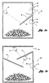
- Figure 3a illustrates part containment box 44 in cut-away side elevation.
- part containment boxes can be made of a variety of shapes and sizes dictated in large part by the size of the parts to be stored therein.
- the box is of similar size and configuration to a U.S. Mail Deposit box.
- Input door 54 is pivotally attached to box 44 and shifted between a closed position illustrated and an opened position shown in phantom outline.
- input door 54 is provided with an inner member 56, rigidly attached to input door 54 at an angle ⁇ , similar to a U.S. Mail box door, which partially obscures the door opening to prevent the removal of parts from within the interior of part containment box 44.
- a remotely controlled lock assembly 58 is provided inside part containment box 44 for locking input door 54 in the closed position during normal operation.
- Sensor 46 is located in the interior of the part containment box 44 and is positioned to sense the deposit of a part into the part containment box 44.
- Sensor 46 is preferably an optical sensor, but could also be a non-contact proximity switch, sensor, or the like.
- the part containment box 44 is sized according to the parts to be stored and could be as large as a room size enclosure capable of storing entire car bodies.
- the failed part containment box 44 is provided with an internal slide baffle 60 which is downwardly inclined and mounted adjacent to input door 54. Parts deposited in the box slide down slide baffle 60 and are sensed by input sensor 46 before falling into the bottom of box 44. Part removal door 62 is located in the lower region of box 44 to facilitate part removal. Part removal door 62 is locked by a lock sensor combination 64. Lock sensor 64 cooperates with the test computer 26. In order for an operator to remove parts from the failed part containment box 44, an appropriate authorized user code must be entered in the test computer 26. Test computer 26 then causes lock sensor 64 to release part removal door 62. Test computer 26 will make an appropriate recording of time and date and authorized user code whenever part containment box 44 is accessed either through part removal door 62 or input door 54.
- lock sensor 64 will also provide a door open signal to test computer 26 requiring part removal door 62 to be securely locked prior to the resumption of the indexing of the parts and to provide a tamper signal in the event that the part removal door 62 is forced open without entry of the authorized user code.
- Lock sensor 64 and lock assembly 58 are preferably of similar construction, both capable of locking the respective doors closed securely in response to test computer 26 while also providing an input signal to test computer 26 indicative of door opened or closed status.
- Figure 3b illustrates an alternative part containment box embodiment 66.
- Part containment box 66 is provided with an open inlet chute 68 for insertion of marked parts.
- Inlet chute 68 is preferably sized to receive the desired parts while limiting the deposit of larger or differently shaped parts.
- Part containment box 66 is further provided with a pair of slide baffles 70 and 72 along which incoming parts will cascade. Located adjacent each slide baffle 70 and 72 is a part sensor 74 and 76 to detect the insertion of a failed part.
- Part containment box 66 is also provided with an outlet door 78 having a combination door/lock sensor 80 functioning in the manner described with reference to part removal door 62 and lock sensor 64 in the Figure 3a embodiment.
- FIG. 4 illustrates a resistance welding production line 82 having a resistance welding station 84, a previous station 86, and a subsequent station 88.
- a part 90 is transferred into the welding station 84 where a weld nut 92 will be welded to the part 90 by weld gun 94.
- Weld nut 92 is fed into the welding station 84 by a pole feeder 96 and is placed onto the part 90 to be welded by an appropriate pick and place device 98.
- the weld gun 94 is provided with a displaceable conventional welding electrode 100 which is displaceable relative to the part 90 as weld nut 92 is welded thereto.
- Displacement sensor 102 is coupled to the welding electrode 100 and generates a displacement sensor signal responsive to the displacement of the welding electrode 100 relative to the parts being welded together.
- the displacement sensor signal is provided to test computer 104 which compares the displacement sensor signal to a predetermined desired displacement profile.
- test computer 104 communicates with a PLC 106 which controls the operation of a production line drive 108.
- Test computer 104 also cooperates with a part marker 110 in order to mark defective parts.
- the test computer 26 will cooperate with the clamps 112' and 112'' in order to release the part 90 to enable the system operator to remove the identified part prior to deposit in a part containment box 114.
- part containment box 114 may be provided with a compactor 116.
- Compactor 116 may be part of the box or an adjacent component.
- compactor 116 may be an adjacent accessory which is used to destroy parts determined to be unrepairable after inspection.
- Compactor 116 is preferably coupled to test computer 104 so that data regarding the ultimate disposition of the parts can be recorded.
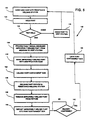
- Figure 5 illustrates a method block diagram 120 associated with the resistance welding production line 82 of Figure 4.
- Method block diagram 120 is similar to a more detailed version of method block diagram 10 shown in Figure 1.
- Method block 120 begins with the step of indexing new parts into a resistance weld station, as shown in block 122. The parts are welded together in block 124 and as they are being welded, the weld is tested and a post-weld or real-time good or bad weld determination is made in block 126. In the event a good weld is made, the good part is indexed to the next station as shown in block 128. If a bad weld is made, the test computer provides a fault signal disabling the improperly welded part from indexing to the next station as shown in block 130.
- the test computer will signal a part marker to mark improperly welded parts with an identification code as shown in block 132. If a locked part containment box is utilized, the test computer will provide a signal unlocking the failed part containment box as shown in block 134 and if the part is retained in the welding station by fixture and/or the welding electrode, the test computer will cause the part to be released from the fixture as shown in block 136. The machine operator can then remove the improperly welded part from the fixture as shown in block 138. The machine operator or robot must then deposit the improperly welded part into the failed part containment box, block 140, and the delivery of the failed part is confirmed automatically by the input sensor located within the failed part containment box as evidenced by the delivery confirmed test shown schematically in block 142. In the event the locked failed part containment box is utilized, the box is again automatically locked, as shown in block 144. The test computer then reenables the production line allowing the indexing of a new part into the resistance welding station in block 122.
- Figure 6 illustrates a method of inspection 146 of failed parts which have been deposited in the failed part containment box.
- the initial block 148 illustrates the step of opening the failed part containment box by entering an authorized user code into the test computer. Once the box is opened, the operator removes parts from the failed part containment box at step 150 to account for all of the failed parts produced subsequent to the last box inspection as represented by block 152.
- the test computer is capable of generating a list of defective parts deposited in the failed part containment box in a test computer log report.
- the system will generate a report of missing parts and identify missing parts by part number, time and date made and report any prior access, authorized or not, to the containment box and provide access user codes, as illustrated in box 154.
- the parts present in the part containment box are then inspected to determine the nature of the fault and part repairability in step 156.
- Parts determined not to be repairable are destroyed in step 158 and repairable parts are transferred to a repair station 160.
- the nature of the repair will be accordingly dictated by the type of part and the nature of the fault.
Landscapes
- Engineering & Computer Science (AREA)
- Mechanical Engineering (AREA)
- Physics & Mathematics (AREA)
- General Physics & Mathematics (AREA)
- Health & Medical Sciences (AREA)
- Life Sciences & Earth Sciences (AREA)
- Chemical & Material Sciences (AREA)
- Analytical Chemistry (AREA)
- Biochemistry (AREA)
- General Health & Medical Sciences (AREA)
- Immunology (AREA)
- Pathology (AREA)
- General Factory Administration (AREA)
- Automatic Assembly (AREA)
Claims (22)
- Steuersystem (12) für eine Fertigungsstraße (82) mit einem Fertigungsstraßenantrieb (108) und einer Inspektionsstation (16), wobei die Fertigungsstraße dafür ausgelegt ist, eine Vielzahl von Teilen (90) für die Inspektionsstation zu indexieren, um Teile mit einer spezifischen vorherbestimmten Eigenschaft zu identifizieren, wobei das Steuersystem Folgendes umfasst:einen Testsensor (102), der mit der Inspektionsstation verbunden ist, um ein Testsensorsignal zu erzeugen, das auf eine Eigenschaft eines Teils reagiert, das in der Inspektionsstation gemessen wird;einen Teileaufnahmebehälter (114) zum Aufnehmen identifizierter Teile;einen Eingabesensor (46) zum Erzeugen eines Eingabesensorsignals, wenn ein identifiziertes Teil in den Teileaufnahmebehälter eintritt; undeinen Testcomputer (104), der mit dem Testsensor (102), dem Eingabesensor (46) und dem Fertigungsstraßenantrieb (108) verbunden ist, wobei der Testcomputer so betrieben werden kann, dass er das Testsensorsignal mit der vorherbestimmten Eigenschaft vergleicht, um Teile mit der vorherbestimmten Eigenschaft zu identifizieren und ein Fehlersignal zu erzeugen, das das Indexieren auf der Fertigungsstraße desaktiviert, bis das Eingabesensorsignal empfangen wird, das anzeigt, dass das identifizierte Teil aus der Inspektionsstation entfernt und in dem Teileaufnahmebehälter (114) abgelegt worden ist.
- Steuersystem nach Anspruch 1, das des Weiteren einen programmierbaren Logikkontroller (PLC) (106) umfasst, der mit dem Testcomputer (104) zusammenarbeitet und mit dem Fertigungsstraßenantrieb (108) verbunden ist, um das Indexieren der Fertigungsstraße (82) zu desaktivieren.
- Steuersystem nach Anspruch 1 oder 2, das des Weiteren eine Markierungsvorrichtung (110) umfasst, die auf den Testcomputer (104) anspricht, um die identifizierten Teile mit einem Identifikationscode zu markieren, bevor sie in dem Teileaufnahmebehälter abgelegt werden.
- Steuersystem nach einem der Ansprüche 1 bis 3, wobei die spezifische vorherbestimmte Eigenschaft einen Parameter eines Teils umfasst, das an der Inspektionsstation gemessen wird, der Testcomputer das Testsensorsignal mit einer gewünschten Parametermessung vergleicht, um defekte Teile zu identifizieren, die identifizierten Teile Parametermessungen aufweisen, die die Defekte bezeichnen, und der Eingabesensor in dem Teileaufnahmebehälter angeordnet ist.
- Steuersystem nach Anspruch 4, wobei die Markierungsvorrichtung (110) mit der Inspektionsstation verbunden ist.
- Steuersystem nach Anspruch 4 oder 5, wobei der Testcomputer (104) den Identifikationscode speichert, um eine Überprüfung zu ermöglichen, ob sich alle defekten Teile in dem Teileaufnahmebehälter befinden.
- Steuersystem nach einem der Ansprüche 4 bis 6, wobei der Teileaufnahmebehälter (44) eine Tür (54) aufweist, die zwischen einer geschlossenen Position zur Verweigerung des Eintritts in den Teileaufnahmebehälter und einer geöffneten Position zur Ermöglichung des Eintritts von defekten Teilen in den Teileaufnahmebehälter bewegt werden kann.
- Steuersystem nach Anspruch 7, wobei der Teileaufnahmebehälter des Weiteren eine erste Verriegelungsbaugruppe (58) umfasst, die mit dem Testcomputer (104) zusammenarbeitet, um bei Empfang des Fehlersignals die Tür zu entriegeln und die Tür in der geschlossenen Position zu verriegeln, nachdem der Testcomputer das Eingabesensorsignal empfangen hat.
- Steuersystem nach Anspruch 7 oder 8, wobei der Teileaufnahmebehälter (44) des Weiteren einen Tür-offen-Sensor umfasst, um dem Testcomputer ein Tür-offen-Signal bereitzustellen, wenn die Tür in die geöffnete Position bewegt wird, um dem Testcomputer zu ermöglichen, den Zugriff auf den Teileaufnahmebehälter zu überwachen.
- Steuersystem nach einem der Ansprüche 7 bis 9, wobei der Teileaufnahmebehälter des Weiteren eine Teileentnahmetür (62) umfasst, um die Entnahme defekter Teile daraus zu ermöglichen, die Teileentnahmetür eine zweite Verriegelungsbaugruppe (64) aufweist, die auf den Testcomputer (104) reagiert, um die Teileentnahmetür zu verriegeln und zu entriegeln, wobei die zweite Verriegelungsbaugruppe mit dem Testcomputer zusammenarbeitet, um die Teileentnahmetür bei Eingabe eines autorisierten Benutzercodes in den Testcomputer zu entriegeln.
- Steuersystem nach einem der Ansprüche 4 bis 10, das des Weiteren eine Pressvorrichtung (116) umfasst, die auf den Testcomputer (104) und den Teileaufnahmebehälter (44) reagiert, um die defekten Teile zu vernichten.
- Steuersystem nach einem der Ansprüche 1 bis 11, wobei das Steuersystem für eine Fertigungsstraße bestimmt ist, die eine Widerstandsschweißstation (84) aufweist, welche eine Schweißpistole (94) mit einer beweglichen Schweißelektrode (100) und einem Bewegungssensor (102) umfasst, der mit der Elektrode verbunden ist, um ein Bewegungssensorsignal zu erzeugen, das auf die Bewegung der Elektrode während des Schweißens reagiert, wobei die Widerstandsschweißstation dafür ausgelegt ist, eine Vielzahl von Teilen (90, 92) zusammenzuschweißen, wobei der Eingabesensor ein Eingabesensorsignal erzeugt, das auf die Erfassung eines unsachgemäß geschweißten Teils reagiert, der Testcomputer in Kommunikation mit dem Bewegungssensor und der Widerstandsschweißstation steht und so betrieben werden kann, dass er das Bewegungssensorsignal mit einem vorherbestimmten gewünschten Bewegungssignal vergleichen kann, um das unsachgemäß geschweißte Teil zu identifizieren, und das Fehlersignal die Widerstandsschweißstation desaktiviert, bis das Eingabesensorsignal empfangen wurde, das anzeigt, dass das unsachgemäß geschweißte Teil in dem Teileaufnahmebehälter abgelegt wurde.
- Steuersystem nach einem der Ansprüche 1 bis 11, wobei das Steuersystem für eine Fertigungsstraße bestimmt ist, die eine Widerstandsschweißstation (84) aufweist, die eine Schweißpistole (94) mit einer beweglichen Schweißelektrode (100) und einem Bewegungssensor ( 102) umfasst, der mit der Elektrode verbunden ist, um ein Bewegungssensorsignal zu erzeugen, das auf die Bewegung der Elektrode während des Schweißens reagiert, wobei die Widerstandsschweißstation dafür ausgelegt ist, eine Vielzahl von Teilen (90, 92) zusammenzuschweißen, wobei der Eingabesensor ein Eingabesensorsignal erzeugt, das auf die Erfassung eines unsachgemäß geschweißten Teils reagiert, der Testcomputer in Kommunikation mit dem Bewegungssensor steht und so betrieben werden kann, dass er das Bewegungssensorsignal mit einem vorherbestimmten gewünschten Bewegungssignal vergleicht und das Fehlersignal bereitstellt.
- Steuersystem nach Anspruch 11, wobei der Testcomputer (104) beim Identifizieren des unsachgemäß geschweißten Teils einer Fertigungsstraßenbedienungsperson ein Benachrichtigungssignal bereitstellt, um das unsachgemäß geschweißte Teil aus der Widerstandsschweißstation (84) zu entfernen und das Teil im Teileaufnahmebehälter (114) abzulegen.
- Steuersystem nach Anspruch 11 oder 12, wobei die Widerstandsschweißstation (84) des Weiteren eine Befestigung in Kommunikation mit dem Testcomputer umfasst, um die Teile während des Schweißens in der Widerstandsschweißstation zu befestigen und unsachgemäß geschweißte Teile freizugeben.
- Steuersystem nach einem der Ansprüche 11 bis 13, das des Weiteren eine Pressvorrichtung (116) umfasst, die auf den Testcomputer (104) reagiert, um die unsachgemäß geschweißten Teile zu vernichten.
- Steuersystem nach einem der Ansprüche 11 bis 14, das des Weiteren einen Alarm umfasst, der auf den Testcomputer reagiert, um in dem Fall, dass das Eingabesensorsignal in einem vorherbestimmten Zeitraum nach Empfang des Fehlersignals nicht empfangen wurde, ein Alarmsignal zu erzeugen.
- Steuerverfahren für eine Fertigungsstraße (14) mit einem Fertigungsstraßenantrieb und einer Inspektionsstation (16), wobei die Fertigungsstraße dafür ausgelegt ist, mindestens eins von einer Vielzahl von Teilen (90) in die und daraufhin aus der Inspektionsstation (16) heraus zu indexieren, wobei das Steuerverfahren Folgendes umfasst:Erzeugen eines Signals, das auf einen gemessenen Parameter eines Teils in der Inspektionsstation reagiert;Vergleichen des Signals (30) mit einem vorherbestimmten gewünschten Wert, um zu bestimmen, ob das Teil mit einem vorherbestimmten Profil übereinstimmt;dem Fertigungsstraßenantrieb ein Fehlersignal (34) bereitzustellen, das bei Identifikation eines mit dem Profil übereinstimmenden Teils das Indexieren der Fertigungsstraße desaktiviert;Entfernen des mit dem Profil übereinstimmenden Teils (42) aus der Inspektionsstation (16) und Ablegen des Teils in einem Teileaufnahmebehälter (48); undbei Empfang des mit dem Profil übereinstimmenden Teils in dem Teileaufnahmebehälter dem Fertigungsstraßenantrieb ein Bestätigungssignal (50) bereitzustellen, das das Indexieren der Fertigungsstraße ermöglicht.
- Steuerverfahren nach Anspruch 18, das des Weiteren folgende Schritte umfasst:Markieren des mit dem Profil übereinstimmenden Teils (40) mit einem Identifikationscode; undSpeichern des Identifikationscodes (48) zur Überprüfung, ob das mit dem Profil übereinstimmende Teil in dem Teileaufnahmebehälter abgelegt wurde.
- Steuerverfahren nach Anspruch 18 oder 19, das des Weiteren den Schritt des Erzeugens eines Alarmsignals (52) in dem Fall umfasst, dass das Bestätigungssignal nicht in einem vorherbestimmten Zeitraum erzeugt wird, nachdem das Fehlersignal erzeugt worden ist.
- Steuerverfahren nach einem der Ansprüche 18 bis 20, das des Weiteren folgende Schritte umfasst:Entriegeln des Teileaufnahmebehälters (44) als Reaktion auf das Fehlersignal; undVerriegeln des Teileaufnahmebehälters als Reaktion auf das Bestätigungssignal.
- Steuerverfahren nach einem der Ansprüche 18 bis 21, wobei die Inspektionsstation eine Schweißstation (84) zum Schweißen von Teilen umfasst, wobei das Erzeugen eines Signals das Erzeugen eines Signals umfasst, das auf die Schweißqualität geschweißter Teile reagiert, und das Vergleichen des Signals das Vergleichen des Signals mit einem vorherbestimmten gewünschten Wert umfasst, um unsachgemäß geschweißte Teile zu identifizieren.
Applications Claiming Priority (3)
| Application Number | Priority Date | Filing Date | Title |
|---|---|---|---|
| US498776 | 1990-03-26 | ||
| US08/498,776 US5614109A (en) | 1995-07-05 | 1995-07-05 | Welding line with quality control storage devices |
| PCT/US1996/011359 WO1997002106A1 (en) | 1995-07-05 | 1996-07-03 | Welding line with quality control storage devices |
Publications (3)
| Publication Number | Publication Date |
|---|---|
| EP0842008A1 EP0842008A1 (de) | 1998-05-20 |
| EP0842008A4 EP0842008A4 (de) | 2001-04-11 |
| EP0842008B1 true EP0842008B1 (de) | 2004-12-08 |
Family
ID=23982449
Family Applications (1)
| Application Number | Title | Priority Date | Filing Date |
|---|---|---|---|
| EP96923682A Expired - Lifetime EP0842008B1 (de) | 1995-07-05 | 1996-07-03 | Schweisslinie mit datenspeichervorrichtung zur qualitätskontrolle |
Country Status (6)
| Country | Link |
|---|---|
| US (2) | US5614109A (de) |
| EP (1) | EP0842008B1 (de) |
| CA (1) | CA2226075A1 (de) |
| DE (1) | DE69634006T2 (de) |
| ES (1) | ES2235191T3 (de) |
| WO (1) | WO1997002106A1 (de) |
Families Citing this family (16)
| Publication number | Priority date | Publication date | Assignee | Title |
|---|---|---|---|---|
| US5614109A (en) * | 1995-07-05 | 1997-03-25 | Cecil; Dimitrios G. | Welding line with quality control storage devices |
| US6020569A (en) * | 1998-04-17 | 2000-02-01 | Dimitrios G. Cecil | Welding system with a real-time weld quality detection sensor |
| US6396295B1 (en) * | 1998-06-02 | 2002-05-28 | Integrated Silicon Solution, Inc. | System and method for combining integrated circuit final test and marking |
| US6046677A (en) * | 1999-02-08 | 2000-04-04 | Honda Of America Mfg., Inc. | Method and apparatus for ensuring proper use of an indication device within an assembly line |
| US7038591B1 (en) * | 2002-02-22 | 2006-05-02 | Paul James A | Apparatus for testing and marking workpieces |
| US20040059616A1 (en) * | 2002-09-20 | 2004-03-25 | Chih-Kuang Chang | System and method for managing measurement work flow |
| US20050284919A1 (en) * | 2004-06-24 | 2005-12-29 | Medtronic, Inc. | Method and apparatus for automated assembly and laser welding of medical devices |
| CN100407222C (zh) * | 2006-09-14 | 2008-07-30 | 上海交通大学 | 基于局部图像处理的对接类型焊缝识别方法 |
| JP2010522329A (ja) * | 2007-03-21 | 2010-07-01 | クイデル コーポレイション | 欠陥のある部品あるいはアセンブリを製造中にマーキングするための磁気インク |
| US8014947B2 (en) * | 2007-03-28 | 2011-09-06 | Cisco Technology, Inc. | Method and system of locating printouts |
| CN101135652B (zh) * | 2007-10-15 | 2011-03-30 | 清华大学 | 基于纹理分割的焊缝识别方法 |
| US8598888B2 (en) * | 2010-05-04 | 2013-12-03 | Electro Scientific Industries, Inc. | System and method for improved testing of electronic devices |
| US9266187B2 (en) | 2013-06-26 | 2016-02-23 | Robert K. Cohen | Method of monitoring thermal response, force and current during resistance welding |
| US9314878B2 (en) * | 2013-09-12 | 2016-04-19 | Ford Global Technologies, Llc | Non-destructive aluminum weld quality estimator |
| CN104331693B (zh) * | 2014-10-28 | 2017-06-27 | 武汉大学 | 一种印刷品对称性检测方法及系统 |
| CN105159263B (zh) * | 2015-09-11 | 2018-06-19 | 九江长江仪表精密液压件厂 | 一种智能电液执行机构自愈调控系统控制方法 |
Family Cites Families (17)
| Publication number | Priority date | Publication date | Assignee | Title |
|---|---|---|---|---|
| DE1128326B (de) * | 1957-09-03 | 1962-04-19 | Ralph Lutz Dr Ing | Geldsicherungsanlage mit Hebe- oder Foerderwerk |
| US4275830A (en) * | 1979-11-09 | 1981-06-30 | Mcdonald Richard J | Security scrap storage container or bin |
| US4387064A (en) * | 1981-08-03 | 1983-06-07 | Werderitch Frank J | Method and apparatus for sorting defective parts |
| US4447700A (en) * | 1982-06-07 | 1984-05-08 | General Electric Company | Resistance spot welder adaptive control |
| US4562330A (en) * | 1983-09-09 | 1985-12-31 | Digimetrics, Inc. | Spot weld quality monitoring system |
| US5128507A (en) * | 1984-01-30 | 1992-07-07 | Medar, Inc. | Weld control structure for and method of delaying initiation of a weld |
| US4684778A (en) * | 1984-04-30 | 1987-08-04 | Cecil Dimitrios G | Resistance spot welding gun and transformer assembly |
| US4542277A (en) * | 1984-05-29 | 1985-09-17 | Cecil Dimitrios G | Resistance spot welding gun with weld quality detection feature |
| US4787143A (en) * | 1985-12-04 | 1988-11-29 | Tdk Corporation | Method for detecting and correcting failure in mounting of electronic parts on substrate and apparatus therefor |
| JP2680660B2 (ja) * | 1989-02-09 | 1997-11-19 | 三菱重工業株式会社 | 自動料金収受装置 |
| US5197186A (en) * | 1990-05-29 | 1993-03-30 | Amp Incorporated | Method of determining the quality of a crimped electrical connection |
| US5186887A (en) * | 1990-10-02 | 1993-02-16 | Mitsubishi Nuclear Fuel Co. | Apparatus for inspecting peripheral surfaces of nuclear fuel pellets |
| US5254828A (en) * | 1991-05-02 | 1993-10-19 | Ariel Stiebel | Method and apparatus for controlling electrical resistance spot welding |
| US5220145A (en) * | 1991-05-29 | 1993-06-15 | Cecil Dimitrios G | Automatic welder control system |
| US5288968A (en) * | 1992-07-09 | 1994-02-22 | Cecil Dimitrios G | Resistance welding gun and apparatus |
| US5376766A (en) * | 1993-07-08 | 1994-12-27 | Valmont Industries, Inc. | Weld quality monitoring and control system for a tube mill |
| US5614109A (en) * | 1995-07-05 | 1997-03-25 | Cecil; Dimitrios G. | Welding line with quality control storage devices |
-
1995
- 1995-07-05 US US08/498,776 patent/US5614109A/en not_active Expired - Fee Related
-
1996
- 1996-07-03 CA CA002226075A patent/CA2226075A1/en not_active Abandoned
- 1996-07-03 ES ES96923682T patent/ES2235191T3/es not_active Expired - Lifetime
- 1996-07-03 WO PCT/US1996/011359 patent/WO1997002106A1/en not_active Ceased
- 1996-07-03 DE DE69634006T patent/DE69634006T2/de not_active Expired - Fee Related
- 1996-07-03 EP EP96923682A patent/EP0842008B1/de not_active Expired - Lifetime
-
1997
- 1997-01-14 US US08/783,560 patent/US5808265A/en not_active Expired - Lifetime
Also Published As
| Publication number | Publication date |
|---|---|
| DE69634006T2 (de) | 2005-11-03 |
| EP0842008A1 (de) | 1998-05-20 |
| ES2235191T3 (es) | 2005-07-01 |
| EP0842008A4 (de) | 2001-04-11 |
| US5808265A (en) | 1998-09-15 |
| CA2226075A1 (en) | 1997-01-23 |
| US5614109A (en) | 1997-03-25 |
| WO1997002106A1 (en) | 1997-01-23 |
| DE69634006D1 (de) | 2005-01-13 |
Similar Documents
| Publication | Publication Date | Title |
|---|---|---|
| EP0842008B1 (de) | Schweisslinie mit datenspeichervorrichtung zur qualitätskontrolle | |
| US7534378B2 (en) | Plastic forming process monitoring and control | |
| US20190080446A1 (en) | System and method for automated defect detection | |
| US5823356A (en) | Apparatus and method for insepcting threaded members | |
| US3983388A (en) | Apparatus for hardware item inspection | |
| WO1997021086A1 (en) | Apparatus and method for leak testing vehicle wheels | |
| CN113508348B (zh) | 用于在包括多个过程设备的生产线中跟踪构件的方法以及计算装置 | |
| CN114558881B (zh) | 一种基于智能化的新能源报废汽车资源化回收系统 | |
| EP4230313A1 (de) | Verfahren und prüfsystem zum prüfen von behältern und abfüllanlage mit einem derartigen prüfsystem | |
| US6623230B1 (en) | Can seam forming apparatus | |
| US7089131B2 (en) | Inspection and verification system and method | |
| US11983680B2 (en) | Intelligent monitoring system for waste disposal and method thereof | |
| CN206160906U (zh) | 待焊接工件的穿孔检测装置 | |
| CN114781868A (zh) | 一种基于剔除阀异常剔除烟支的预警方法、装置、终端及存储介质 | |
| KR100593578B1 (ko) | 자동탭핑기에서 탭핑검사장치 | |
| US7607545B2 (en) | System and method for inspecting and sorting molded containers | |
| KR100276430B1 (ko) | Ccd 카메라를 이용한 자동차 차체 조립의 후방 사양에 대한자동 외관 검사 시스템 및 방법 | |
| Bayers | Using Poka Yoke (mistake proofing devices) to ensure quality | |
| EP1111334B1 (de) | Verfahren und Anordnung zum Lokalisieren von zylinderförmigen Objekten | |
| CN109668748B (zh) | 一种基于电极自动化生产系统的自检方法 | |
| JPH0721433A (ja) | 抜き取り管理方法および不合格品払い出し装置 | |
| JP2024080843A (ja) | 排除品収容ボックスおよび物品検査システム | |
| Zvidzayi | An investigation into the synergy of the root cause analysis and Poka Yoke at suppliers of Toyota South Africa Manufacturing (TSAM) and a cable manufacturing company in South Africa. | |
| KR102751257B1 (ko) | 이상 감지 시스템 | |
| CN116681377B (zh) | 工具管理方法、系统、电子设备及可读存储介质 |
Legal Events
| Date | Code | Title | Description |
|---|---|---|---|
| PUAI | Public reference made under article 153(3) epc to a published international application that has entered the european phase |
Free format text: ORIGINAL CODE: 0009012 |
|
| 17P | Request for examination filed |
Effective date: 19980203 |
|
| AK | Designated contracting states |
Kind code of ref document: A1 Designated state(s): CH DE ES FR GB IT LI |
|
| A4 | Supplementary search report drawn up and despatched |
Effective date: 20010226 |
|
| AK | Designated contracting states |
Kind code of ref document: A4 Designated state(s): CH DE ES FR GB IT LI |
|
| RIC1 | Information provided on ipc code assigned before grant |
Free format text: 7B 23K 11/25 A, 7G 05B 19/418 B |
|
| 17Q | First examination report despatched |
Effective date: 20011221 |
|
| GRAP | Despatch of communication of intention to grant a patent |
Free format text: ORIGINAL CODE: EPIDOSNIGR1 |
|
| GRAS | Grant fee paid |
Free format text: ORIGINAL CODE: EPIDOSNIGR3 |
|
| GRAA | (expected) grant |
Free format text: ORIGINAL CODE: 0009210 |
|
| AK | Designated contracting states |
Kind code of ref document: B1 Designated state(s): CH DE ES FR GB IT LI |
|
| REG | Reference to a national code |
Ref country code: GB Ref legal event code: FG4D |
|
| REG | Reference to a national code |
Ref country code: CH Ref legal event code: EP |
|
| REF | Corresponds to: |
Ref document number: 69634006 Country of ref document: DE Date of ref document: 20050113 Kind code of ref document: P |
|
| REG | Reference to a national code |
Ref country code: CH Ref legal event code: NV Representative=s name: ISLER & PEDRAZZINI AG |
|
| REG | Reference to a national code |
Ref country code: ES Ref legal event code: FG2A Ref document number: 2235191 Country of ref document: ES Kind code of ref document: T3 |
|
| PGFP | Annual fee paid to national office [announced via postgrant information from national office to epo] |
Ref country code: GB Payment date: 20050713 Year of fee payment: 10 |
|
| PGFP | Annual fee paid to national office [announced via postgrant information from national office to epo] |
Ref country code: CH Payment date: 20050727 Year of fee payment: 10 |
|
| PGFP | Annual fee paid to national office [announced via postgrant information from national office to epo] |
Ref country code: ES Payment date: 20050812 Year of fee payment: 10 |
|
| PLBE | No opposition filed within time limit |
Free format text: ORIGINAL CODE: 0009261 |
|
| STAA | Information on the status of an ep patent application or granted ep patent |
Free format text: STATUS: NO OPPOSITION FILED WITHIN TIME LIMIT |
|
| 26N | No opposition filed |
Effective date: 20050909 |
|
| ET | Fr: translation filed | ||
| PG25 | Lapsed in a contracting state [announced via postgrant information from national office to epo] |
Ref country code: GB Free format text: LAPSE BECAUSE OF NON-PAYMENT OF DUE FEES Effective date: 20060703 |
|
| PG25 | Lapsed in a contracting state [announced via postgrant information from national office to epo] |
Ref country code: LI Free format text: LAPSE BECAUSE OF NON-PAYMENT OF DUE FEES Effective date: 20060731 Ref country code: CH Free format text: LAPSE BECAUSE OF NON-PAYMENT OF DUE FEES Effective date: 20060731 |
|
| REG | Reference to a national code |
Ref country code: CH Ref legal event code: PL |
|
| GBPC | Gb: european patent ceased through non-payment of renewal fee |
Effective date: 20060703 |
|
| REG | Reference to a national code |
Ref country code: ES Ref legal event code: FD2A Effective date: 20060704 |
|
| PG25 | Lapsed in a contracting state [announced via postgrant information from national office to epo] |
Ref country code: ES Free format text: LAPSE BECAUSE OF NON-PAYMENT OF DUE FEES Effective date: 20060704 |
|
| PGFP | Annual fee paid to national office [announced via postgrant information from national office to epo] |
Ref country code: IT Payment date: 20080131 Year of fee payment: 12 Ref country code: DE Payment date: 20080130 Year of fee payment: 12 |
|
| PGFP | Annual fee paid to national office [announced via postgrant information from national office to epo] |
Ref country code: FR Payment date: 20080129 Year of fee payment: 12 |
|
| PG25 | Lapsed in a contracting state [announced via postgrant information from national office to epo] |
Ref country code: DE Free format text: LAPSE BECAUSE OF NON-PAYMENT OF DUE FEES Effective date: 20090203 |
|
| REG | Reference to a national code |
Ref country code: FR Ref legal event code: ST Effective date: 20090331 |
|
| PG25 | Lapsed in a contracting state [announced via postgrant information from national office to epo] |
Ref country code: IT Free format text: LAPSE BECAUSE OF NON-PAYMENT OF DUE FEES Effective date: 20080703 Ref country code: FR Free format text: LAPSE BECAUSE OF NON-PAYMENT OF DUE FEES Effective date: 20080731 |