EP0842003B1 - Stecheinsatz - Google Patents
Stecheinsatz Download PDFInfo
- Publication number
- EP0842003B1 EP0842003B1 EP96928332A EP96928332A EP0842003B1 EP 0842003 B1 EP0842003 B1 EP 0842003B1 EP 96928332 A EP96928332 A EP 96928332A EP 96928332 A EP96928332 A EP 96928332A EP 0842003 B1 EP0842003 B1 EP 0842003B1
- Authority
- EP
- European Patent Office
- Prior art keywords
- groove
- recessing
- tool insert
- cutting
- chip
- Prior art date
- Legal status (The legal status is an assumption and is not a legal conclusion. Google has not performed a legal analysis and makes no representation as to the accuracy of the status listed.)
- Expired - Lifetime
Links
- 238000003754 machining Methods 0.000 claims abstract description 3
- 230000009194 climbing Effects 0.000 claims 3
- 238000007493 shaping process Methods 0.000 claims 3
- 230000000630 rising effect Effects 0.000 description 7
- 230000015572 biosynthetic process Effects 0.000 description 3
- 210000001061 forehead Anatomy 0.000 description 3
- 230000006641 stabilisation Effects 0.000 description 3
- 238000011105 stabilization Methods 0.000 description 3
- 230000000087 stabilizing effect Effects 0.000 description 3
- 230000001174 ascending effect Effects 0.000 description 2
- 230000000694 effects Effects 0.000 description 2
- 239000000463 material Substances 0.000 description 2
- 230000003313 weakening effect Effects 0.000 description 2
- 241000219504 Caryophyllales Species 0.000 description 1
- 239000011324 bead Substances 0.000 description 1
- 238000011161 development Methods 0.000 description 1
- 230000018109 developmental process Effects 0.000 description 1
- 238000003780 insertion Methods 0.000 description 1
- 230000037431 insertion Effects 0.000 description 1
- 238000000465 moulding Methods 0.000 description 1
- 238000005457 optimization Methods 0.000 description 1
- 230000007704 transition Effects 0.000 description 1
- 238000011144 upstream manufacturing Methods 0.000 description 1
Images


Classifications
-
- B—PERFORMING OPERATIONS; TRANSPORTING
- B23—MACHINE TOOLS; METAL-WORKING NOT OTHERWISE PROVIDED FOR
- B23B—TURNING; BORING
- B23B27/00—Tools for turning or boring machines; Tools of a similar kind in general; Accessories therefor
- B23B27/04—Cutting-off tools
- B23B27/045—Cutting-off tools with chip-breaking arrangements
-
- B—PERFORMING OPERATIONS; TRANSPORTING
- B23—MACHINE TOOLS; METAL-WORKING NOT OTHERWISE PROVIDED FOR
- B23B—TURNING; BORING
- B23B2200/00—Details of cutting inserts
- B23B2200/32—Chip breaking or chip evacuation
- B23B2200/321—Chip breaking or chip evacuation by chip breaking projections
-
- B—PERFORMING OPERATIONS; TRANSPORTING
- B23—MACHINE TOOLS; METAL-WORKING NOT OTHERWISE PROVIDED FOR
- B23B—TURNING; BORING
- B23B2200/00—Details of cutting inserts
- B23B2200/32—Chip breaking or chip evacuation
- B23B2200/323—Chip breaking or chip evacuation by chip breaking depressions
Definitions
- the invention relates to a lancing insert for cutting Machining workpieces with at least one front, preferably arranged transversely to the longitudinal axis of the lancing insert Cutting edge (end cutting edge).
- a lancing insert is e.g. known from EP-A-0 568 512.
- the lancing insert according to DE 38 19 415 C2 has in the Forehead edge adjacent rake face a recess in the front from one of the forehead edge forming a positive one Rake angle declining and coming from that of the cutting edges main plane sloping surface extending backwards downward is limited as well as one by the main cutting edge outgoing support surface on which the from the main cutting edge coming and down next to the support surface into the depression molding chips.
- the middle depression is to each of the two cutting edges from one of the relevant cutting edge with formation of a positive rake angle sloping minor cutting edge bevel.
- the Support surface is one between the minor cutting bevels arranged, the recess in the longitudinal direction of the insert continuous longitudinal rib arrangement formed, the two each facing a minor cutting edge and for that of the associated cutting edge coming chips one after the chips has deflecting top deflecting side surfaces.
- the raised longitudinal ribs with support surfaces are the start from the forehead edge, neither for a sufficient Chip control still a desired chip narrowing suitable.
- DE 39 07 922 C2 describes a lancing insert with a Rake face that has a central area with at least one convex Calotte and at least one the central area on all sides surrounding and sloping edge section opposite him having.
- the front edge section that of the calotte mentioned upstream in the central area, there should be at least one more concave or convex dome and one or more between groove-like depressions arranged at the edge sections be provided that connect the central area with the edges.
- the chip form elements mentioned work in practice not together as desired, so that no sufficient narrowing the span is attainable. They also weaken groove-like depressions running into the cutting corners Cutting corners. Knobs directly adjacent to the front edge can only be used in a narrowly limited feed range and harbor the risk of chip build-up on larger feeds.
- the lancing width results from the maximum distance of the Cutting points perpendicular to the longitudinal axis of the lancing insert.
- the chip cross-section beads which increases the section modulus and the emergence long spiral or tangled chips is largely prevented.
- the Bead-shaped chip cross-sectional shape at a sufficient distance from The chip edges create defined folds around the the edges of the chip under the influence of the raised Minor edge of adjacent edge areas are bent up, so that the chip width is reduced compared to the groove width and the chip can escape from the groove without interference. This leads to a good surface of the groove flanks. Furthermore are the groove-shaped depressions far away from the minor cutting edges, so that a weakening of the cutting corners is avoided.
- the groove-shaped depressions are essentially in the direction of chip flow and serve the chip formation stabilization.
- the lancing insert can be single-edged or also multi-edged, with on opposite Be arranged side cutting edges.
- the length of the groove-shaped depressions is preferably between 1.0 mm and 10 mm and / or at least that 1.2 times the groove width, which ranges between 0.05 mm and 1.3 mm, preferably between 0.1 mm and 1.0 mm, or between 3% to 20%, preferably 5% to 15%, of the lancing width is chosen.
- the aforementioned length of the depressions is coordinated to the area where the plastic deformations of the expiring chip can be generated effectively.
- the groove width is preferably chosen within the specified limits on the one hand, a sufficiently large effect of the groove-shaped depressions guarantee and on the other hand a weakening as well as to avoid excessive profile distortion of the cutting edge.
- the groove-shaped depressions have a cross section a central concave perpendicular to its longitudinal axis Groove base area with a radius of curvature between 0.08 mm and 1.0 mm, preferably 0.15 mm to 0.4 mm, and respective convex Edge areas with larger radii of curvature. These lie according to a further embodiment of the invention between 0.1 mm up to 1.5 mm, preferably between 0.2 mm and 0.7 mm.
- An optimized one Bead-shaped chip cross-sectional shape results when the groove-shaped depressions in a cross section perpendicular considered a tangential flank inclination angle to its longitudinal axis have between 12 ° and 50 °, preferably 15 ° and 30 °.
- a further optimization can be done by choosing the width-depth ratio the groove-shaped depressions between 3 and 30, preferably 8 to 15, can be achieved.
- the rising surface can also be wedge-shaped to ensure low-friction chip flow to ensure.
- the chip shape or elements have a compared to the height measured around the chip base area between 0.05 mm and 1.5 mm, preferably between 0.1 mm to 0.8 mm.
- their base width is 0.3 mm to 5 mm, preferably 0.7 mm to 3 mm, or them is between 20% to 70%, preferably 25% to 45%, of lancing width defined by the length of a cutting edge.
- the front base is at the base of the Spanformes arranged at a distance from the cutting edge.
- the base width is 0.4 mm to 4 mm, preferably at a distance of the wells between 0.5 mm and 5 mm.
- the Lancing insert on the front edge outside the groove-shaped Wells and / or stabilizing chamfers adjacent to the minor cutting edges has preferred widths between 0.03 mm and 0.4 mm, while the width of the adjacent cutting edge Stabilizing chamfers between 0.1 mm and 2 mm selected becomes.
- the lateral stabilization chamfers adjoining the minor cutting edge can opposite the central chip drainage surface be increased, the contour of which follows the Face cutting edge and is convex perpendicular to it.
- the chip base surface preferably runs from the end cutting edge and / or the minor cutting edges or from one here adjacent chamfer under a measured perpendicular to the cutting edge Rake angle ⁇ 10 °, further preferably ⁇ 8 °.
- the rake surface between the groove-shaped Depressions can be formed as a lowered central region. Additionally or alternatively, the can be between the groove-shaped Depressions and the secondary cutting edges extending Rake edge areas are elevated, preferably the Rising flanks of the raised rake edge regions essentially convex be and the groove-shaped depressions with the borders between the lowered central area and the raised rake edge areas essentially aligned.
- the groove-shaped depressions lie on the border line, which without these groove-shaped depressions to the middle Rake area would result.
- the groove-shaped depressions to the boundary lines defined above between the middle area and the rising flanks have a lateral distance that is less than 15% of the through the face edge length is the specified cutting width.
- the through the set rake angle of the lancing insert and the feed essentially determined chip thickness should be so be chosen that the width and / or the depth of the groove-shaped Wells is 15% to 100% of this chip thickness.
- the lancing insert has a front open area 10, each Secondary free surfaces 11, 12, which together with the rake surface 13 a front cutting edge 14 and secondary cutting edges 15 and 16 form.
- a front cutting edge 14 and secondary cutting edges 15 and 16 At a distance from each other and at a distance from the secondary cutting edges 15 and 16 are groove-shaped in the rake face 13 Recesses 17 and 18, which the front cutting edge 14th break through and a constant width along the length (with the exception of the rear outlet zone).
- Center to the groove-shaped depressions 17 and 18 is a raised one Spanformelement 19 arranged, the design of which by Profile lines becomes clear.
- the rake face of the cutting insert can be from the cutting edge starting from a positive rake face angle. As well positive clearance angles as well as 0 ° clearance angles are possible.
- the lancing insert has areas far from the cutting edge Rising surface 20, which is used to bend the chip perpendicular to the chip flow plane serves. This rising surface ends in a crest line, which runs approximately parallel to the cutting edge 14 and behind which the adjoining area falls and this descending area Flank can also be used as a stop for a holder in which the lancing insert is inserted.
- the raised chip-forming element 19 runs forward, i.e. wedge-shaped towards the cutting edge 14, whereby the front base point 22 at a distance from the cutting edge 14 is arranged. Broadened to areas far from the cutting edge the chip form element up to a maximum width, approximately in Height of the section V - V, on the line of which also the upper one The vertex of the edge-free chip form element lies.
- the raised chip form element falls off more steeply, whereby the approximate drop shape shown in Fig. 2 results.
- the raised chip form element is longer than wide, with the rear boundary line of the chip form element to the rake face 13 in front of the outlet areas of the groove-shaped Wells 17 and 18 is the middle chip forming element 19 to the rear by about half the length of the chip-forming element tower over.
- the front one through to the cutting edge 14 formed by the base line of the chip forming element 19 Wedge angle is 70 ° to 90 °, preferably 75 ° to 85 °.
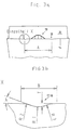
- the front view according to FIG. 3a can be seen that the chip-forming element 19 in the frontal side view shown has flanks sloping to the side, which are at an angle of 35 ° to the cutting edge.
- the upper area, which lies around the vertex, is convex with a constant radius.
- the groove-shaped depressions 17 and 18 are at a distance A which is approximately 44% of the lancing width determined by the length of the straight end cutting edge 14.
- the groove-shaped recess 17 is shown as detail X in Fig. 3b.
- the relevant depression 17 (as well as the depression 18) has a width B which is in the range between 0.05 mm and 1.3 mm, preferably 0.1 mm to 1.0 mm.
- the depth T of the groove is 0.01 mm to 0.4 mm, preferably 0.025 mm to 0.2 mm.
- the side flanks form an angle ⁇ with the rake face 13 or the face cutting edge 14 surrounding them, which is 20 ° in the present case.
- the groove-shaped depressions which have a constant width and a constant shape over their length down to the outlet zone, have a radius R 1 between 0.08 mm and 1.0 mm in the groove base and respective convex edge regions with larger radii of curvature R 2 and R 3 , which are preferably between 0.2 mm and 0.7 mm.
- the raised chip-forming element is arranged at a distance from the cutting edge 14 and is surrounded by a rake face area 13 which slopes down to areas far from the face edge, wherein it can have a substantially flat surface or a concave configuration.
- the angle of inclination with respect to a horizontal plane is approx. 4 °.
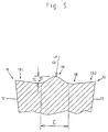
- the cut perpendicular to the longitudinal axis of the groove which lies approximately in the region of the apex of the raised chip-forming element 19, illustrates the height H of the apex mentioned to the chip base surface surrounding it, which lies between 0.05 mm and 1.5 mm.
- the radius of curvature R 4 is of the order of R 1 , R 2 or R 3 .
- the base width C of the chip-forming element 19 is between 0.3 mm to 5 mm.
- the groove-shaped recesses 17 and 18 are located on both sides and mirror-symmetrically to the raised chip-forming element 19.
- the rake edge regions 131 and 132 rise towards the secondary cutting edges 15 and 16, the angle of inclination to the end cutting edge 14 being between -4 ° and + 8 °.
- Fig. 10 shows further cutting profiles of the above Lancing insert, which is circular-arc-shaped (see reference line 22), convex polygonal (see reference line 23) or straight (see Reference line 24) are formed with a smaller puncture width.
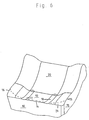
- FIG. 6 An alternative embodiment of the cutting insert is Fig. 6 can be seen. With the cutting insert shown there are the same parts as in the cutting insert described above provided with the same reference numerals, including the groove-shaped ones Wells 17 and 18 in a similar manner break through the cutting edge 14. In terms of their dimensions that applies to the cutting insert according to FIGS. 1 to 5.
- This cutting insert has between the groove-shaped depressions 17 and 18 no chip-forming element.
- the rake face 13 falls after the end cutting edge 14 between groove-shaped Wells 17 and 18 as a hollow with a concave formation from, while the lateral edge areas between the groove-shaped depressions 17 and 18 and the secondary cutting edges 15 and 16 are formed too high and thereby stabilizing Act.
- These rake edge areas are vertical Direction to the cutting edge 14 in contrast to that described Rake face recess running so that it is there form a chamfer 21 before moving to areas far from the face at 0 ° angles or falling angles in front of the rising surface 20 run.
- the chamfer 21 lies in the cutting corner area preferably at a negative rake angle and has a direction the longitudinal insertion axis there is a greater length than in Middle area of the front edge.
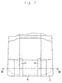
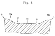
- the sectional view according to Section line VIII - VIII according to FIG. 7 shows the lowered one in FIG. 8 Area 133, which is straight in the sectional view. Form laterally of the trough-shaped depressions 17 and 18 the flanks of the rake edge areas have an angle of approx. 30 ° with the horizontal plane of the central rake face 133. Following the side rising edges follows in the Areas 134 and 135 a convex area to an in Cut straight outflow to minor cutting edge 15 or 16.
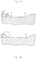
- FIGS. 9a and 9b Possible alternative designs of the relevant rake edge areas 134 and 135 can be seen from FIGS. 9a and 9b, in particular, the respective flank angles ⁇ and ⁇ , the 9a are 45 ° or 30 °, the same, approximately below 35 ° as shown in Fig. 9b.
- the groove-shaped Recesses 17 and 18 facing lateral rake flanks are arranged in the figures shown so that their lower foot area adjacent to the central area with the groove-shaped recesses 17 and d18 are aligned.
- the groove-shaped recesses 17 and 18th to be arranged so that they are closer together (but in compliance with of the defined minimum distance), so that they are in the middle of a linear cross-sectional central area to which the respective falling flanks of the rake face edge regions on both sides adjoin.
Landscapes
- Engineering & Computer Science (AREA)
- Mechanical Engineering (AREA)
- Cutting Tools, Boring Holders, And Turrets (AREA)
- Milling Processes (AREA)
Abstract
Description
- Die Erzeugung eines im wesentlichen ebenen Nutgrundes bei geraden Einstichen,
- eine hohe Oberflächengüte der Nutflanken,
- Wirksamkeit bei unterschiedlichen Schneidenprofilen, insbesondere kreisbogenförmigen und polygonalen Schhneidenprofilen,
- einen kontrollierten Spanbruch in einem breiten Vorschubbereich einschließlich kleinster Vorschübe / Spanungsdicken,
- einen kontrollieren Spanbruch bei duktilen Werkstückstoffen und
- keine Einbußen in der Schneidenstabilität.
- Fig. 1
- eine perspektivische Ansicht eines erfindungsgemäßen Stecheinsatzes mit nutenförmigen Vertiefungen und einem dazwischen angeordneten erhabenen Spanformelement,
- Fig. 2
- eine Draufsicht auf den Stecheinsatz nach Fig. 1 auf einen Teilbereich der sich an die Stirnschneide anschließenden Schneidkanten,
- Fig. 3a
- eine Vorderansicht des Stecheinsatzes nach Fig. 1 oder 2,
- Fig. 3b
- eine Ausschnittvergrößerung der Einzelheit X nach Fig. 3a,
- Fig. 4
- einen Längsschnitt gemäß Linie IV - IV in Fig. 2,
- Fig. 5
- einen Querschnitt gemäß Linie V - V in Fig. 2,
- Fig. 6
- eine alternative Ausgestaltung des Stecheinsatzes in perspektivischer Darstellung, in einer Teilansicht,
- Fig. 7
- eine Draufsicht auf den Stecheinsatz nach Fig. 6,
- Fig. 8
- einen Querschnitt entlang Linie VIII - VIII in Fig. 7,
- Fig. 9a, b
- alternativ mögliche Querschnitte zu der Ausführungsform nach Fig. 8.
- Fig. 10
- eine perspektivische Ansicht des Schneideinsatzes gemäß Fig. 1, bei dem mögliche konvexe polygonale oder kreisbogenförmige Ausgestaltungen angedeutet sind.
Claims (10)
- Stecheinsatz zur spanabhebenden Bearbeitung von Werkstücken, mit mindestens einer vorderen Schneidkante (Stirnschneide) (14), die von zwei achsensymmetrisch und parallel zur Stecheinsatzlängsachse in der Spanfläche (13) liegenden nutenförmigen Vertiefungen (17, 18) mit über ihre Länge (L) gleichbleibender Breite (B) durchbrochen wird, die einen lateralen Abstand (A) zwischen 30 % und 80 %, vorzugsweise 40 % bis 65 %, der Stechbreite und - bezogen auf die die nutenförmigen Vertiefungen (17, 18) umgebende Spanfläche (13) - eine Nuttiefe (T) zwischen 0,01 mm und 0,4 mm aufweisen.
- Stecheinsatz nach Anspruch 1, dadurch gekennzeichnet, daß die Länge (L) der nutförmigen Vertiefungen (17, 18) zwischen 1,0 mm und 10 mm liegt und/oder mindestens das 1,2-fache der Nutenbreite (B) beträgt, die im Bereich zwischen 0,05 mm und 1,3 mm, vorzugsweise zwischen 0,1 mm und 1,0 mm, oder zwischen 3 % bis 20 %, vorzugsweise 5 % bis 15 % der Stechbreite beträgt.
- Stecheinsatz nach Anspruch 1 oder 2, dadurch gekennzeichnet, daß die nutenförmigen Vertiefungen (17, 18) in einem Querschnitt senkrecht zu ihrer Längsachse einen mittleren konkaven Nutgrundbereich mit einem Krümmungsradius (R1) zwischen 0,08 mm und 1,0 mm, vorzugsweise 0,15 mm bis 00,4 mm, und jeweilige konvexe Randbereiche mit größeren Krümmungsradien (R2, R3) vorzugsweise zwischen 0,1 mm bis 1,5 mm, weiterhin vorzugsweise zwischen 0,2 mm und 0,7 mm aufweisen.
- Stecheinsatz nach einem der Ansprüche 1 bis 3, dadurch gekennzeichnet, daß das Breite-Tiefe-Verhältnis (B/T) der nutenförmigen Vertiefungen (17, 18) zwischen 3 und 30, vorzugsweise 8 und 15 liegt.
- Stecheinsatz nach einem der Ansprüche 1 bis 4, dadurch gekennzeichnet, daß zwischen den und/oder beidseitig der nutförmigen Vertiefungen (17, 18) ein sich zum Scheitelpunkt verjüngendes erhabenes Spanformelement (19) bzw. jeweils Spanformelemente angeordnet ist/sind, wobei weiterhin vorzugsweise das/die erhabene(n) Spanformelement(e) (19) kantenfrei ausgebildet ist/sind und/oder auf der der Stirnschneide (14) zugewandten Seite eine Anstiegsfläche mit einem Anstiegswinkel (ϕ) zwischen 10° und 45°, vorzugsweise zwischen 12° und 30°, aufweist/aufweisen und/oder die Anstiegsfläche keilförmig ausgebildet ist.
- Stecheinsatz nach Anspruch 5, dadurch gekennzeichnet, daß das oder die Spanformelement(e) (19) eine gegenüber der sie umgebenden Spanbasisfläche (13) gemessene Höhe (H) zwischen 0,05 mm und 1,5 mm, vorzugsweise 0,1 mm bis 0,8 mm, und/oder eine Basisbreite (C) zwischen 0,3 mm bis 5 mm, vorzugsweise zwischen 0,7 mm und 3 mm, oder zwischen 20 % bis 70 %, vorzugsweise 25 % bis 45 %, der Stechbreite aufweist/aufweisen.
- Stecheinsatz nach einem der Ansprüche 5 oder 6, dadurch gekennzeichnet, daß das Spanformelement (19) im Querschnitt senkrecht zur Stecheinsatzlängsachse im Bereich um den Scheitelpunkt eine konvexe Krümmung aufweist, deren Radius (R4) vorzugsweise etwa gleich der radialen Krümmung der nutenförmigen Vertiefungen (17, 18) ist.
- Stecheinsatz nach einem der Ansprüche 1 bis 7, dadurch gekennzeichnet, daß die Spanbasisfläche (13) ausgehend von der Stirnschneide (14) und/oder den Nebenschneiden (15, 16) oder von einer hier angrenzenden Fase unter einem senkrecht zur Schneidkante gemessenen Spanwinkel ≤10°, vorzugsweise ≤8°, einlauft.
- Stecheinsatz nach einem der Ansprüche 1 bis 8, dadurch gekennzeichnet, daß die Spanfläche (13) zwischen den nutförmigen Vertiefungen (17, 18) als abgesenkter Mittelbereich (133) ausgebildet ist und/oder sich zwischen den nutförmigen Vertiefungen (17, 18) und den Nebenschneiden (15, 16) erhöhte Spanflächenrandbereiche (131, 132, 134, 135) erstrecken, wobei vorzugsweise die quer zur Stecheinsatzlängsachse liegenden Anstiegsflanken der erhöhten Spanflächenrandbereiche im wesentlichen konvex ausgebildet sind und die nutenförmigen Vertiefungen (17, 18) mit den Grenzen zwischen dem abgesenkten Mittelbereich (133) und den erhöhten Spanflächenrandbereichen im wesentlichen fluchten.
- Stecheinsatz nach einem der Ansprüche 1 bis 9, dadurch gekennzeichnet, daß die Schneide quer zur Stecheinsatzlängsachse angeordnet und gerade ist oder kreisbogenförmig oder konvex polygonal ausgebildet ist.
Applications Claiming Priority (3)
| Application Number | Priority Date | Filing Date | Title |
|---|---|---|---|
| DE19527696 | 1995-07-28 | ||
| DE19527696A DE19527696A1 (de) | 1995-07-28 | 1995-07-28 | Stecheinsatz |
| PCT/DE1996/001389 WO1997004907A1 (de) | 1995-07-28 | 1996-07-22 | Stecheinsatz |
Publications (2)
| Publication Number | Publication Date |
|---|---|
| EP0842003A1 EP0842003A1 (de) | 1998-05-20 |
| EP0842003B1 true EP0842003B1 (de) | 1999-10-06 |
Family
ID=7768072
Family Applications (1)
| Application Number | Title | Priority Date | Filing Date |
|---|---|---|---|
| EP96928332A Expired - Lifetime EP0842003B1 (de) | 1995-07-28 | 1996-07-22 | Stecheinsatz |
Country Status (4)
| Country | Link |
|---|---|
| EP (1) | EP0842003B1 (de) |
| JP (1) | JPH11509784A (de) |
| DE (2) | DE19527696A1 (de) |
| WO (1) | WO1997004907A1 (de) |
Families Citing this family (7)
| Publication number | Priority date | Publication date | Assignee | Title |
|---|---|---|---|---|
| DE19739855A1 (de) * | 1997-09-11 | 1999-04-15 | Afos Geraete Herstellungs Und | Spanabhebendes Werkzeug mit Schneideinsatz |
| US6196910B1 (en) | 1998-08-10 | 2001-03-06 | General Electric Company | Polycrystalline diamond compact cutter with improved cutting by preventing chip build up |
| DE10042692A1 (de) * | 2000-08-31 | 2002-03-28 | Horn P Hartmetall Werkzeugfab | Vorrichtung zum spanenden Bearbeiten von Werkstücken, insbesondere Metallschneideeinsatz mit einer zwischen Stegen angeordneten Spanformfläche |
| KR20080099471A (ko) * | 2007-05-09 | 2008-11-13 | 대구텍 주식회사 | 분단 및 모깍기 용 인서트 |
| AT13995U1 (de) * | 2013-05-27 | 2015-02-15 | Ceratizit Austria Gmbh | Schneideinsatz aus Hartmetall oder Cermet für die Drehbearbeitung |
| JP6162544B2 (ja) * | 2013-08-27 | 2017-07-12 | 京セラ株式会社 | スローアウェイチップ、スローアウェイ式切削工具および切削加工物の製造方法 |
| CN106132601B (zh) * | 2014-03-25 | 2018-12-11 | 京瓷株式会社 | 切削镶刀、切削工具以及切削加工物的制造方法 |
Family Cites Families (10)
| Publication number | Priority date | Publication date | Assignee | Title |
|---|---|---|---|---|
| DE2404302C2 (de) * | 1974-01-30 | 1986-04-17 | Zinner, Karl, 8500 Nürnberg | Schneidmeißel für ein Abstechwerkzeug |
| IL62278A (en) * | 1981-03-03 | 1984-10-31 | Iscar Ltd | Rotational cutting tool |
| DE88426T1 (de) * | 1982-03-10 | 1984-02-16 | Kennametal Inc., 15650 Latrobe, Pa. | Schneidwerkzeug-montierung. |
| FR2561960B1 (fr) * | 1984-03-30 | 1988-01-15 | Danit Carbex Sa | Plaquette de coupe |
| DE3819415A1 (de) * | 1988-06-07 | 1989-12-14 | Karl Heinz Arnold Gmbh | Schneidplatte zum stechdrehen |
| DE3907922A1 (de) * | 1989-03-11 | 1990-04-26 | Zinner Gmbh Praezisionswerkzeu | Spanendes werkzeug |
| SU1720802A1 (ru) * | 1990-03-11 | 1992-03-23 | Научно-Исследовательская Лаборатория "Карбидные Материалы" | Резец |
| IL97746A (en) * | 1991-04-02 | 1995-01-24 | Iscar Ltd | Metal cutting tool |
| SE508121C2 (sv) * | 1992-04-30 | 1998-08-31 | Sandvik Ab | Skär för svarvnings- och spårstickningsverktyg |
| DE4310131A1 (de) * | 1993-03-29 | 1994-10-06 | Krupp Widia Gmbh | Schneideinsatz |
-
1995
- 1995-07-28 DE DE19527696A patent/DE19527696A1/de not_active Withdrawn
-
1996
- 1996-07-22 WO PCT/DE1996/001389 patent/WO1997004907A1/de not_active Ceased
- 1996-07-22 JP JP9507098A patent/JPH11509784A/ja not_active Ceased
- 1996-07-22 DE DE59603293T patent/DE59603293D1/de not_active Expired - Lifetime
- 1996-07-22 EP EP96928332A patent/EP0842003B1/de not_active Expired - Lifetime
Also Published As
| Publication number | Publication date |
|---|---|
| DE19527696A1 (de) | 1997-01-30 |
| EP0842003A1 (de) | 1998-05-20 |
| WO1997004907A1 (de) | 1997-02-13 |
| JPH11509784A (ja) | 1999-08-31 |
| DE59603293D1 (de) | 1999-11-11 |
Similar Documents
| Publication | Publication Date | Title |
|---|---|---|
| EP0674557B1 (de) | Schneideinsatz | |
| EP0674559B1 (de) | Schneideinsatz | |
| EP0617647B1 (de) | Schneideinsatz mit entlang der schneidkante sich erstreckenden trapezförmigen eindrückungen | |
| EP0587592B1 (de) | Vieleckiger oder runder schneideinsatz | |
| EP0787049B1 (de) | Vieleckiger schneideinsatz | |
| DE68907004T2 (de) | Schneideinsatz. | |
| DE3841320A1 (de) | Schneideinsatz mit erhoehter schneidkante | |
| WO1995029782A1 (de) | Werkzeug für die spanende bearbeitung | |
| EP2106344B1 (de) | Schneideinsatz | |
| EP0073926A1 (de) | Schneidwerkzeug, insbesondere Wendeschneidplatte | |
| EP0781181B1 (de) | Stecheinsatz zur spanabhebenden bearbeitung von werkstücken | |
| DE4422312A1 (de) | Schneideinsatz | |
| DE60019438T2 (de) | Schneideinsatz zum einstecken | |
| EP0842003B1 (de) | Stecheinsatz | |
| EP0706432B1 (de) | Schneideinsatz | |
| DE4310131A1 (de) | Schneideinsatz | |
| WO1994027768A1 (de) | Schneideinsatz | |
| EP0758281B1 (de) | Schneideinsatz, insbesondere zum fräsen | |
| EP3898045A1 (de) | Schneidwerkzeug | |
| DE19725341B4 (de) | Schneidwerkzeug für schälartige Zerspanungsbearbeitungen | |
| DE202018107335U1 (de) | Schneidwerkzeug | |
| DE29807877U1 (de) | Messerplatte | |
| EP0955116A1 (de) | Messerplatte | |
| EP4570402A1 (de) | Abstechwerkzeug | |
| DE29509664U1 (de) | Stecheinsatz |
Legal Events
| Date | Code | Title | Description |
|---|---|---|---|
| PUAI | Public reference made under article 153(3) epc to a published international application that has entered the european phase |
Free format text: ORIGINAL CODE: 0009012 |
|
| 17P | Request for examination filed |
Effective date: 19971220 |
|
| AK | Designated contracting states |
Kind code of ref document: A1 Designated state(s): DE FR GB IT |
|
| GRAG | Despatch of communication of intention to grant |
Free format text: ORIGINAL CODE: EPIDOS AGRA |
|
| 17Q | First examination report despatched |
Effective date: 19981218 |
|
| GRAG | Despatch of communication of intention to grant |
Free format text: ORIGINAL CODE: EPIDOS AGRA |
|
| GRAH | Despatch of communication of intention to grant a patent |
Free format text: ORIGINAL CODE: EPIDOS IGRA |
|
| GRAH | Despatch of communication of intention to grant a patent |
Free format text: ORIGINAL CODE: EPIDOS IGRA |
|
| GRAA | (expected) grant |
Free format text: ORIGINAL CODE: 0009210 |
|
| AK | Designated contracting states |
Kind code of ref document: B1 Designated state(s): DE FR GB IT |
|
| GBT | Gb: translation of ep patent filed (gb section 77(6)(a)/1977) |
Effective date: 19991006 |
|
| ET | Fr: translation filed | ||
| REF | Corresponds to: |
Ref document number: 59603293 Country of ref document: DE Date of ref document: 19991111 |
|
| ITF | It: translation for a ep patent filed | ||
| PLBE | No opposition filed within time limit |
Free format text: ORIGINAL CODE: 0009261 |
|
| STAA | Information on the status of an ep patent application or granted ep patent |
Free format text: STATUS: NO OPPOSITION FILED WITHIN TIME LIMIT |
|
| 26N | No opposition filed | ||
| REG | Reference to a national code |
Ref country code: GB Ref legal event code: IF02 |
|
| PGFP | Annual fee paid to national office [announced via postgrant information from national office to epo] |
Ref country code: GB Payment date: 20030626 Year of fee payment: 8 |
|
| PGFP | Annual fee paid to national office [announced via postgrant information from national office to epo] |
Ref country code: FR Payment date: 20030724 Year of fee payment: 8 |
|
| PG25 | Lapsed in a contracting state [announced via postgrant information from national office to epo] |
Ref country code: GB Free format text: LAPSE BECAUSE OF NON-PAYMENT OF DUE FEES Effective date: 20040722 |
|
| GBPC | Gb: european patent ceased through non-payment of renewal fee |
Effective date: 20040722 |
|
| PG25 | Lapsed in a contracting state [announced via postgrant information from national office to epo] |
Ref country code: FR Free format text: LAPSE BECAUSE OF NON-PAYMENT OF DUE FEES Effective date: 20050331 |
|
| REG | Reference to a national code |
Ref country code: FR Ref legal event code: ST |
|
| PG25 | Lapsed in a contracting state [announced via postgrant information from national office to epo] |
Ref country code: IT Free format text: LAPSE BECAUSE OF NON-PAYMENT OF DUE FEES;WARNING: LAPSES OF ITALIAN PATENTS WITH EFFECTIVE DATE BEFORE 2007 MAY HAVE OCCURRED AT ANY TIME BEFORE 2007. THE CORRECT EFFECTIVE DATE MAY BE DIFFERENT FROM THE ONE RECORDED. Effective date: 20050722 |
|
| PGFP | Annual fee paid to national office [announced via postgrant information from national office to epo] |
Ref country code: DE Payment date: 20100927 Year of fee payment: 15 |
|
| PG25 | Lapsed in a contracting state [announced via postgrant information from national office to epo] |
Ref country code: DE Free format text: LAPSE BECAUSE OF NON-PAYMENT OF DUE FEES Effective date: 20120201 |
|
| REG | Reference to a national code |
Ref country code: DE Ref legal event code: R119 Ref document number: 59603293 Country of ref document: DE Effective date: 20120201 |