EP0842003B1 - Recessing tool insert - Google Patents
Recessing tool insert Download PDFInfo
- Publication number
- EP0842003B1 EP0842003B1 EP96928332A EP96928332A EP0842003B1 EP 0842003 B1 EP0842003 B1 EP 0842003B1 EP 96928332 A EP96928332 A EP 96928332A EP 96928332 A EP96928332 A EP 96928332A EP 0842003 B1 EP0842003 B1 EP 0842003B1
- Authority
- EP
- European Patent Office
- Prior art keywords
- groove
- recessing
- tool insert
- cutting
- chip
- Prior art date
- Legal status (The legal status is an assumption and is not a legal conclusion. Google has not performed a legal analysis and makes no representation as to the accuracy of the status listed.)
- Expired - Lifetime
Links
- 238000003754 machining Methods 0.000 claims abstract description 3
- 230000009194 climbing Effects 0.000 claims 3
- 238000007493 shaping process Methods 0.000 claims 3
- 230000000630 rising effect Effects 0.000 description 7
- 230000015572 biosynthetic process Effects 0.000 description 3
- 210000001061 forehead Anatomy 0.000 description 3
- 230000006641 stabilisation Effects 0.000 description 3
- 238000011105 stabilization Methods 0.000 description 3
- 230000000087 stabilizing effect Effects 0.000 description 3
- 230000001174 ascending effect Effects 0.000 description 2
- 230000000694 effects Effects 0.000 description 2
- 239000000463 material Substances 0.000 description 2
- 230000003313 weakening effect Effects 0.000 description 2
- 241000219504 Caryophyllales Species 0.000 description 1
- 239000011324 bead Substances 0.000 description 1
- 238000011161 development Methods 0.000 description 1
- 230000018109 developmental process Effects 0.000 description 1
- 238000003780 insertion Methods 0.000 description 1
- 230000037431 insertion Effects 0.000 description 1
- 238000000465 moulding Methods 0.000 description 1
- 238000005457 optimization Methods 0.000 description 1
- 230000007704 transition Effects 0.000 description 1
- 238000011144 upstream manufacturing Methods 0.000 description 1
Images


Classifications
-
- B—PERFORMING OPERATIONS; TRANSPORTING
- B23—MACHINE TOOLS; METAL-WORKING NOT OTHERWISE PROVIDED FOR
- B23B—TURNING; BORING
- B23B27/00—Tools for turning or boring machines; Tools of a similar kind in general; Accessories therefor
- B23B27/04—Cutting-off tools
- B23B27/045—Cutting-off tools with chip-breaking arrangements
-
- B—PERFORMING OPERATIONS; TRANSPORTING
- B23—MACHINE TOOLS; METAL-WORKING NOT OTHERWISE PROVIDED FOR
- B23B—TURNING; BORING
- B23B2200/00—Details of cutting inserts
- B23B2200/32—Chip breaking or chip evacuation
- B23B2200/321—Chip breaking or chip evacuation by chip breaking projections
-
- B—PERFORMING OPERATIONS; TRANSPORTING
- B23—MACHINE TOOLS; METAL-WORKING NOT OTHERWISE PROVIDED FOR
- B23B—TURNING; BORING
- B23B2200/00—Details of cutting inserts
- B23B2200/32—Chip breaking or chip evacuation
- B23B2200/323—Chip breaking or chip evacuation by chip breaking depressions
Definitions
- the invention relates to a lancing insert for cutting Machining workpieces with at least one front, preferably arranged transversely to the longitudinal axis of the lancing insert Cutting edge (end cutting edge).
- a lancing insert is e.g. known from EP-A-0 568 512.
- the lancing insert according to DE 38 19 415 C2 has in the Forehead edge adjacent rake face a recess in the front from one of the forehead edge forming a positive one Rake angle declining and coming from that of the cutting edges main plane sloping surface extending backwards downward is limited as well as one by the main cutting edge outgoing support surface on which the from the main cutting edge coming and down next to the support surface into the depression molding chips.
- the middle depression is to each of the two cutting edges from one of the relevant cutting edge with formation of a positive rake angle sloping minor cutting edge bevel.
- the Support surface is one between the minor cutting bevels arranged, the recess in the longitudinal direction of the insert continuous longitudinal rib arrangement formed, the two each facing a minor cutting edge and for that of the associated cutting edge coming chips one after the chips has deflecting top deflecting side surfaces.
- the raised longitudinal ribs with support surfaces are the start from the forehead edge, neither for a sufficient Chip control still a desired chip narrowing suitable.
- DE 39 07 922 C2 describes a lancing insert with a Rake face that has a central area with at least one convex Calotte and at least one the central area on all sides surrounding and sloping edge section opposite him having.
- the front edge section that of the calotte mentioned upstream in the central area, there should be at least one more concave or convex dome and one or more between groove-like depressions arranged at the edge sections be provided that connect the central area with the edges.
- the chip form elements mentioned work in practice not together as desired, so that no sufficient narrowing the span is attainable. They also weaken groove-like depressions running into the cutting corners Cutting corners. Knobs directly adjacent to the front edge can only be used in a narrowly limited feed range and harbor the risk of chip build-up on larger feeds.
- the lancing width results from the maximum distance of the Cutting points perpendicular to the longitudinal axis of the lancing insert.
- the chip cross-section beads which increases the section modulus and the emergence long spiral or tangled chips is largely prevented.
- the Bead-shaped chip cross-sectional shape at a sufficient distance from The chip edges create defined folds around the the edges of the chip under the influence of the raised Minor edge of adjacent edge areas are bent up, so that the chip width is reduced compared to the groove width and the chip can escape from the groove without interference. This leads to a good surface of the groove flanks. Furthermore are the groove-shaped depressions far away from the minor cutting edges, so that a weakening of the cutting corners is avoided.
- the groove-shaped depressions are essentially in the direction of chip flow and serve the chip formation stabilization.
- the lancing insert can be single-edged or also multi-edged, with on opposite Be arranged side cutting edges.
- the length of the groove-shaped depressions is preferably between 1.0 mm and 10 mm and / or at least that 1.2 times the groove width, which ranges between 0.05 mm and 1.3 mm, preferably between 0.1 mm and 1.0 mm, or between 3% to 20%, preferably 5% to 15%, of the lancing width is chosen.
- the aforementioned length of the depressions is coordinated to the area where the plastic deformations of the expiring chip can be generated effectively.
- the groove width is preferably chosen within the specified limits on the one hand, a sufficiently large effect of the groove-shaped depressions guarantee and on the other hand a weakening as well as to avoid excessive profile distortion of the cutting edge.
- the groove-shaped depressions have a cross section a central concave perpendicular to its longitudinal axis Groove base area with a radius of curvature between 0.08 mm and 1.0 mm, preferably 0.15 mm to 0.4 mm, and respective convex Edge areas with larger radii of curvature. These lie according to a further embodiment of the invention between 0.1 mm up to 1.5 mm, preferably between 0.2 mm and 0.7 mm.
- An optimized one Bead-shaped chip cross-sectional shape results when the groove-shaped depressions in a cross section perpendicular considered a tangential flank inclination angle to its longitudinal axis have between 12 ° and 50 °, preferably 15 ° and 30 °.
- a further optimization can be done by choosing the width-depth ratio the groove-shaped depressions between 3 and 30, preferably 8 to 15, can be achieved.
- the rising surface can also be wedge-shaped to ensure low-friction chip flow to ensure.
- the chip shape or elements have a compared to the height measured around the chip base area between 0.05 mm and 1.5 mm, preferably between 0.1 mm to 0.8 mm.
- their base width is 0.3 mm to 5 mm, preferably 0.7 mm to 3 mm, or them is between 20% to 70%, preferably 25% to 45%, of lancing width defined by the length of a cutting edge.
- the front base is at the base of the Spanformes arranged at a distance from the cutting edge.
- the base width is 0.4 mm to 4 mm, preferably at a distance of the wells between 0.5 mm and 5 mm.
- the Lancing insert on the front edge outside the groove-shaped Wells and / or stabilizing chamfers adjacent to the minor cutting edges has preferred widths between 0.03 mm and 0.4 mm, while the width of the adjacent cutting edge Stabilizing chamfers between 0.1 mm and 2 mm selected becomes.
- the lateral stabilization chamfers adjoining the minor cutting edge can opposite the central chip drainage surface be increased, the contour of which follows the Face cutting edge and is convex perpendicular to it.
- the chip base surface preferably runs from the end cutting edge and / or the minor cutting edges or from one here adjacent chamfer under a measured perpendicular to the cutting edge Rake angle ⁇ 10 °, further preferably ⁇ 8 °.
- the rake surface between the groove-shaped Depressions can be formed as a lowered central region. Additionally or alternatively, the can be between the groove-shaped Depressions and the secondary cutting edges extending Rake edge areas are elevated, preferably the Rising flanks of the raised rake edge regions essentially convex be and the groove-shaped depressions with the borders between the lowered central area and the raised rake edge areas essentially aligned.
- the groove-shaped depressions lie on the border line, which without these groove-shaped depressions to the middle Rake area would result.
- the groove-shaped depressions to the boundary lines defined above between the middle area and the rising flanks have a lateral distance that is less than 15% of the through the face edge length is the specified cutting width.
- the through the set rake angle of the lancing insert and the feed essentially determined chip thickness should be so be chosen that the width and / or the depth of the groove-shaped Wells is 15% to 100% of this chip thickness.
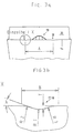
- the lancing insert has a front open area 10, each Secondary free surfaces 11, 12, which together with the rake surface 13 a front cutting edge 14 and secondary cutting edges 15 and 16 form.
- a front cutting edge 14 and secondary cutting edges 15 and 16 At a distance from each other and at a distance from the secondary cutting edges 15 and 16 are groove-shaped in the rake face 13 Recesses 17 and 18, which the front cutting edge 14th break through and a constant width along the length (with the exception of the rear outlet zone).
- Center to the groove-shaped depressions 17 and 18 is a raised one Spanformelement 19 arranged, the design of which by Profile lines becomes clear.
- the rake face of the cutting insert can be from the cutting edge starting from a positive rake face angle. As well positive clearance angles as well as 0 ° clearance angles are possible.
- the lancing insert has areas far from the cutting edge Rising surface 20, which is used to bend the chip perpendicular to the chip flow plane serves. This rising surface ends in a crest line, which runs approximately parallel to the cutting edge 14 and behind which the adjoining area falls and this descending area Flank can also be used as a stop for a holder in which the lancing insert is inserted.
- the raised chip-forming element 19 runs forward, i.e. wedge-shaped towards the cutting edge 14, whereby the front base point 22 at a distance from the cutting edge 14 is arranged. Broadened to areas far from the cutting edge the chip form element up to a maximum width, approximately in Height of the section V - V, on the line of which also the upper one The vertex of the edge-free chip form element lies.
- the raised chip form element falls off more steeply, whereby the approximate drop shape shown in Fig. 2 results.
- the raised chip form element is longer than wide, with the rear boundary line of the chip form element to the rake face 13 in front of the outlet areas of the groove-shaped Wells 17 and 18 is the middle chip forming element 19 to the rear by about half the length of the chip-forming element tower over.
- the front one through to the cutting edge 14 formed by the base line of the chip forming element 19 Wedge angle is 70 ° to 90 °, preferably 75 ° to 85 °.
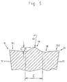
- the front view according to FIG. 3a can be seen that the chip-forming element 19 in the frontal side view shown has flanks sloping to the side, which are at an angle of 35 ° to the cutting edge.
- the upper area, which lies around the vertex, is convex with a constant radius.
- the groove-shaped depressions 17 and 18 are at a distance A which is approximately 44% of the lancing width determined by the length of the straight end cutting edge 14.
- the groove-shaped recess 17 is shown as detail X in Fig. 3b.
- the relevant depression 17 (as well as the depression 18) has a width B which is in the range between 0.05 mm and 1.3 mm, preferably 0.1 mm to 1.0 mm.
- the depth T of the groove is 0.01 mm to 0.4 mm, preferably 0.025 mm to 0.2 mm.
- the side flanks form an angle ⁇ with the rake face 13 or the face cutting edge 14 surrounding them, which is 20 ° in the present case.
- the groove-shaped depressions which have a constant width and a constant shape over their length down to the outlet zone, have a radius R 1 between 0.08 mm and 1.0 mm in the groove base and respective convex edge regions with larger radii of curvature R 2 and R 3 , which are preferably between 0.2 mm and 0.7 mm.
- the raised chip-forming element is arranged at a distance from the cutting edge 14 and is surrounded by a rake face area 13 which slopes down to areas far from the face edge, wherein it can have a substantially flat surface or a concave configuration.
- the angle of inclination with respect to a horizontal plane is approx. 4 °.
- the cut perpendicular to the longitudinal axis of the groove which lies approximately in the region of the apex of the raised chip-forming element 19, illustrates the height H of the apex mentioned to the chip base surface surrounding it, which lies between 0.05 mm and 1.5 mm.
- the radius of curvature R 4 is of the order of R 1 , R 2 or R 3 .
- the base width C of the chip-forming element 19 is between 0.3 mm to 5 mm.
- the groove-shaped recesses 17 and 18 are located on both sides and mirror-symmetrically to the raised chip-forming element 19.
- the rake edge regions 131 and 132 rise towards the secondary cutting edges 15 and 16, the angle of inclination to the end cutting edge 14 being between -4 ° and + 8 °.
- Fig. 10 shows further cutting profiles of the above Lancing insert, which is circular-arc-shaped (see reference line 22), convex polygonal (see reference line 23) or straight (see Reference line 24) are formed with a smaller puncture width.
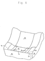
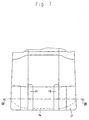
- FIG. 6 An alternative embodiment of the cutting insert is Fig. 6 can be seen. With the cutting insert shown there are the same parts as in the cutting insert described above provided with the same reference numerals, including the groove-shaped ones Wells 17 and 18 in a similar manner break through the cutting edge 14. In terms of their dimensions that applies to the cutting insert according to FIGS. 1 to 5.
- This cutting insert has between the groove-shaped depressions 17 and 18 no chip-forming element.
- the rake face 13 falls after the end cutting edge 14 between groove-shaped Wells 17 and 18 as a hollow with a concave formation from, while the lateral edge areas between the groove-shaped depressions 17 and 18 and the secondary cutting edges 15 and 16 are formed too high and thereby stabilizing Act.
- These rake edge areas are vertical Direction to the cutting edge 14 in contrast to that described Rake face recess running so that it is there form a chamfer 21 before moving to areas far from the face at 0 ° angles or falling angles in front of the rising surface 20 run.
- the chamfer 21 lies in the cutting corner area preferably at a negative rake angle and has a direction the longitudinal insertion axis there is a greater length than in Middle area of the front edge.
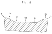
- the sectional view according to Section line VIII - VIII according to FIG. 7 shows the lowered one in FIG. 8 Area 133, which is straight in the sectional view. Form laterally of the trough-shaped depressions 17 and 18 the flanks of the rake edge areas have an angle of approx. 30 ° with the horizontal plane of the central rake face 133. Following the side rising edges follows in the Areas 134 and 135 a convex area to an in Cut straight outflow to minor cutting edge 15 or 16.
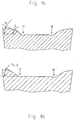
- FIGS. 9a and 9b Possible alternative designs of the relevant rake edge areas 134 and 135 can be seen from FIGS. 9a and 9b, in particular, the respective flank angles ⁇ and ⁇ , the 9a are 45 ° or 30 °, the same, approximately below 35 ° as shown in Fig. 9b.
- the groove-shaped Recesses 17 and 18 facing lateral rake flanks are arranged in the figures shown so that their lower foot area adjacent to the central area with the groove-shaped recesses 17 and d18 are aligned.
- the groove-shaped recesses 17 and 18th to be arranged so that they are closer together (but in compliance with of the defined minimum distance), so that they are in the middle of a linear cross-sectional central area to which the respective falling flanks of the rake face edge regions on both sides adjoin.
Landscapes
- Engineering & Computer Science (AREA)
- Mechanical Engineering (AREA)
- Cutting Tools, Boring Holders, And Turrets (AREA)
- Milling Processes (AREA)
Abstract
Description
Die Erfindung betrifft einen Stecheinsatz zur spanabhebenden Bearbeitung von Werkstücken, mit mindestens einer vorderen, vorzugsweise quer zur Stecheinsatzlängsachse angeordneten Schneidkante (Stirnschneide). Ein derartiger Stecheinsatz ist z.B. aus EP-A-0 568 512 bekannt.The invention relates to a lancing insert for cutting Machining workpieces with at least one front, preferably arranged transversely to the longitudinal axis of the lancing insert Cutting edge (end cutting edge). Such a lancing insert is e.g. known from EP-A-0 568 512.
Um auch bei tiefen Einstichnuten ein einfaches Auslaufen des
Spanes unter Zerbrechung in einzelne Teilstücke zu gewährleisten,
wird in der DE 24 04 302 C2 vorgeschlagen, in der die
Spanleitfläche bildenden Schneidfläche eine langgestreckte, von
der stirnseitigen Freifläche ausgehende Längsnut einzuschleifen,
die sich nur über einen Teil der Länge der Schneidfläche
erstreckt und an ihrem hinteren Ende stoßfrei wieder in die
Schneidfläche einmündet. Die Schneidfläche und der Boden der
Längsnut können unterschiedliche Spanwinkel aufweisen. Erfahrungen
haben gezeigt, daß durch einen solchen Schneideinsatz
keine ausreichende Spankontrolle bei kleinen Vorschüben gewährleistet
werden kann. Entsprechendes gilt für einen Schneideinsatz
nach der EP 0 257 002 A2.In order to ensure that the
To ensure the chip is broken into individual pieces,
is proposed in
Der Stecheinsatz nach DE 38 19 415 C2 besitzt in der an die Stirnschneide angrenzenden Spanfläche eine Vertiefung, die vorn von einer von der Stirnschneide unter Bildung eines positiven Spanwinkels abfallenden und sich dabei aus der von den Schneiden aufgespannten Ebene nach hinten unten erstreckenden Hauptschneiden-Schrägfläche begrenzt ist sowie eine von der Hauptschneide ausgehende Stützfläche, auf der die von der Hauptschneide kommenden und sich neben der Stützfläche in die Vertiefung einformenden Späne aufliegen. Die mittlere Vertiefung wird zu beiden Nebenschneiden hin jeweils von einer von der betreffenden Nebenschneide unter Bildung eines positiven Spanwinkels abfallenden Nebenschneiden-Schrägfläche begrenzt. Die Stützfläche wird von einer zwischen den Nebenschneiden-Schragflächen angeordneten, die Vertiefung in Schneidplattenlängsrichtung durchziehenden Längsrippenanordnung gebildet, die zwei jeweils einer Nebenschneide zugewandte und für die von der zugeordneten Nebenschneide kommende Späne eine die Späne nach oben ablenkende Auflauffläche bildende Seitenflächen aufweist. Allerdings sind die erhabenen Längsrippen mit Stützflächen, die von der Stirnschneide ausgehen, weder für eine ausreichende Spankontrolle noch eine erwünschte Spanverschmälerung geeignet.The lancing insert according to DE 38 19 415 C2 has in the Forehead edge adjacent rake face a recess in the front from one of the forehead edge forming a positive one Rake angle declining and coming from that of the cutting edges main plane sloping surface extending backwards downward is limited as well as one by the main cutting edge outgoing support surface on which the from the main cutting edge coming and down next to the support surface into the depression molding chips. The middle depression is to each of the two cutting edges from one of the relevant cutting edge with formation of a positive rake angle sloping minor cutting edge bevel. The Support surface is one between the minor cutting bevels arranged, the recess in the longitudinal direction of the insert continuous longitudinal rib arrangement formed, the two each facing a minor cutting edge and for that of the associated cutting edge coming chips one after the chips has deflecting top deflecting side surfaces. However, the raised longitudinal ribs with support surfaces are the start from the forehead edge, neither for a sufficient Chip control still a desired chip narrowing suitable.
Die DE 39 07 922 C2 beschreibt einen Stecheinsatz mit einer Spanfläche, die einen Zentralbereich mit wenigstens einer konvexen Kalotte und mindestens einen den Zentralbereich allseits umgebenden und ihm gegenüber schräg ansteigenden Randabschnitt aufweist. Im vorderen Randabschnitt, der der genannten Kalotte im Zentralbereich vorgeschaltet ist, soll wenigstens eine weitere konkave oder konvexe Kalotte und eine oder mehrere zwischen den Randabschnitten angeordnete, nutenartige Vertiefungen vorgesehen sein, die den Zentralbereich mit den Kanten verbinden. Die genannten Spanformelemente wirken in der Praxis jedoch nicht wie gewünscht zusammen, so daß keine ausreichende Verschmälerung der Spanbreite erreichbar ist. Zudem schwächen die in die Schneidecken laufenden nutartigen Vertiefungen die Schneidecken. Unmittelbar an die Stirnschneide angrenzende Noppen sind nur in einem eng begrenzten Vorschubbereich anwendbar und bergen bei größeren Vorschüben die Gefahr eines Spänestaues.DE 39 07 922 C2 describes a lancing insert with a Rake face that has a central area with at least one convex Calotte and at least one the central area on all sides surrounding and sloping edge section opposite him having. In the front edge section, that of the calotte mentioned upstream in the central area, there should be at least one more concave or convex dome and one or more between groove-like depressions arranged at the edge sections be provided that connect the central area with the edges. However, the chip form elements mentioned work in practice not together as desired, so that no sufficient narrowing the span is attainable. They also weaken groove-like depressions running into the cutting corners Cutting corners. Knobs directly adjacent to the front edge can only be used in a narrowly limited feed range and harbor the risk of chip build-up on larger feeds.
Es ist Aufgabe der vorliegenden Erfindung, einen Schneideinsatz, vor allen Dingen zum Stechdrehen zu schaffen, der mindestens eine der folgenden Forderungen erfüllt:
- Die Erzeugung eines im wesentlichen ebenen Nutgrundes bei geraden Einstichen,
- eine hohe Oberflächengüte der Nutflanken,
- Wirksamkeit bei unterschiedlichen Schneidenprofilen, insbesondere kreisbogenförmigen und polygonalen Schhneidenprofilen,
- einen kontrollierten Spanbruch in einem breiten Vorschubbereich einschließlich kleinster Vorschübe / Spanungsdicken,
- einen kontrollieren Spanbruch bei duktilen Werkstückstoffen und
- keine Einbußen in der Schneidenstabilität.
- The generation of an essentially flat groove base with straight recesses,
- a high surface quality of the groove flanks,
- Effectiveness with different cutting edge profiles, especially circular arc and polygonal cutting edge profiles,
- a controlled chip break in a wide feed range including the smallest feeds / chip thicknesses,
- control chip breakage in ductile workpiece materials and
- no loss of cutting edge stability.
Diese Aufgabe wird durch den Stecheinsatz nach Anspruch 1 gelöst.This object is achieved by the lancing insert according to claim 1 solved.
Die nutenförmigen Vertiefungen, die achsensymmetrisch und parallel zur Stecheinsatzlängsachse in der Spanfläche liegen und die über ihre Länge eine gleichbleibende Breite - mit Ausnahme der hinteren Auslaufzone - aufweisen und mit ihrem vorderen Ende die Schneidkante durchbrechen, haben einen lateralen Abstand zwischen 30 und 80 %, vorzugsweise 40 bis 65 %, der durch die Stirnschneidenlänge gegebenen Stechbreite und eine Nuttiefe zwischen 0,01 und 0,4 mm. Bei profilierter Schneide ergibt sich die Stechbreite durch den maximalen Abstand der Schneidenpunkte senkrecht zur Stecheinsatzlängsachse. Aufgrund der Anordnung und ihrer Dimensionen prägen die nutenförmigen Vertiefungen insbesondere bei kleinsten Spanungsdicken sowie bei duktilen Werkstückstoffen dem Spanquerschnitt Sicken ein, wodurch sich das Widerstandsmoment erhöht und die Entstehung langer Wendel- bzw. Wirrspäne weitgehend verhindert wird. Die sickenförmige Spanquerschnittsformung in genügendem Abstand von den Spanrändern läßt definierte Falzstellen entstehen, um die die Spanränder unter Einwirkung demgegenüber erhabener an die Nebenschneide anschließender Randbereiche hochgebogen werden, so daß sich die Spanbreite gegenüber der Nutbreite reduziert und der Span störungsfrei aus der Nut entweichen kann. Dies führt zu einer guten Oberfläche der Nutflanken. Weiterhin sind die nutenförmigen Vertiefungen weit von den Nebenschneiden entfernt, so daß eine Schwächung der Schneidecken vermieden wird. Diese Wirkung ist auch dann noch gegeben, wenn der Stecheinsatz mit unterschiedlichen Schneidenprofilen, z.B. runden bzw. polygonalen Schneidenprofil, versehen wird. Die nutförmigen Vertiefungen liegen im wesentlichen in Spanablaufrichtung und dienen der Spanbildungsstabilisierung. Der Stecheinsatz kann einschneidig oder auch mehrschneidig, mit an gegenüberliegenden Seiten angeordneten Stirnschneiden ausgebildet sein.The groove-shaped depressions, the axisymmetric and lie parallel to the longitudinal insert axis in the rake face and a constant width over their length - with one exception the rear outlet zone - and with their front Break through the cutting edge at the end, have a lateral one Distance between 30 and 80%, preferably 40 to 65%, of given by the length of the cutting edge and a Groove depth between 0.01 and 0.4 mm. With profiled cutting edge the lancing width results from the maximum distance of the Cutting points perpendicular to the longitudinal axis of the lancing insert. Because of the arrangement and its dimensions characterize the groove-shaped Wells especially with the smallest chip thicknesses as well with ductile workpiece materials, the chip cross-section beads, which increases the section modulus and the emergence long spiral or tangled chips is largely prevented. The Bead-shaped chip cross-sectional shape at a sufficient distance from The chip edges create defined folds around the the edges of the chip under the influence of the raised Minor edge of adjacent edge areas are bent up, so that the chip width is reduced compared to the groove width and the chip can escape from the groove without interference. This leads to a good surface of the groove flanks. Furthermore are the groove-shaped depressions far away from the minor cutting edges, so that a weakening of the cutting corners is avoided. This effect is still present when the lancing insert is used with different cutting profiles, e.g. round or polygonal Cutting profile, is provided. The groove-shaped depressions are essentially in the direction of chip flow and serve the chip formation stabilization. The lancing insert can be single-edged or also multi-edged, with on opposite Be arranged side cutting edges.
Weiterbildungen der Erfindung sind in den Ansprüchen 2 bis 10
beschrieben.Further developments of the invention are in
Vorzugsweise liegt die Länge der nutförmigen Vertiefungen zwischen 1,0 mm und 10 mm und/oder beträgt mindestens das 1,2-fache der Nutenbreite, die im Bereich zwischen 0,05 mm und 1,3 mm, vorzugsweise zwischen 0,1 mm und 1,0 mm, oder zwischen 3 % bis 20 %, vorzugsweise 5 % bis 15 %, der Stechbreite gewählt wird. Die vorgenannte Länge der Vertiefungen ist abgestimmt auf den Bereich, in dem die plastischen Verformungen des ablaufenden Spanes wirksam erzeugt werden können. Die Nutenbreite wird bevorzugt in den angegebenen Grenzen gewählt, um einerseits eine genügend große Wirkung der nutförmigen Vertiefungen gewährleisten zu können und andererseits eine Schwächung sowie eine übermäßige Profilverzerrung der Schneidkante zu vermeiden. Die nutenförmigen Vertiefungen weisen in einem Querschnitt senkrecht zu ihrer Längsachse einen mittleren konkaven Nutgrundbereich mit einem Krümmungsradius zwischen 0,08 mm und 1,0 mm, vorzugsweise 0,15 mm bis 0,4 mm, auf und jeweilige konvexe Randbereiche mit größeren Krümmungsradien. Diese liegen nach einer weiteren Ausgestaltung der Erfindung zwischen 0,1 mm bis 1,5 mm, vorzugsweise zwischen 0,2 mm und 0,7 mm. Eine optimierte sickenförmige Spanquerschnittsformung ergibt sich, wenn die nutenförmigen Vertiefungen in einem Querschnitt senkrecht zu ihrer Längsachse betrachtet einen tangentialen Flankenneigungswinkel zwischen 12° und 50°, vorzugsweise 15° und 30° aufweisen. Eine weitere Optimierung kann durch Wahl des Breite-Tiefe-Verhältnis der nutenförmigen Vertiefungen zwischen 3 und 30, vorzugsweise 8 bis 15, erzielt werden.The length of the groove-shaped depressions is preferably between 1.0 mm and 10 mm and / or at least that 1.2 times the groove width, which ranges between 0.05 mm and 1.3 mm, preferably between 0.1 mm and 1.0 mm, or between 3% to 20%, preferably 5% to 15%, of the lancing width is chosen. The aforementioned length of the depressions is coordinated to the area where the plastic deformations of the expiring chip can be generated effectively. The groove width is preferably chosen within the specified limits on the one hand, a sufficiently large effect of the groove-shaped depressions guarantee and on the other hand a weakening as well as to avoid excessive profile distortion of the cutting edge. The groove-shaped depressions have a cross section a central concave perpendicular to its longitudinal axis Groove base area with a radius of curvature between 0.08 mm and 1.0 mm, preferably 0.15 mm to 0.4 mm, and respective convex Edge areas with larger radii of curvature. These lie according to a further embodiment of the invention between 0.1 mm up to 1.5 mm, preferably between 0.2 mm and 0.7 mm. An optimized one Bead-shaped chip cross-sectional shape results when the groove-shaped depressions in a cross section perpendicular considered a tangential flank inclination angle to its longitudinal axis have between 12 ° and 50 °, preferably 15 ° and 30 °. A further optimization can be done by choosing the width-depth ratio the groove-shaped depressions between 3 and 30, preferably 8 to 15, can be achieved.
Als zusätzliches Mittel zur Spanquerschnittsbeeinflussung dienen vorzugsweise zwischen den und/oder beidseitig der nutenförmigen Vertiefungen sich zum Scheitelpunkt verjüngende erhabene Spanformelemente, die vorzugsweise kantenfrei ausgebildet sind.Serve as an additional means of influencing the chip cross-section preferably between and / or on both sides of the groove-shaped Depressions tapering to the apex Chip-forming elements, which are preferably formed without edges.
Nach einer besonderen Ausgestaltung der Erfindung besitzt das erhabene Spanformelement bzw. besitzen die erhabenen Spanformelemente auf der der Stirnschneide zugewandten Seite eine Anstiegsfläche mit einem Anstiegswinkel zwischen 10° und 45°, bevorzugt zwischen 12° und 30°. Die Anstiegsfläche kann auch keilförmig ausgebildet sein, um einen reibungsarmen Spanablauf zu gewährleisten. Das oder die Spanformelemente weisen eine gegenüber der sie umgebenden Spanbasisfläche gemessene Höhe zwischen 0,05 mm und 1,5 mm, vorzugsweise zwischen 0,1 mm bis 0,8 mm, auf. Alternativ oder zusätzlich beträgt deren Basisbreite 0,3 mm bis 5 mm, vorzugsweise 0,7 mm bis 3 mm, oder sie liegt zwischen 20 % bis 70 %, vorzugsweise 25 % bis 45 %, der durch die Länge einer Stirnschneide definierte Stechbreite. Der jeweilige Scheitelpunkt des erhabenen Spanformelementes liegt bevorzugt in einem Abstand von 0,3 mm bis 5 mm, weiterhin vorzugsweise zwischen 0,5 mm bis 3 mm von der Schneidkante entfernt. Vorzugsweise ist der vordere Fußpunkt an der Basis des Spanformelementes im Abstand zur Schneidkante angeordnet.According to a special embodiment of the invention raised chip form element or have the raised chip form elements on the side facing the front edge Ascending surface with an ascending angle between 10 ° and 45 °, preferably between 12 ° and 30 °. The rising surface can also be wedge-shaped to ensure low-friction chip flow to ensure. The chip shape or elements have a compared to the height measured around the chip base area between 0.05 mm and 1.5 mm, preferably between 0.1 mm to 0.8 mm. As an alternative or in addition, their base width is 0.3 mm to 5 mm, preferably 0.7 mm to 3 mm, or them is between 20% to 70%, preferably 25% to 45%, of lancing width defined by the length of a cutting edge. Of the respective apex of the raised chip-forming element preferably at a distance of 0.3 mm to 5 mm, further preferably between 0.5 mm and 3 mm from the cutting edge. Preferably, the front base is at the base of the Spanformes arranged at a distance from the cutting edge.
Nach einer weiteren Ausgestaltung der Erfindung weist das oder weisen die Spanformelemente im Querschnitt senkrecht zur Stecheinsatzlängsachse im Bereich um den Scheitelpunkt eine kovexe Krümmung auf, deren Radius vorzugsweise etwa gleich der radialen Krümmung bzw. der radialen Krümmungen der nutförmigen Vertiefung ist. Insbesondere für ein mittig zwischen den nutenförmigen Vertiefungen angeordnetes erhabenes Spanformelement beträgt dessen Basisbreite 0,4 mm bis 4 mm, vorzugsweise bei einem Abstand der Vertiefungen zwischen 0,5 mm und 5 mm.According to a further embodiment of the invention, the or have the chip form elements in cross section perpendicular to the longitudinal axis of the lancing insert a covex around the apex Curvature, the radius of which is preferably approximately equal to the radial Curvature or the radial curvatures of the groove-shaped depression is. Especially for a middle between the groove-shaped Raised chip form element arranged in depressions the base width is 0.4 mm to 4 mm, preferably at a distance of the wells between 0.5 mm and 5 mm.
Nach einer weiteren Ausgestaltung der Erfindung besitzt der Stecheinsatz an die Stirnschneide außerhalb der nutförmigen Vertiefungen und/oder an die Nebenschneiden angrenzende Stabilisierungsfasen. Die an die Stirnschneide angrenzende Stabilisierungsfase besitzt bevorzugte Breiten zwischen 0,03 mm und 0,4 mm, während die Breite der an die Nebenschneidkante angrenzenden Stabilisierungsfasen zwischen 0,1 mm und 2 mm gewählt wird. Die an die Nebenschneide angrenzenden seitlichen Stabilisierungsfasen können gegenüber der mittigen Spanablauffläche erhöht ausgebildet sein, wobei deren Kontur im Anschluß an die Stirnschneide und senkrecht hierzu konvex ausgebildet ist.According to a further embodiment of the invention, the Lancing insert on the front edge outside the groove-shaped Wells and / or stabilizing chamfers adjacent to the minor cutting edges. The stabilization chamfer adjacent to the front edge has preferred widths between 0.03 mm and 0.4 mm, while the width of the adjacent cutting edge Stabilizing chamfers between 0.1 mm and 2 mm selected becomes. The lateral stabilization chamfers adjoining the minor cutting edge can opposite the central chip drainage surface be increased, the contour of which follows the Face cutting edge and is convex perpendicular to it.
Vorzugsweise läuft die Spanbasisfläche ausgehend von der Stirnschneide und/oder den Nebenschneiden oder von einer hier angrenzenden Fase unter einem senkrecht zur Schneidkante gemessenen Spanwinkel ≤10°, weiterhin vorzugsweise ≤8°, ein. Wie bereits erwähnt, kann die Spanfläche zwischen den nutförmigen Vertiefungen als abgesenkter Mittelbereich ausgebildet sein. Zusätzlich oder alternativ können die sich zwischen den nutförmigen Vertiefungen und den Nebenschneidkanten erstreckenden Spanflächenrandbereiche erhöht liegen, wobei vorzugsweise die quer zur Stecheinsatzlängsachse liegenden Anstiegsflanken der erhöhten Spanflächenrandbereiche im wesentlichen konvex ausgebildet sein und die nutenförmigen Vertiefungen mit den Grenzen zwischen dem abgesenkten Mittelbereich und den erhöhten Spanflächenrandbereichen im wesentlichen fluchten. Anders ausgedrückt, die nutförmigen Vertiefungen liegen an der Grenzlinie, die sich ohne diese nutenförmigen Vertiefungen zu dem mittleren Spanflächenbereich ergeben würde. Alternativ hierzu können die nutförmigen Vertiefungen zu den vorstehend definierten Grenzlinien zwischen dem Mittelbereich und den Anstiegsflanken etwa einen seitlichen Abstand haben, der kleiner als 15 % der durch die Stirnschneidenlänge vorgegebenen Stechbreite ist.The chip base surface preferably runs from the end cutting edge and / or the minor cutting edges or from one here adjacent chamfer under a measured perpendicular to the cutting edge Rake angle ≤10 °, further preferably ≤8 °. How already mentioned, the rake surface between the groove-shaped Depressions can be formed as a lowered central region. Additionally or alternatively, the can be between the groove-shaped Depressions and the secondary cutting edges extending Rake edge areas are elevated, preferably the Rising flanks of the raised rake edge regions essentially convex be and the groove-shaped depressions with the borders between the lowered central area and the raised rake edge areas essentially aligned. Expressed differently, the groove-shaped depressions lie on the border line, which without these groove-shaped depressions to the middle Rake area would result. Alternatively, the groove-shaped depressions to the boundary lines defined above between the middle area and the rising flanks have a lateral distance that is less than 15% of the through the face edge length is the specified cutting width.
Die durch den eingestellten Spanwinkel des Stecheinsatzes und den Vorschub im wesentlichen bestimmte Spanungsdicke sollte so gewählt werden, daß die Breite und/oder die Tiefe der nutförmigen Vertiefungen 15 % bis 100 % dieser Spanungsdicke beträgt.The through the set rake angle of the lancing insert and the feed essentially determined chip thickness should be so be chosen that the width and / or the depth of the groove-shaped Wells is 15% to 100% of this chip thickness.
Ausführungsbeispiele der Erfindung sind in den Zeichnungen dargestellt. Es zeigen
- Fig. 1
- eine perspektivische Ansicht eines erfindungsgemäßen Stecheinsatzes mit nutenförmigen Vertiefungen und einem dazwischen angeordneten erhabenen Spanformelement,
- Fig. 2
- eine Draufsicht auf den Stecheinsatz nach Fig. 1 auf einen Teilbereich der sich an die Stirnschneide anschließenden Schneidkanten,
- Fig. 3a
- eine Vorderansicht des Stecheinsatzes nach
Fig. 1
oder 2, - Fig. 3b
- eine Ausschnittvergrößerung der Einzelheit X nach Fig. 3a,
- Fig. 4
- einen Längsschnitt gemäß Linie IV - IV in Fig. 2,
- Fig. 5
- einen Querschnitt gemäß Linie V - V in Fig. 2,
- Fig. 6
- eine alternative Ausgestaltung des Stecheinsatzes in perspektivischer Darstellung, in einer Teilansicht,
- Fig. 7
- eine Draufsicht auf den Stecheinsatz nach Fig. 6,
- Fig. 8
- einen Querschnitt entlang Linie VIII - VIII in Fig. 7,
- Fig. 9a, b
- alternativ mögliche Querschnitte zu der Ausführungsform nach Fig. 8.
- Fig. 10
- eine perspektivische Ansicht des Schneideinsatzes gemäß Fig. 1, bei dem mögliche konvexe polygonale oder kreisbogenförmige Ausgestaltungen angedeutet sind.
- Fig. 1
- 2 shows a perspective view of a lancing insert according to the invention with groove-shaped depressions and a raised chip-forming element arranged between them,
- Fig. 2
- 1 shows a plan view of the lancing insert according to FIG. 1 of a partial area of the cutting edges adjoining the end cutting edge,
- Fig. 3a
- 2 shows a front view of the lancing insert according to FIG. 1 or 2,
- Fig. 3b
- an enlarged detail of the detail X of FIG. 3a,
- Fig. 4
- 2 shows a longitudinal section along line IV-IV in FIG. 2,
- Fig. 5
- 3 shows a cross section along line V - V in FIG. 2,
- Fig. 6
- an alternative embodiment of the lancing insert in a perspective view, in a partial view,
- Fig. 7
- 6 shows a plan view of the lancing insert according to FIG. 6,
- Fig. 8
- 4 shows a cross section along line VIII-VIII in FIG. 7,
- 9a, b
- alternatively possible cross sections to the embodiment according to FIG. 8.
- Fig. 10
- a perspective view of the cutting insert according to FIG. 1, in which possible convex polygonal or circular configurations are indicated.
Der Stecheinsatz besitzt eine vordere Freifläche 10, jeweilige
Nebenfreiflächen 11, 12, die zusammen mit der Spanfläche 13
eine vordere Schneidkante 14 sowie Nebenschneidkanten 15 und 16
bilden. Im Abstand voneinander und im Abstand von den Nebenschneidkanten
15 und 16 liegen in der Spanfläche 13 nutenförmige
Vertiefungen 17 und 18, welche die vordere Schneidkante 14
durchbrechen und im Längsverlauf eine gleichbleibende Breite
(mit Ausnahme der hinteren Auslaufzone) aufweisen. Mittig zu
den nutenförmigen Vertiefungen 17 und 18 ist eine erhabenes
Spanformelement 19 angeordnet, dessen Formgestaltung durch die
Profillinien deutlich wird.The lancing insert has a front
Die Spanfläche des Schneideinsatzes kann von der Schneidkante
ausgehend einen positiven Spanflächenwinkel aufweisen. Ebenso
sind positive Freiwinkel wie auch 0°-Freiwinkel möglich. In
schneidkantenferneren Bereichen besitzt der Stecheinsatz eine
Anstiegsfläche 20, die zur Spanaufbiegung senkrecht zur Spanablaufebene
dient. Diese Anstiegsfläche endet in einer Scheitellinie,
die etwa parallel zur Schneidkante 14 verläuft und
wohinter die sich anschließende Fläche abfällt und diese abfallende
Flanke auch als Anschlag für einen Halter verwendet werden
kann, in den der Stecheinsatz eingesetzt wird. The rake face of the cutting insert can be from the cutting edge
starting from a positive rake face angle. As well
positive clearance angles as well as 0 ° clearance angles are possible. In
The lancing insert has areas far from the cutting
Wie Fig. 2 zeigt, sind in einer konkreten Ausführungsform die
Nebenschneidkanten 11 und 12 unter einem Winkel <90° zu der
Hauptschneidkante 14 angeordnet. Die Länge L der nutenförmigen
Vertiefungen, die mindestens das 1,2-fache der Nutbreite
beträgt, liegt vorzugsweise zwischen 1,0 mm und 10 mm. In einer
Draufsicht betrachtet läuft das erhabene Spanformelement 19
nach vorne, d.h., zur Schneidkante 14 hin keilförmig aus, wobei
der vordere Fußpunkt 22 im Abstand von der Schneidkante 14
angeordnet ist. Zu schneidkantenferneren Bereichen verbreitert
sich das Spanformelement bis zu einer maximalen Breite, etwa in
Höhe des Schnittes V - V, auf dessen Linie auch der obere
Scheitelpunkt des kantenfreien Spanformelementes liegt. Nach
hinten hin fällt das erhabene Spanformelement steiler ab,
wodurch sich die annähernde und in Fig. 2 dargestellte Tropfenform
ergibt. Wie aus Fig. 2 weiterhin ersichtlich, grenzt das
erhabene Spanformelement beidseitig an die Übergangskante zu
den nutenförmigen Vertiefungen 17 und 18 an. In Spanablaufrichtung
betrachtet ist das erhabene Spanformelement länger als
breit ausgeführt, wobei die hintere Grenzlinie des Spanformelementes
zu der Spanfläche 13 vor den Auslaufbereichen der nutenförmigen
Vertiefungen 17 und 18 liegt, die das mittlere Spanformelement
19 nach hinten etwa um die halbe Länge des Spanformelementes
überragen. Der vordere durch die zur Schneidkante
14 hin durch die Basisfußlinie des Spanformelementes 19 gebildete
Keilwinkel liegt bei 70° bis 90°, vorzugsweise bei 75° bis
85°.As shown in FIG. 2, in a specific embodiment
Secondary cutting edges 11 and 12 at an angle <90 ° to the
Der Stirnansicht nach Fig. 3a kann entnommen werden, daß das
Spanformelement 19 in der gezeigten frontalen Seitenansicht zur
Seite hin abfallende Flanken aufweist, die zur Schneidkante in
einem Winkel von 35° stehen. Der obere Bereich, der um den
Scheitelpunkt liegt, ist konvex mit einem konstanten Radius
ausgebildet. Die nutenförmigen Vertiefungen 17 und 18 haben
einen Abstand A, der etwa 44 % der durch die Länge der geraden
Stirnschneide 14 bestimmten Stechbreite beträgt. Die nutenförmige
Vertiefung 17 ist als Einzelheit X in Fig. 3b dargestellt.
Die betreffende Vertiefung 17 (wie auch die Vertiefung 18) hat
eine Breite B, die im Bereich zwischen 0,05 mm und 1,3 mm, vorzugsweise
0,1 mm bis 1,0 mm, liegt. Die Tiefe T der Nut beträgt
0,01 mm bis 0,4 mm, vorzugsweise 0,025 mm bis 0,2 mm. Die Seitenflanken
bilden mit der sie umgebenden Spanfläche 13 bzw. der
Stirnschneide 14 einen Winkel λ, der im vorliegenden Fall 20°
beträgt. Die nutenförmigen Vertiefungen, die über ihre Länge
hin bis auf die Auslaufzone eine konstante Breite und eine konstante
Form aufweisen, besitzen im Nutgrund einen Radius R1
zwischen 0,08 mm und 1,0 mm und jeweilige konvexe Randbereiche
mit größeren Krümmungsradien R2 und R3, die vorzugsweise zwischen
0,2 mm und 0,7 mm liegen.The front view according to FIG. 3a can be seen that the chip-forming
Der in Fig. 4 dargestellte Schnitt entlang der Stecheinsatzlängsachse,
der etwa mittig durch das erhabene Spanformelement
19 führt, zeigt, daß der vordere Keilwinkel ϕ des Spanformelementes
ca. 20° beträgt. Das erhabene Spanformelement ist
im Abstand von der Schneidkante 14 angeordnet und von einem
Spanflächenbereich 13 umgeben, der zu stirnschneidenferneren
Bereichen hin abfällt, wobei er eine im wesentlichen ebene Fläche
oder auch eine konkave Ausgestaltung besitzen kann. Der
Neigungswinkel gegenüber einer Horizontalebene liegt bei ca.
4°. Der senkrecht zur Stechlängsachse liegende Schnitt, der
etwa im Bereich des Scheitelpunktes des erhabenen Spanformelementes
19 liegt, verdeutlicht die Höhe H des genannten Scheitelpunktes
zur sie umgebenden Spanbasisfläche, die zwischen
0,05 mm und 1,5 mm liegt. Der Krümmungsradius R4 liegt in der
Größenordnung von R1, R2 oder R3. Die Basisbreite C des Spanformelementes
19 liegt zwischen 0,3 mm bis 5 mm. Jeweils beidseitig
und spiegelsymmetrisch zu dem erhabenen Spanformelement
19 liegen die nutenförmigen Vertiefungen 17 und 18. Die
Spanflächenrandbereiche 131 und 132 steigen zu den Nebenschneidkanten
15 und 16 hin an, wobei der Neigungswinkel zu der
Stirnschneide 14 zwischen -4° und +8° liegt. The section shown in FIG. 4 along the longitudinal axis of the lancing insert, which leads approximately centrally through the raised chip-forming
Fig. 10 zeigt weitere Schneidprofile des vorbeschriebenen Stecheinsatzes, die kreisbogenförmig (vgl. Bezugslinie 22), konvex polygonal (vgl. Bezugslinie 23) oder gerade (vgl. Bezugslinie 24) mit geringerer Stechbreite ausgebildet sind.Fig. 10 shows further cutting profiles of the above Lancing insert, which is circular-arc-shaped (see reference line 22), convex polygonal (see reference line 23) or straight (see Reference line 24) are formed with a smaller puncture width.
Eine alternative Ausführungsform des Schneideinsatzes ist
Fig. 6 zu entnehmen. Bei dem dort dargestellten Schneideinsatz
sind gleiche Teile wie beim vorhergehend beschriebenen Schneideinsatz
mit gleichen Bezugszeichen versehen, so auch die nutenförmigen
Vertiefungen 17 und 18, die in entsprechender Weise
die Schneidkante 14 durchbrechen. Hinsichtlich deren Dimensionen
gilt das zu dem Schneideinsatz nach Fig. 1 bis 5 Gesagte.
Dieser Schneideinsatz besitzt zwischen den nutenförmigen Vertiefungen
17 und 18 kein Spanformelement. Die Spanfläche 13
fällt im Anschluß an die Stirnschneide 14 zwischen nutenförmigen
Vertiefungen 17 und 18 als Mulde mit konkaver Ausbildung
ab, während die seitlichen Spanflächenrandbereiche zwischen den
nutenförmigen Vertiefungen 17 und 18 und den Nebenschneidkanten
15 und 16 überhöht ausgebildet sind und hierdurch stabilisierend
wirken. Diese Spanflächenrandbereiche sind in vertikaler
Richtung zur Stirnschneide 14 im Gegensatz zur beschriebenen
Spanflächenmulde ansteigend ausgeführt, so daß sie dort
eine Fase 21 bilden, bevor sie zu stirnschneidenferneren Bereichen
zu 0°-Winkeln bzw. abfallenden Winkeln vor der Anstiegsfläche
20 verlaufen. Die Fase 21 liegt im Schneideckenbereich
vorzugsweise unter einem negativen Spanwinkel und hat in Richtung
der Stecheinsatzlängsachse dort eine größere Länge als im
Mittenbereich der Stirnschneide. Die Schnittansicht gemäß
Schnittlinie VIII - VIII nach Fig. 7 zeigt in Fig. 8 den abgesenkten
Bereich 133, der in der Schnittansicht geradlinig verläuft.
Seitlich der muldenförmigen Vertiefungen 17 und 18 bilden
die Flanken der Spanflächenrandbereiche einen Winkel von
ca. 30° mit der Horizontalebene der mittleren Spanfläche 133.
Im Anschluß an die seitlichen Anstiegsflanken folgt in den
Bereichen 134 und 135 ein konvexer Bereich bis hin zu einem im
Schnitt geradlinigen Auslauf zur Nebenschneide 15 bzw. 16. An alternative embodiment of the cutting insert is
Fig. 6 can be seen. With the cutting insert shown there
are the same parts as in the cutting insert described above
provided with the same reference numerals, including the groove-shaped
Durch diese Ausgestaltung werden die Schneidecken und Nebenschneiden stabilisiert sowie die Spanverschmälerung und die Spanführung begünstigt.With this configuration, the cutting corners and minor cutting edges stabilized as well as the chip narrowing and the Chip guidance favors.
Mögliche Alternativausführungen der betreffenden Spanflächenrandbereiche
134 und 135 sind Fig. 9a und Fig. 9b zu entnehmen,
insbesondere können die jeweiligen Flankenwinkel λ und η, die
nach Fig. 9a 45° bzw. 30° betragen, gleich, etwa unter 35° wie
in Fig. 9b dargestellt ausgeführt sein. Die den nutenförmigen
Vertiefungen 17 und 18 zugewandten seitlichen Spanflächenflanken
sind in den dargestellten Figuren so angeordnet, daß deren
unterer, an den Mittelbereich angrenzender Fußbereich etwa mit
den nutenförmigen Vertiefungen 17 un d18 fluchtet. Es ist
jedoch ebenso möglich, die nutenförmigen Vertiefungen 17 und 18
so anzuordnen, daß sie näher beieinanderliegen (aber unter Einhaltung
des definierten Mindestabstandes), so daß sie inmitten
eines im Querschnitt linearen Mittenbereiches liegen, an den
beidseitig die jeweiligen abfallenden Flanken der Spanflächenseitenrandbereiche
angrenzen.Possible alternative designs of the relevant
Claims (10)
- Recessing tool insert for the material-removing machining of workpieces and having at least a front cutting edge (end cutting edge) (14) that is interrupted by two axial-symmetrical groove-shaped recesses (17, 18) extending on a rake face (13) parallel to a recessing-tool insert axis, having over their entire lengths (L) a uniform width (B), having a lateral spacing (A) equal to between 30 % and 80 %, preferably 40 % to 65 %, of an overall cutting width, and have relative to a rake face (13) surrounding the groove-shaped recesses (17, 18) a groove depth (T) between 0,1 mm and 0,4 mm.
- Recessing tool insert according to claim 1, characterised in that the length (L) of the groove-shaped recesses (17, 18) lies between 1,0 mm and 10 mm and/or is at least 1,2 times the groove width (B) which is between 0,05 mm and 1,3 mm, preferably between 0,1 mm and 1,0 mm, or between 3 % and 20 %, preferably 5 % to 15 %, of the cutting width.
- Recessing tool insert according to claim 1 or 2, characterised in that seen in cross section perpendicular to its longitudinal axes the groove-shaped recesses (17, 18) have a central concave groove floor region with a radius of curvature (R1) between 0,08 mm and 1,0 mm, preferably 0,15 mm and 0,4 mm and respective convex edge regions with larger radii of curvature (R2, R3) preferably between 0,1 mm and 1,5 mm and further preferably between 0,2 mm and 0,7 mm.
- Recessing tool insert according to one of claims 1 to 3, characterised in that the width/depth ratio (B/T) of the groove-shaped recesses (17, 18) is between 3 and 30, preferably 8 and 15.
- Recessing tool insert according to one of claims 1 to 4, characterised in that between and/or to both sides of the groove-shaped recesses (17, 18) there is /are raised (a) chip-shaping element(s) (19) tapering upward to an apex and preferably formed without sharp edges and/or the flank turned toward the end-cutting edge (14) has a climbing surface with an angle (ϕ) between 10° and 45°, preferably 12° and 30° and/or the climbing flank is wedge-shaped.
- Recessing tool insert according to claim 5, characterised in that the chip-shaping element(s) (19) has/have relative to the surrounding rake basis face (13) a height (H) between 0,05 mm and 1,5 mm, preferably 0,1 mm to 0,8 mm and/or a base width (C) between 0,3 mm and 5 mm, preferably between 0,7 mm and 3 mm, or between 20 % and 70 %, preferably 25 % and 45 % of the cutting width.
- Recessing tool insert according to one of claims 5 or 6, characterised in that the chip-shaping element (19) seen in cross section transverse to the recessing-tool longitudinal axis has in the region of its apex a convex shape whose radius (R4) preferably is about equal to the radial curvature of the groove-shaped recesses (17, 18).
- Recessing tool insert according to one of claims 1 to 7, characterised in that the rake basis face (13) runs from the end cutting edge (14) and/or from the secondary cutting edges (15, 16) or from a land adjacent thereto at an rake angle ≤ 10°, preferably ≤ 8°, with a perpendicular from the end cutting edge.
- Recessing tool insert according to one of claims 1 to 8, characterised in that the rake face (13) is formed between the groove-shaped recesses (17, 18) as a recessed central region (133) and/or raised rake face edge regions (131, 132, 134, 135) extend between the groove-shaped recesses (17, 18) and the side edges (15, 16), whereby preferably the climbing flanks of the raised rake face edge regions lying transverse to the recessing-tool longitudinal axis being shaped generally convex and the groove-shaped recesses (17, 18) generally merging with the edges between the recessed central region (133) and the raised rake face edge regions.
- Recessing tool insert according to one of claims 1 to 9, characterised in that the cutting edge extends perpendicular to the recessing-tool longitudinal axis and is straight or curved or convexly polygonal.
Applications Claiming Priority (3)
| Application Number | Priority Date | Filing Date | Title |
|---|---|---|---|
| DE19527696A DE19527696A1 (en) | 1995-07-28 | 1995-07-28 | Lancing insert |
| DE19527696 | 1995-07-28 | ||
| PCT/DE1996/001389 WO1997004907A1 (en) | 1995-07-28 | 1996-07-22 | Recessing tool insert |
Publications (2)
| Publication Number | Publication Date |
|---|---|
| EP0842003A1 EP0842003A1 (en) | 1998-05-20 |
| EP0842003B1 true EP0842003B1 (en) | 1999-10-06 |
Family
ID=7768072
Family Applications (1)
| Application Number | Title | Priority Date | Filing Date |
|---|---|---|---|
| EP96928332A Expired - Lifetime EP0842003B1 (en) | 1995-07-28 | 1996-07-22 | Recessing tool insert |
Country Status (4)
| Country | Link |
|---|---|
| EP (1) | EP0842003B1 (en) |
| JP (1) | JPH11509784A (en) |
| DE (2) | DE19527696A1 (en) |
| WO (1) | WO1997004907A1 (en) |
Families Citing this family (7)
| Publication number | Priority date | Publication date | Assignee | Title |
|---|---|---|---|---|
| DE19739855A1 (en) * | 1997-09-11 | 1999-04-15 | Afos Geraete Herstellungs Und | Cutting tool with cutting insert |
| US6196910B1 (en) | 1998-08-10 | 2001-03-06 | General Electric Company | Polycrystalline diamond compact cutter with improved cutting by preventing chip build up |
| DE10042692A1 (en) * | 2000-08-31 | 2002-03-28 | Horn P Hartmetall Werkzeugfab | Device for machining workpieces, in particular metal cutting insert with a chip-forming surface arranged between webs |
| KR20080099471A (en) * | 2007-05-09 | 2008-11-13 | 대구텍 주식회사 | Insert for parting and chafering |
| AT13995U1 (en) * | 2013-05-27 | 2015-02-15 | Ceratizit Austria Gmbh | Cutting insert made of carbide or cermet for turning |
| JP6162544B2 (en) * | 2013-08-27 | 2017-07-12 | 京セラ株式会社 | Throw-away tip, throw-away cutting tool, and method of manufacturing cut workpiece |
| EP3124143B1 (en) * | 2014-03-25 | 2023-08-02 | Kyocera Corporation | Cutting insert, cutting tool, and method for manufacturing cut product |
Family Cites Families (10)
| Publication number | Priority date | Publication date | Assignee | Title |
|---|---|---|---|---|
| DE2404302C2 (en) * | 1974-01-30 | 1986-04-17 | Zinner, Karl, 8500 Nürnberg | Cutting chisel for a parting tool |
| IL62278A (en) * | 1981-03-03 | 1984-10-31 | Iscar Ltd | Rotational cutting tool |
| DE3364132D1 (en) * | 1982-03-10 | 1986-07-24 | Kennametal Inc | Cutting tool assembly |
| FR2561960B1 (en) * | 1984-03-30 | 1988-01-15 | Danit Carbex Sa | CUTTING INSERT |
| DE3819415A1 (en) * | 1988-06-07 | 1989-12-14 | Karl Heinz Arnold Gmbh | Cutting-off tip |
| DE3907922A1 (en) * | 1989-03-11 | 1990-04-26 | Zinner Gmbh Praezisionswerkzeu | MILLING TOOL |
| SU1720802A1 (en) * | 1990-03-11 | 1992-03-23 | Научно-Исследовательская Лаборатория "Карбидные Материалы" | Cutting tool |
| IL97746A (en) * | 1991-04-02 | 1995-01-24 | Iscar Ltd | Metal cutting tool |
| SE508121C2 (en) * | 1992-04-30 | 1998-08-31 | Sandvik Ab | Cutter for turning and groove knitting tools |
| DE4310131A1 (en) * | 1993-03-29 | 1994-10-06 | Krupp Widia Gmbh | Cutting insert |
-
1995
- 1995-07-28 DE DE19527696A patent/DE19527696A1/en not_active Withdrawn
-
1996
- 1996-07-22 DE DE59603293T patent/DE59603293D1/en not_active Expired - Lifetime
- 1996-07-22 WO PCT/DE1996/001389 patent/WO1997004907A1/en active IP Right Grant
- 1996-07-22 JP JP9507098A patent/JPH11509784A/en not_active Ceased
- 1996-07-22 EP EP96928332A patent/EP0842003B1/en not_active Expired - Lifetime
Also Published As
| Publication number | Publication date |
|---|---|
| DE19527696A1 (en) | 1997-01-30 |
| DE59603293D1 (en) | 1999-11-11 |
| WO1997004907A1 (en) | 1997-02-13 |
| EP0842003A1 (en) | 1998-05-20 |
| JPH11509784A (en) | 1999-08-31 |
Similar Documents
| Publication | Publication Date | Title |
|---|---|---|
| EP0674557B1 (en) | Cutting insert | |
| EP0617647B1 (en) | Cutting insert | |
| EP0674559B1 (en) | Cutting insert | |
| EP0587592B1 (en) | Polygonal or circular cutting insert | |
| DE68907004T2 (en) | CUTTING INSERT. | |
| EP0787049B1 (en) | Polygonal cutting insert | |
| DE3841320A1 (en) | CUTTING INSERT WITH INCREASED CUTTING EDGE | |
| EP0758279A1 (en) | Machining tool | |
| EP2106344B1 (en) | Cutting insert | |
| EP0781181B1 (en) | Cutter insert for machining workpieces | |
| EP0073926A1 (en) | Cutting tool, in particular an indexable insert | |
| DE60019438T2 (en) | CUTTING INSERT TO INSERT | |
| EP0842003B1 (en) | Recessing tool insert | |
| DE4422312A1 (en) | Cutting insert | |
| EP0706432B1 (en) | Cutting insert | |
| DE4310131A1 (en) | Cutting insert | |
| EP3898045A1 (en) | Cutting tool | |
| WO1994027768A1 (en) | Cutting insert | |
| EP0758281B1 (en) | Cutting insert, especially for milling | |
| DE202018107335U1 (en) | Cutting tool | |
| DE19725341B4 (en) | Cutting tool for peel-type machining | |
| DE29503246U1 (en) | Knife plate | |
| DE29807877U1 (en) | Knife plate | |
| EP0955116A1 (en) | Cutting insert | |
| DE29509664U1 (en) | Lancing insert |
Legal Events
| Date | Code | Title | Description |
|---|---|---|---|
| PUAI | Public reference made under article 153(3) epc to a published international application that has entered the european phase |
Free format text: ORIGINAL CODE: 0009012 |
|
| 17P | Request for examination filed |
Effective date: 19971220 |
|
| AK | Designated contracting states |
Kind code of ref document: A1 Designated state(s): DE FR GB IT |
|
| GRAG | Despatch of communication of intention to grant |
Free format text: ORIGINAL CODE: EPIDOS AGRA |
|
| 17Q | First examination report despatched |
Effective date: 19981218 |
|
| GRAG | Despatch of communication of intention to grant |
Free format text: ORIGINAL CODE: EPIDOS AGRA |
|
| GRAH | Despatch of communication of intention to grant a patent |
Free format text: ORIGINAL CODE: EPIDOS IGRA |
|
| GRAH | Despatch of communication of intention to grant a patent |
Free format text: ORIGINAL CODE: EPIDOS IGRA |
|
| GRAA | (expected) grant |
Free format text: ORIGINAL CODE: 0009210 |
|
| AK | Designated contracting states |
Kind code of ref document: B1 Designated state(s): DE FR GB IT |
|
| GBT | Gb: translation of ep patent filed (gb section 77(6)(a)/1977) |
Effective date: 19991006 |
|
| ET | Fr: translation filed | ||
| REF | Corresponds to: |
Ref document number: 59603293 Country of ref document: DE Date of ref document: 19991111 |
|
| ITF | It: translation for a ep patent filed | ||
| PLBE | No opposition filed within time limit |
Free format text: ORIGINAL CODE: 0009261 |
|
| STAA | Information on the status of an ep patent application or granted ep patent |
Free format text: STATUS: NO OPPOSITION FILED WITHIN TIME LIMIT |
|
| 26N | No opposition filed | ||
| REG | Reference to a national code |
Ref country code: GB Ref legal event code: IF02 |
|
| PGFP | Annual fee paid to national office [announced via postgrant information from national office to epo] |
Ref country code: GB Payment date: 20030626 Year of fee payment: 8 |
|
| PGFP | Annual fee paid to national office [announced via postgrant information from national office to epo] |
Ref country code: FR Payment date: 20030724 Year of fee payment: 8 |
|
| PG25 | Lapsed in a contracting state [announced via postgrant information from national office to epo] |
Ref country code: GB Free format text: LAPSE BECAUSE OF NON-PAYMENT OF DUE FEES Effective date: 20040722 |
|
| GBPC | Gb: european patent ceased through non-payment of renewal fee |
Effective date: 20040722 |
|
| PG25 | Lapsed in a contracting state [announced via postgrant information from national office to epo] |
Ref country code: FR Free format text: LAPSE BECAUSE OF NON-PAYMENT OF DUE FEES Effective date: 20050331 |
|
| REG | Reference to a national code |
Ref country code: FR Ref legal event code: ST |
|
| PG25 | Lapsed in a contracting state [announced via postgrant information from national office to epo] |
Ref country code: IT Free format text: LAPSE BECAUSE OF NON-PAYMENT OF DUE FEES;WARNING: LAPSES OF ITALIAN PATENTS WITH EFFECTIVE DATE BEFORE 2007 MAY HAVE OCCURRED AT ANY TIME BEFORE 2007. THE CORRECT EFFECTIVE DATE MAY BE DIFFERENT FROM THE ONE RECORDED. Effective date: 20050722 |
|
| PGFP | Annual fee paid to national office [announced via postgrant information from national office to epo] |
Ref country code: DE Payment date: 20100927 Year of fee payment: 15 |
|
| PG25 | Lapsed in a contracting state [announced via postgrant information from national office to epo] |
Ref country code: DE Free format text: LAPSE BECAUSE OF NON-PAYMENT OF DUE FEES Effective date: 20120201 |
|
| REG | Reference to a national code |
Ref country code: DE Ref legal event code: R119 Ref document number: 59603293 Country of ref document: DE Effective date: 20120201 |