EP0841721A2 - Un connecteur par assemblage de blocs - Google Patents
Un connecteur par assemblage de blocs Download PDFInfo
- Publication number
- EP0841721A2 EP0841721A2 EP97119803A EP97119803A EP0841721A2 EP 0841721 A2 EP0841721 A2 EP 0841721A2 EP 97119803 A EP97119803 A EP 97119803A EP 97119803 A EP97119803 A EP 97119803A EP 0841721 A2 EP0841721 A2 EP 0841721A2
- Authority
- EP
- European Patent Office
- Prior art keywords
- housings
- connector
- projections
- housing
- lock
- Prior art date
- Legal status (The legal status is an assumption and is not a legal conclusion. Google has not performed a legal analysis and makes no representation as to the accuracy of the status listed.)
- Withdrawn
Links
Images


Classifications
-
- H—ELECTRICITY
- H01—ELECTRIC ELEMENTS
- H01R—ELECTRICALLY-CONDUCTIVE CONNECTIONS; STRUCTURAL ASSOCIATIONS OF A PLURALITY OF MUTUALLY-INSULATED ELECTRICAL CONNECTING ELEMENTS; COUPLING DEVICES; CURRENT COLLECTORS
- H01R13/00—Details of coupling devices of the kinds covered by groups H01R12/70 or H01R24/00 - H01R33/00
- H01R13/46—Bases; Cases
- H01R13/514—Bases; Cases composed as a modular blocks or assembly, i.e. composed of co-operating parts provided with contact members or holding contact members between them
-
- H—ELECTRICITY
- H01—ELECTRIC ELEMENTS
- H01R—ELECTRICALLY-CONDUCTIVE CONNECTIONS; STRUCTURAL ASSOCIATIONS OF A PLURALITY OF MUTUALLY-INSULATED ELECTRICAL CONNECTING ELEMENTS; COUPLING DEVICES; CURRENT COLLECTORS
- H01R13/00—Details of coupling devices of the kinds covered by groups H01R12/70 or H01R24/00 - H01R33/00
- H01R13/46—Bases; Cases
- H01R13/502—Bases; Cases composed of different pieces
- H01R13/506—Bases; Cases composed of different pieces assembled by snap action of the parts
-
- H—ELECTRICITY
- H01—ELECTRIC ELEMENTS
- H01R—ELECTRICALLY-CONDUCTIVE CONNECTIONS; STRUCTURAL ASSOCIATIONS OF A PLURALITY OF MUTUALLY-INSULATED ELECTRICAL CONNECTING ELEMENTS; COUPLING DEVICES; CURRENT COLLECTORS
- H01R13/00—Details of coupling devices of the kinds covered by groups H01R12/70 or H01R24/00 - H01R33/00
- H01R13/62—Means for facilitating engagement or disengagement of coupling parts or for holding them in engagement
- H01R13/627—Snap or like fastening
- H01R13/6271—Latching means integral with the housing
- H01R13/6272—Latching means integral with the housing comprising a single latching arm
Definitions
- the present invention relates to a block connector.
- a block connector has been known in which either one of male and female connectors is constructed by placing a plurality of connector housings one over another.
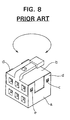
- a block connector is comprised of two housings: a lower housing a and an upper housing b.
- Lock portions d each formed with a lock hole c stand on four corners of the upper surface of the lower housing a, and the upper housing b is formed with lock projections e engageable with the lock holes c.
- the upper housing b is placed on the lower housing a while elastically deforming the respective lock portions d outward.
- the lock projections e are fitted into the lock hole c, with the result that the housings a, b are locked while being placed one over the other (see FIG. 8).
- the formed lock portions d can have only a small thickness.
- the lock portions d can satisfactorily function to prevent the disengagement of the housings a, b.
- the lock portions d may be elastically deformed, thereby disengaging the housings a, b.
- the present invention was developed in view of the above problem and an object thereof is to prevent the disengagement of housings by a simple construction.
- a block connector constructed by placing a plurality of connector housings one over another, in which the connector housings are locked by (preferably elastically locking) lock portions provided on at least one of the connector housings to be placed one over another with the other connector housing(s), wherein at least one projected portion and at least one (mating) recess which are engageable or fittable or mating with each other are provided on the surfaces of the connector housings which come together or are facing each other in the assembled state.
- the two connector housings are locked by the lock portions, and the projected portion and the recess provided on the surfaces of the housings which come together are engaged. Accordingly, the connector housings are unlikely to be displaced from each other or to be rotated with respect to each other, thereby preventing the action of such a force as to elastically deform the lock portions.
- the connector housings can be firmly locked only by a simple construction in which the projected portion and the recess are provided on the surfaces which come together.
- At least one of the projected portion and the recess is provided with a guide portion for guiding the engagement of the projected portion and the recess.
- the corresponding projected portion and recess are engaged with each other while being guided by the guide portion.
- the connector housings can be smoothly placed one over the other.
- the projected portion and the recess start engaging prior to the locking by the lock portions.
- the projected portion and the recess function to position the two connector housings, the assembling of the connector housing including the locking by the lock portions can be more smoothly performed.
- the projected portion and the recess are formed to have a noncircular cross section.
- the relative rotation of the connector housings can be prevented by providing the projected portion and the recess in at least one position.
- the lock portions are elastically locking the connector housings, the lock portions being preferably unitarily or integrally formed on at least one of the connector housings.
- At least two projected portions having different shapes from each other.
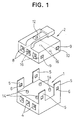
- FIGS. 1 to 4 show a first embodiment of the invention.
- a female block connector having a lower housing 1 and an upper housing 2 is shown.
- the lower housing 1 is made e.g. of a synthetic resin and has a shape of a substantially flat substantially rectangular parallelepiped. Inside the lower housing 1, e.g. three cavities 4 for accommodating unillustrated female terminal fittings are arranged side by side. On the upper surface of the lower housing 1, e.g. four lock portions 5 each formed with a lock hole 6 stand preferably at front and rear ends of left and right sides.
- the upper housing 2 is likewise made e.g. of a synthetic resin and has a shape of a substantially flat substantially rectangular parallelepiped. Inside the upper housing 2, e.g. three cavities 8 similar to the cavities 4 are arranged side by side.
- the upper housing 2 is formed to have a slightly smaller width than the lower housing 1 so as to be placed or placeable on the upper surface of the lower housing 1 while being fitted between the left and right lock portions 5.
- Lock projections 9 engageable with the lock holes 6 of the lock portions 5 are formed at portions of the upper housing 2 corresponding to the lock holes 6, preferably at front and rear ends of the left and right side surfaces of the upper housing 2.
- the lower surface of each lock projection 9 is a tapered surface 10.
- On the surface opposite to the lower housing 1, preferably on the upper surface of the upper housing 2 is formed a lock arm 12 for locking this female block connector with an unillustrated mating male connector.
- each projection 14 On the upper surface of the lower housing 1 are formed e.g. four preferably cylindrical projections 14 in positions preferably at a distance of the center of the connector housing, preferably in corner positions of substantially a rectangle.
- the end face of each projection 14 is bevelled to form a tapered guide surface 15.
- the housings 1, 2 are separately formed.
- the block connector is assembled as follows. After female terminal fittings are accommodated in the cavities 4, 8 of the respective housings 1, 2, the upper housing 2 is placed on the lower housing 1. The upper housing 2 is pressed while elastically deforming the respective lock portions 5 outward by the contact of the tapered surfaces 10 of the respective lock projections 9 with the upper ends of the lock portions 5.
- the guide surfaces 15 of the projections 14 of the lower housing 1 face the opening edges of the corresponding round holes 16 of the upper housing 2. If the lower and upper housings 1, 2 are displaced from each other, they are positioned by being guided by the guide surfaces 15, and the projections 14 are fitted into the round holes 16.
- the lock projections 9 substantially face the lock holes 6 of the lock portions 5 as shown in FIG. 4. Accordingly, the lock projections 9 are fitted or inserted into the lock holes 6 while the lock portions 5 are elastically restored to their original positions, with the result that the housings 1, 2 are disengageably locked. Since the four projections 14 provided on the upper surface of the lower housing 1 are fitted into the corresponding round holes 16 formed in the lower surface of the upper housing 2, a rotational movement of the housings 1, 2 is prevented and no such force to elastically deform the lock portions 5 acts. Of course, the displacement of the housings 1, 2 is also prevented.
- the housings 1, 2 can be firmly locked by a simple construction in which the projections 14 are provided on the upper surface of the lower housing 1 and the round holes 16 are provided in the lower surface of the upper housing 2. Further, by providing the guide surfaces 15 on the projections 14, the lower and upper housings 1, 2 are positioned before being locked by the respective lock portions 5, and the block connector can be more smoothly assembled.
- the guide surfaces 15 for positioning the lower and upper housings 1, 2 are formed at the opening edges of the round holes 16.
- the guide surfaces 15 may be provided on both the projections 14 and the round holes 16.
- the projections 14 are provided on the lower surface of the upper housing 2, and the round holes 16 into which the projections 14 are fittable are provided in the upper surface of the lower housing 1. As described above, it is sufficient to provide the guide surfaces 15 on either the projections 14 or the round holes 16.
- the projections 14 and the round holes 16 may be alternately provided in the lower and upper housings 1, 2.
Landscapes
- Connector Housings Or Holding Contact Members (AREA)
- Details Of Connecting Devices For Male And Female Coupling (AREA)
Applications Claiming Priority (2)
| Application Number | Priority Date | Filing Date | Title |
|---|---|---|---|
| JP30064796A JP3178359B2 (ja) | 1996-11-12 | 1996-11-12 | ブロックコネクタ |
| JP300647/96 | 1996-11-12 |
Publications (2)
| Publication Number | Publication Date |
|---|---|
| EP0841721A2 true EP0841721A2 (fr) | 1998-05-13 |
| EP0841721A3 EP0841721A3 (fr) | 1998-06-17 |
Family
ID=17887382
Family Applications (1)
| Application Number | Title | Priority Date | Filing Date |
|---|---|---|---|
| EP97119803A Withdrawn EP0841721A3 (fr) | 1996-11-12 | 1997-11-12 | Un connecteur par assemblage de blocs |
Country Status (3)
| Country | Link |
|---|---|
| US (1) | US5975961A (fr) |
| EP (1) | EP0841721A3 (fr) |
| JP (1) | JP3178359B2 (fr) |
Families Citing this family (9)
| Publication number | Priority date | Publication date | Assignee | Title |
|---|---|---|---|---|
| JP3320988B2 (ja) * | 1996-09-20 | 2002-09-03 | 矢崎総業株式会社 | 合体コネクタ |
| US6264501B1 (en) * | 1999-10-20 | 2001-07-24 | Tekcon Electronics Corp. | Connector assembly |
| JP3759870B2 (ja) * | 2000-10-27 | 2006-03-29 | 住友電装株式会社 | コネクタ |
| US20080003889A1 (en) * | 2006-06-30 | 2008-01-03 | Link Michael A | Modular I/O connector |
| JP2009087579A (ja) * | 2007-09-27 | 2009-04-23 | Panasonic Electric Works Co Ltd | 連結端子台 |
| JP2013137922A (ja) * | 2011-12-28 | 2013-07-11 | Tyco Electronics Japan Kk | 電気コネクタ |
| JP6237451B2 (ja) * | 2014-02-06 | 2017-11-29 | 株式会社オートネットワーク技術研究所 | 積層コネクタ |
| JP2016213093A (ja) * | 2015-05-11 | 2016-12-15 | アルプス電気株式会社 | 回転コネクタ |
| KR200495699Y1 (ko) * | 2020-06-26 | 2022-07-29 | 김학중 | 애완동물용 하네스를 기반한 캐어용품 |
Citations (4)
| Publication number | Priority date | Publication date | Assignee | Title |
|---|---|---|---|---|
| FR2271681A2 (en) * | 1974-05-14 | 1975-12-12 | Mars Actel | Electrical connector with removable cover - has cover fixing extension on rear face with coupling studs and holes |
| EP0470887A1 (fr) * | 1990-08-09 | 1992-02-12 | Société anonyme dite: LABINAL | Connecteur de dérivation |
| EP0600602A1 (fr) * | 1992-11-13 | 1994-06-08 | The Whitaker Corporation | Connecteur électrique pour un lecteur de carte |
| US5320555A (en) * | 1992-02-06 | 1994-06-14 | Yazaki Corporation | Module type connector assembly |
Family Cites Families (2)
| Publication number | Priority date | Publication date | Assignee | Title |
|---|---|---|---|---|
| DE3938964A1 (de) * | 1988-11-24 | 1990-05-31 | Yazaki Corp | Mehrfachstufenverbinder |
| JP2555733Y2 (ja) * | 1991-12-25 | 1997-11-26 | 住友電装株式会社 | コネクタ |
-
1996
- 1996-11-12 JP JP30064796A patent/JP3178359B2/ja not_active Expired - Fee Related
-
1997
- 1997-11-10 US US08/967,709 patent/US5975961A/en not_active Expired - Fee Related
- 1997-11-12 EP EP97119803A patent/EP0841721A3/fr not_active Withdrawn
Patent Citations (4)
| Publication number | Priority date | Publication date | Assignee | Title |
|---|---|---|---|---|
| FR2271681A2 (en) * | 1974-05-14 | 1975-12-12 | Mars Actel | Electrical connector with removable cover - has cover fixing extension on rear face with coupling studs and holes |
| EP0470887A1 (fr) * | 1990-08-09 | 1992-02-12 | Société anonyme dite: LABINAL | Connecteur de dérivation |
| US5320555A (en) * | 1992-02-06 | 1994-06-14 | Yazaki Corporation | Module type connector assembly |
| EP0600602A1 (fr) * | 1992-11-13 | 1994-06-08 | The Whitaker Corporation | Connecteur électrique pour un lecteur de carte |
Also Published As
| Publication number | Publication date |
|---|---|
| JPH10144382A (ja) | 1998-05-29 |
| JP3178359B2 (ja) | 2001-06-18 |
| US5975961A (en) | 1999-11-02 |
| EP0841721A3 (fr) | 1998-06-17 |
Similar Documents
| Publication | Publication Date | Title |
|---|---|---|
| US4959023A (en) | Electrical connector | |
| US5899762A (en) | Electrical connector having an insertion and extraction slide | |
| EP0624922B1 (fr) | Connecteur électrique | |
| US5484223A (en) | Double terminal stop connector | |
| US6053753A (en) | Sealed electrical connector assembly | |
| US5273462A (en) | Connector keying system | |
| JP3301329B2 (ja) | コネクタ | |
| US4479691A (en) | Connector assembly | |
| JPH07114131B2 (ja) | コネクタ | |
| US6764324B2 (en) | Lever-type connector assembly | |
| US5033980A (en) | Electrical connector with a double locking structure for terminals | |
| JP3003679B1 (ja) | コネクタ | |
| JPH054789B2 (fr) | ||
| US5975961A (en) | Block connector | |
| JPH04218281A (ja) | 電気コネクター | |
| US5651704A (en) | Electrical connector with terminal retainer | |
| US4932899A (en) | Electrical connector | |
| US5529426A (en) | Housing block-retaining construction | |
| JP3495908B2 (ja) | コネクタ装置 | |
| JPH10340757A (ja) | コネクタの係止構造 | |
| US6863463B2 (en) | Lever-type connector and connector assembly | |
| JPH11250985A (ja) | コネクタ嵌合構造 | |
| KR100228438B1 (ko) | 홀더부착 커넥터 | |
| JP3374363B2 (ja) | 低挿入力コネクタ | |
| JP2790971B2 (ja) | コネクタ |
Legal Events
| Date | Code | Title | Description |
|---|---|---|---|
| PUAI | Public reference made under article 153(3) epc to a published international application that has entered the european phase |
Free format text: ORIGINAL CODE: 0009012 |
|
| PUAL | Search report despatched |
Free format text: ORIGINAL CODE: 0009013 |
|
| 17P | Request for examination filed |
Effective date: 19971128 |
|
| AK | Designated contracting states |
Kind code of ref document: A2 Designated state(s): DE FR GB IT |
|
| AX | Request for extension of the european patent |
Free format text: AL;LT;LV;MK;RO;SI |
|
| AK | Designated contracting states |
Kind code of ref document: A3 Designated state(s): AT BE CH DE DK ES FI FR GB GR IE IT LI LU MC NL PT SE |
|
| AX | Request for extension of the european patent |
Free format text: AL;LT;LV;MK;RO;SI |
|
| 17Q | First examination report despatched |
Effective date: 19981028 |
|
| AKX | Designation fees paid |
Free format text: DE FR GB IT |
|
| RBV | Designated contracting states (corrected) |
Designated state(s): DE FR GB IT |
|
| GRAG | Despatch of communication of intention to grant |
Free format text: ORIGINAL CODE: EPIDOS AGRA |
|
| GRAG | Despatch of communication of intention to grant |
Free format text: ORIGINAL CODE: EPIDOS AGRA |
|
| GRAH | Despatch of communication of intention to grant a patent |
Free format text: ORIGINAL CODE: EPIDOS IGRA |
|
| STAA | Information on the status of an ep patent application or granted ep patent |
Free format text: STATUS: THE APPLICATION IS DEEMED TO BE WITHDRAWN |
|
| 18D | Application deemed to be withdrawn |
Effective date: 20020503 |