EP0841545B1 - Capteur de débit à tourbillon - Google Patents
Capteur de débit à tourbillon Download PDFInfo
- Publication number
- EP0841545B1 EP0841545B1 EP97810765A EP97810765A EP0841545B1 EP 0841545 B1 EP0841545 B1 EP 0841545B1 EP 97810765 A EP97810765 A EP 97810765A EP 97810765 A EP97810765 A EP 97810765A EP 0841545 B1 EP0841545 B1 EP 0841545B1
- Authority
- EP
- European Patent Office
- Prior art keywords
- measuring tube
- diaphragm
- sensor
- fluid
- electrode
- Prior art date
- Legal status (The legal status is an assumption and is not a legal conclusion. Google has not performed a legal analysis and makes no representation as to the accuracy of the status listed.)
- Expired - Lifetime
Links
Images
Classifications
-
- G—PHYSICS
- G01—MEASURING; TESTING
- G01F—MEASURING VOLUME, VOLUME FLOW, MASS FLOW OR LIQUID LEVEL; METERING BY VOLUME
- G01F1/00—Measuring the volume flow or mass flow of fluid or fluent solid material wherein the fluid passes through a meter in a continuous flow
- G01F1/05—Measuring the volume flow or mass flow of fluid or fluent solid material wherein the fluid passes through a meter in a continuous flow by using mechanical effects
- G01F1/20—Measuring the volume flow or mass flow of fluid or fluent solid material wherein the fluid passes through a meter in a continuous flow by using mechanical effects by detection of dynamic effects of the flow
- G01F1/32—Measuring the volume flow or mass flow of fluid or fluent solid material wherein the fluid passes through a meter in a continuous flow by using mechanical effects by detection of dynamic effects of the flow using swirl flowmeters
- G01F1/325—Means for detecting quantities used as proxy variables for swirl
- G01F1/3259—Means for detecting quantities used as proxy variables for swirl for detecting fluid pressure oscillations
- G01F1/3266—Means for detecting quantities used as proxy variables for swirl for detecting fluid pressure oscillations by sensing mechanical vibrations
Definitions
- the invention relates to a vortex flow sensor for Measurement of the flow velocity or the Volume flow rate one in a measuring tube in a Fluid flowing with one over one Diameter of the measuring tube arranged bluff body, the Creation of Kármán vortices.
- the vortex sensor either in Bluff body or separately in the opening of the wall of the Measuring tube are arranged.
- a swirl sensor is now desirable, but not only in the bluff body (as in US-A 47 16 770), but also in the wall of the measuring tube (as with GB-A 14 83 818) can be used.
- One object underlying the invention is therefore in being a vortex flow sensor with an inside of the bluff body and a vortex sensor Vortex flow sensor with one in the wall of the measuring tube specify fixed vortex sensor, the respective Vortex sensors have a largely identical structure should and as an independent component like a module can be produced.
- An advantage of the invention is that the Vortex sensor largely insensitive to the outside vibrations.
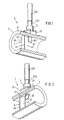
- FIGs. 1 and 2 and the overview serve perspective views, once in and once seen against the direction of flow, partly sliced vortex flow sensor 1 with an in and on a wall 21 of a measuring tube 2 fixed capacitive Vortex sensor 3.
- a diameter of the measuring tube 2 is in the Inside a bluff body 4 arranged with the measuring tube 2nd to form a first fixing point 41 shown and a hidden second fixing point firmly connected is. It is also possible to approach one of the fixing points dispense.
- the center of the opening 22 and the center of the Fixing point 41 lie on a surface line of the measuring tube.
- the bluff body 4 has an impact surface 42 against which the Operation of a fluid to be measured, e.g. a liquid, a Gas or a steam, inflows, and two side faces, of which only one (front) side surface 43 in the Fig. 1 and 2 can be seen. From the baffle 42 and the Side faces are formed of two tear-off edges, one of which only one (front) tear-off edge 44 completely and one (Rear) tear-off edge 45 can be seen in Fig. 1 are.
- a fluid to be measured e.g. a liquid, a Gas or a steam
- the shape and cross section of the bluff body 4 of FIG. 1 and 2 are essentially those of a straight triangular column, that is, a column with a triangular cross section. It However, other common forms of the bluff body can also be used be used in the invention.
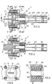
- FIGS. 3 to 7 Further details of the capacitive vortex sensor 3 after 1 and 2 are shown in Figs. 3 to 7, and each in the form of a sectional view. So show 3 and 4, the vortex sensor in two to each other by 90 ° offset longitudinal sections, FIGS. 5 and 7 two Cross sections and Fig. 6 shows a detail of the longitudinal section 3 in a slightly enlarged scale.
- the capacitive vortex sensor 3 has a covering the opening 22 in the wall 21 of the measuring tube 2 Membrane 33.
- This membrane has a fluid-facing first Surface and a fluid-facing second surface.
- the Membrane 33 closes the opening 22 in a fluid-tight manner, so that no fluid even at the highest allowable fluid pressure can reach the outer surface 21 of the measuring tube 2.
- the sensor flag is on the first surface of the membrane 33 31 attached, which is shorter than the diameter of the measuring tube 2nd is.
- the flat main surfaces 311, 312 are flush with the Surface line of the measuring tube 2 and can, as in Fig. 1st and 2 is hinted at, a small wedge form.
- a sleeve-shaped attached first electrode assembly 34 On the second surface of the membrane 33 is a sleeve-shaped attached first electrode assembly 34, the comprises at least one electrode 341. At the Transition point of the first electrode arrangement 34 to Membrane 33 there is a solid transition piece 342, that is about as high as the fluid-facing part 331 'of the Edge 331 of the membrane 33 and its diameter is approximately equal to the inside diameter of the sleeve of the first Electrode assembly 34 is.
- the housing cap 32 encloses the first electrode arrangement 34 and membrane 33 and is e.g. by means of four Screws 6, 7, 8, 9, attached to measuring tube 2.
- the Housing cap 32 contains a second electrode arrangement 35 with a first and a second counter electrode 351, 352. which are each approximately semicircular.
- the second electrode arrangement 35 is preferred as Prefabricated part manufactured according to his Completion in a corresponding blind hole 321 of the Housing cap 32, e.g. by shrinking, by means of a Press fit or by welding, is fixed.
- the second electrode arrangement 35 comprises, from the inside to the inside seen from the outside, the two counter electrodes 351, 352, one Insulating material ring 353 and a metal ring 354, which in the blind bore 321 of the housing cap 32 is seated.
- the extension 322 is with the remaining parts of the Housing tip 32 over a thin-walled, that is membrane-like Intermediate piece 323 connected, which is just above the ends of two electrode arrangements 34, 35.
- the Intermediate piece By means of the Intermediate piece are deflections of the extension 322, which, for example, due to vibrations acting on them from the outside are dependent on the electrode arrangements 34, 35 largely kept away.
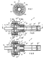
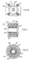
- FIG. 8 to 12 is an embodiment of a Vortex sensor shown in the when referencing the main bore of the bluff body mentioned in US Pat. No. 4,716,770 can be used, namely each Sectional representations selected. 8 and 9 show this move the vortex sensor in two to each other by 90 ° Longitudinal sections, FIGS. 10 and 12 two cross sections and 11 shows a detail of the longitudinal section of FIG. 8 in slightly enlarged scale.
- the capacitive vortex sensor 3 ' an the opening of the main bore in the bluff body and in the Wall of the measuring tube 2 'covering membrane 33'.
- This Membrane has a fluid-facing first surface and one fluid-facing second surface. The membrane 33 ' closes the opening 22 fluid-tight, so that even at a maximum permissible fluid pressure Shell surface 21 of the measuring tube 2 can reach.
- a sleeve-shaped attached first electrode assembly 34 ' comprises at least one electrode 341 '.
- the sensor sleeve 51 for the membrane 33 ' Transition piece 342 ' is about as high as the fluid-facing part Part 331 '' 'of the edge 331' of the membrane 33 '.
- the sensor sleeve 51 facing part 342 ''' 'of Transition piece 342 ' is slightly lower than part 342 " and whose diameter is equal to the outside diameter of the Sensor sleeve 51.
- a housing cap 32 ' encloses the first electrode arrangement 34 'and membrane 33' and is, e.g. by means of four screws 6 ', 7', 8 ', 9', attached to the measuring tube 2 '.
- the Housing cap 32 ' contains a second electrode arrangement 35 'with a first and a second counter electrode 351', 352 '. which are each approximately semicircular.
- the second electrode arrangement 35 ' is preferred as Prefabricated part manufactured according to his Completion in a corresponding blind hole 321 'of Housing cap 32 ', e.g. by shrinking or by means of a press fit is fixed.
- the second electrode arrangement 35 ' comprises, from the inside to the inside seen from the outside, the two counter electrodes 351 ', 352', one Insulating material ring 353 'and a metal ring 354', which in the blind bore 321 'of the housing cap 32' sits.
- the extension 322 ' is with the remaining parts of the Housing cap 32 'over a thin-walled, that is membrane-like Intermediate piece 323 'connected just above the ends of two electrode arrangements 34 ', 35'.
- the Intermediate piece By means of the Intermediate piece are deflections of the extension 322 ', which, for example, due to vibrations acting on them from the outside are dependent on the electrode arrangements 34 ', 35' largely kept away.
- the effects are which act on the measuring tube 2 or 2 'from the outside Accelerations, e.g. in the form of bumps or Vibrations, on the output of the above capacities May have compensated for the useful signal, largely as follows:
- the mass of the sensor flag 31 or the sensor sleeve 51 is larger than the mass of the first electrode arrangement 34 or 34 '.
- housing cap 32 or 32 ' is so rigid dimensioned so that they are at a maximum permissible acceleration acting on the measuring tube 2 or 2 ' bends.
- the membrane 33 transmits this greater force to the Electrode arrangement 34 in the opposite direction; the on it the resulting force is directed upwards, so that the electrode assembly moves up and thus a small change in capacity despite the vibration results.
Landscapes
- Physics & Mathematics (AREA)
- Fluid Mechanics (AREA)
- General Physics & Mathematics (AREA)
- Measuring Volume Flow (AREA)
- Measuring Fluid Pressure (AREA)
- Investigating Or Analyzing Materials By The Use Of Electric Means (AREA)
Claims (2)
- Capteur d'écoulement tourbillonnaire (1) pour mesurer la vitesse d'écoulement et/ou le débit volumétrique d'un fluide s'écoulant dans un tube de mesure (2) suivant une direction d'écoulement, comprenant :un corps (4) formant chicane disposé le long d'un diamètre du tube de mesure et relié au tube de mesure au niveau au moins d'un point de fixation (41), lequel corps formant chicane sert à produire des tourbillons de Karman,un détecteur capacitif (3) de tourbillons réagissant aux variations de pression produites par les tourbillons, lequel détecteur de tourbillons est monté en aval du corps formant chicane, dans une ouverture (22), côté paroi, du tube de mesure, rendant cette ouverture étanche en direction de la surface latérale dudit tube, ouverture dont le centre coïncide avec le centre du point de fixation sur une ligne latérale du tube de mesure, lequel détecteur présente les caractéristiques suivantes :une membrane (33) recouvrant l'ouverture, comprenant une première surface tournée vers le fluide et une seconde surface placée à l'opposé du fluide,un drapeau (31) de détecteur, mince et résistant aux flexions, fixé sur la première surface de la membrane, lequel drapeau est plus court que le diamètre et comprenant des surfaces principales plates (311, 312) qui sont alignées avec la ligne latérale du tube de mesure,un premier dispositif d'électrodes (34), en forme de douille, fixé sur la seconde surface de la membrane, lequel dispositif d'électrodes comprend au moins une électrode (341),un couvercle de boítier (32) fixé sur le tube de mesure et entourant le premier dispositif d'électrodes et la membrane, lequel couvercle de boítier contient un second dispositif d'électrodes (35) comprenant au moins une contre-électrode (351, 352),la masse du drapeau (31) du détecteur est rendue supérieure à la masse du premier dispositif d'électrodes (34),le moment d'inertie géométrique du drapeau du détecteur sur la première surface de la membrane est rendu sensiblement égal au moment d'inertie géométrique du premier dispositif d'électrodes sur la seconde surface de la membrane, etle couvercle (32) du boítier est dimensionné pour résister aux flexions, de façon telle qu'il ne se déforme pas lors d'une accélération admissible la plus forte possible agissant sur le tube de mesure (2).
- Capteur d'écoulement tourbillonnaire pour mesurer la vitesse d'écoulement et/ou le débit volumétrique d'un fluide s'écoulant dans un tube de mesure (2') suivant une direction d'écoulement, comprenant :un corps formant chicane disposé le long d'un diamètre du tube de mesure et relié au tube de mesure au niveau au moins d'un point de fixation, lequel corps formant chicane sert à produire des tourbillons de Karman, et un perçage principal s'étendant en direction de ce diamètre, ainsi qu'à travers le tube de mesure et au moins un perçage secondaire reliant le perçage principal au fluide,un détecteur capacitif (3') de tourbillons réagissant aux variations de pression produites par les tourbillons, lequel détecteur de tourbillons est monté dans le perçage principal, assurant l'étanchéité de la surface latérale du tube de mesure contre le fluide, lequel détecteur présente les caractéristiques suivantes :une membrane (33') recouvrant une extrémité, côté tube de mesure, du perçage principal, comprenant une première surface tournée vers le fluide et une seconde surface placée à l'opposé du fluide,une première douille (51) de détecteur résistant aux flexions et fixée sur la première surface de la membrane,un premier dispositif d'électrodes (34'), en forme de douille, fixé sur la seconde surface de la membrane, lequel dispositif d'électrodes comprend au moins une électrode (341'),un couvercle de boítier (32') fixé sur le tube de mesure et entourant le premier dispositif d'électrodes et la membrane, lequel couvercle de boítier contient un second dispositif d'électrodes (35') comprenant au moins une contre-électrode (351', 352'),la masse de la douille (51) du détecteur est rendue supérieure à la masse du premier dispositif d'électrodes (34'),le moment d'inertie géométrique de la douille du détecteur sur la première surface de la membrane est rendu sensiblement égal au moment d'inertie géométrique du premier dispositif d'électrodes sur la seconde surface de la membrane, etle couvercle (32') du boítier est dimensionné pour résister aux flexions, de façon telle qu'il ne se déforme pas lors d'une accélération admissible la plus forte possible agissant sur le tube de mesure (2').
Priority Applications (7)
| Application Number | Priority Date | Filing Date | Title |
|---|---|---|---|
| DK97810765T DK0841545T3 (da) | 1996-11-08 | 1997-10-10 | Hvirvelstrømsdetektor |
| EP97810765A EP0841545B1 (fr) | 1996-11-08 | 1997-10-10 | Capteur de débit à tourbillon |
| ES97810765T ES2133006T3 (es) | 1996-11-08 | 1997-10-10 | Detector de circulacion turbulenta. |
| DE59700147T DE59700147D1 (de) | 1996-11-08 | 1997-10-10 | Wirbelströmungsaufnehmer |
| US08/953,229 US6003384A (en) | 1996-11-08 | 1997-10-17 | Vortex flow sensor with a capacitive sensing element |
| CN97122235A CN1113219C (zh) | 1996-11-08 | 1997-11-07 | 涡流传感器 |
| JP9307126A JP3034833B2 (ja) | 1996-11-08 | 1997-11-10 | 渦流センサ |
Applications Claiming Priority (3)
| Application Number | Priority Date | Filing Date | Title |
|---|---|---|---|
| EP96117892 | 1996-11-08 | ||
| EP96117892 | 1996-11-08 | ||
| EP97810765A EP0841545B1 (fr) | 1996-11-08 | 1997-10-10 | Capteur de débit à tourbillon |
Publications (2)
| Publication Number | Publication Date |
|---|---|
| EP0841545A1 EP0841545A1 (fr) | 1998-05-13 |
| EP0841545B1 true EP0841545B1 (fr) | 1999-04-28 |
Family
ID=26142286
Family Applications (1)
| Application Number | Title | Priority Date | Filing Date |
|---|---|---|---|
| EP97810765A Expired - Lifetime EP0841545B1 (fr) | 1996-11-08 | 1997-10-10 | Capteur de débit à tourbillon |
Country Status (7)
| Country | Link |
|---|---|
| US (1) | US6003384A (fr) |
| EP (1) | EP0841545B1 (fr) |
| JP (1) | JP3034833B2 (fr) |
| CN (1) | CN1113219C (fr) |
| DE (1) | DE59700147D1 (fr) |
| DK (1) | DK0841545T3 (fr) |
| ES (1) | ES2133006T3 (fr) |
Cited By (2)
| Publication number | Priority date | Publication date | Assignee | Title |
|---|---|---|---|---|
| DE102013105363A1 (de) | 2013-05-24 | 2014-11-27 | Endress + Hauser Flowtec Ag | Wirbelströmungsmesssensor und Wirbelströmungsmessaufnehmer zur Messung der Strömungsgeschwindigkeit eines Fluids |
| DE102013013476A1 (de) | 2013-08-15 | 2015-02-19 | Endress + Hauser Flowtec Ag | Wirbelströmungsmesssensor und Wirbelströmungsmessaufnehmer zur Messung der Strömungsgeschwindigkeit eines fluids |
Families Citing this family (42)
| Publication number | Priority date | Publication date | Assignee | Title |
|---|---|---|---|---|
| EP0962749A1 (fr) | 1998-05-14 | 1999-12-08 | Endress + Hauser Flowtec AG | Procédé de calibration sèche des débimètres à tourbillon |
| CN1269011A (zh) * | 1998-05-14 | 2000-10-04 | 安德雷斯和霍瑟·弗罗泰克有限公司 | 干式校准涡街流量传感器的方法 |
| NL1009797C2 (nl) * | 1998-08-03 | 2000-02-04 | Tno | Inrichting voor het meten van de volumestroom van een fluïdum in een leiding. |
| US6352000B1 (en) * | 1998-08-12 | 2002-03-05 | Flowtec Ag | Vortex flow sensor |
| US6938496B2 (en) * | 2001-09-04 | 2005-09-06 | Endress + Hauser Flowtec Ag | Vortex flow pickup |
| EP1423663B1 (fr) * | 2001-09-04 | 2018-11-28 | Endress + Hauser Flowtec AG | Compteur de courant tourbillonnaire resistant a la corrosion |
| US6910387B2 (en) * | 2002-09-04 | 2005-06-28 | Endress + Hausser Flowtec Ag | Vortex flow sensor for measuring fluid flow through a flow tube |
| DE10249543A1 (de) * | 2002-10-23 | 2004-05-06 | Endress + Hauser Flowtec Ag, Reinach | Wirbelströmungsaufnehmer |
| EP1528371B1 (fr) * | 2003-11-03 | 2007-03-14 | Grundfos A/S | Ensemble pour installation de chauffage compact |
| DE102006034296A1 (de) * | 2006-07-21 | 2008-01-24 | Endress + Hauser Flowtec Ag | Meßsystem für ein in einer Prozeßleitung strömendes Medium |
| RU2419769C2 (ru) * | 2006-07-21 | 2011-05-27 | Эндресс+Хаузер Флоутек Аг | Измерительная система для среды, протекающей в технологическом трубопроводе |
| DE102007030699A1 (de) | 2007-06-30 | 2009-01-15 | Endress + Hauser Flowtec Ag | Meßsystem für ein in einer Prozeßleitung strömendes Medium |
| DE102007030690A1 (de) | 2007-06-30 | 2009-05-07 | Endress + Hauser Flowtec Ag | Meßsystem für ein in einer Prozeßleitung strömendes Medium |
| DE102007030700A1 (de) | 2007-06-30 | 2009-05-07 | Endress + Hauser Flowtec Ag | Meßsystem für ein in einer Prozeßleitung strömendes Medium |
| DE102007030691A1 (de) | 2007-06-30 | 2009-01-02 | Endress + Hauser Flowtec Ag | Meßsystem für ein in einer Prozeßleitung strömendes Medium |
| DE102007063372A1 (de) | 2007-12-30 | 2009-07-02 | Endress + Hauser Flowtec Ag | Meßsystem für ein in einer Prozeßleitung strömendes Medium |
| DE102007037166A1 (de) | 2007-08-07 | 2009-02-19 | Endress + Hauser Flowtec Ag | Meßgerät |
| US7647842B1 (en) * | 2008-07-25 | 2010-01-19 | Honeywell International Inc. | Pressure-based fluid flow sensor |
| DE102009002289A1 (de) | 2009-04-08 | 2010-10-14 | Endress + Hauser Flowtec Ag | Verfahren zum Ermitteln einer Periodendauer eines Meßsignals |
| JP5394506B2 (ja) * | 2009-12-24 | 2014-01-22 | ローズマウント インコーポレイテッド | 渦振動センサプレートを持つ渦流量計 |
| CN101979964B (zh) * | 2010-09-14 | 2012-11-21 | 涂强 | 可在线更换传感器的涡街流量计 |
| DE102012220505B4 (de) * | 2012-11-09 | 2016-10-20 | Gestra Ag | Überwachung eines Kondensatableiters |
| US9194729B2 (en) * | 2013-07-23 | 2015-11-24 | Yokogawa Corporation Of America | Flow area reduction techniques using a centralized streamlined body in vortex flowmeters |
| CN103727985A (zh) * | 2013-12-11 | 2014-04-16 | 天津大学 | 基于三轴加速度计的柔性涡街探头 |
| US9322683B2 (en) | 2014-05-12 | 2016-04-26 | Invensys Systems, Inc. | Multivariable vortex flowmeter |
| DE102014112558A1 (de) | 2014-09-01 | 2016-03-03 | Endress + Hauser Flowtec Ag | Sensorbaugruppe für einen Sensor, Sensor sowie damit gebildetes Meßsystem |
| DE102015116147A1 (de) | 2015-09-24 | 2017-03-30 | Endress + Hauser Flowtec Ag | Sensorbaugruppe für einen Sensor, Sensor sowie damit gebildetes Meßsystem |
| DE102015122553A1 (de) | 2015-12-22 | 2017-06-22 | Endress+Hauser Flowtec Ag | Wandlervorrichtung sowie mittels einer solchen Wandlervorrichtung gebildetes Meßsystem |
| DE102016104423A1 (de) * | 2016-03-10 | 2017-09-14 | Endress+Hauser Flowtec Ag | Sensorbaugruppe für einen Sensor, Sensor sowie damit gebildetes Meßsystem |
| DE102016124358A1 (de) | 2016-12-14 | 2018-06-14 | Endress + Hauser Flowtec Ag | Meßrohr für ein Meßgerät bzw. mittels eines solchen Meßrohrs gebildetes Meßgerät sowie Herstellverfahren für ein solches Meßrohr |
| DE102016125306A1 (de) | 2016-12-22 | 2018-06-28 | Endress+Hauser Flowtec Ag | Wirbelsensor für ein Vortex-Durchflussmessgerät, Vortex-Durchflussmessgerät und Verfahren zur Ermittlung eines Durchflusses |
| RU2672819C1 (ru) * | 2017-12-29 | 2018-11-19 | Акционерное общество "Научно-производственное объединение Измерительной техники" (АО "НПО ИТ") | Детектор вихрей |
| RU2681225C1 (ru) * | 2018-03-15 | 2019-03-05 | Акционерное общество "Научно-производственное объединение Измерительной техники" (АО "НПО ИТ") | Чувствительный элемент вихревого расходомера |
| RU2691285C1 (ru) * | 2018-08-30 | 2019-06-11 | Акционерное общество "Промышленная группа "Метран" | Преобразователь вихрей вихревого расходомера |
| DE102018132311A1 (de) | 2018-12-14 | 2020-06-18 | Endress + Hauser Flowtec Ag | Meßsystem zum Messen eines Strömungsparameters eines in einer Rohrleitung strömenden Fluids |
| CN110823297B (zh) * | 2019-11-26 | 2021-01-29 | 北京航空航天大学 | 振动环境下的动态流量测量装置及方法 |
| DE102020134264A1 (de) | 2020-12-18 | 2022-06-23 | Endress+Hauser Flowtec Ag | Sensor zum Erfassen von Druckschwankungen in einem strömenden Fluid sowie damit gebildetes Meßsystem |
| DE102021117707A1 (de) | 2021-07-08 | 2023-01-12 | Endress+Hauser Flowtec Ag | Meßsystem zum Messen eines Strömungsparameters eines in einer Rohrleitung strömenden fluiden Meßstoffs |
| DE102022105199A1 (de) | 2022-03-04 | 2023-09-07 | Endress+Hauser Flowtec Ag | Sensor sowie damit gebildetes Meßsystem |
| DE102022114875A1 (de) | 2022-06-13 | 2023-12-14 | Endress+Hauser SE+Co. KG | Messsystem |
| DE102022119145A1 (de) | 2022-07-29 | 2024-02-01 | Endress+Hauser Flowtec Ag | Anschlussschaltung für ein Feldgerät und Feldgerät |
| DE102022127160A1 (de) | 2022-10-18 | 2024-04-18 | Endress+Hauser Flowtec Ag | Sensorelement |
Family Cites Families (7)
| Publication number | Priority date | Publication date | Assignee | Title |
|---|---|---|---|---|
| GB1483818A (en) * | 1974-10-10 | 1977-08-24 | Fischer & Porter Ltd | Flowmeters |
| JPS57189015A (en) * | 1981-05-18 | 1982-11-20 | Yokogawa Hokushin Electric Corp | Measuring device for flow speed and flow rate |
| DE3544198A1 (de) * | 1985-12-13 | 1987-06-19 | Flowtec Ag | Wirbelstroemungsmesser |
| IN165010B (fr) * | 1986-02-03 | 1989-07-29 | Babcock & Wilcox Co | |
| DE4143202C1 (fr) * | 1991-12-30 | 1993-02-04 | Rota Yokogawa Gmbh & Co Kg, 7867 Wehr, De | |
| US5343762A (en) * | 1992-10-05 | 1994-09-06 | Rosemount Inc. | Vortex flowmeter |
| US5347873A (en) * | 1993-04-09 | 1994-09-20 | Badger Meter, Inc. | Double wing vortex flowmeter with strouhal number corrector |
-
1997
- 1997-10-10 EP EP97810765A patent/EP0841545B1/fr not_active Expired - Lifetime
- 1997-10-10 DK DK97810765T patent/DK0841545T3/da active
- 1997-10-10 DE DE59700147T patent/DE59700147D1/de not_active Expired - Lifetime
- 1997-10-10 ES ES97810765T patent/ES2133006T3/es not_active Expired - Lifetime
- 1997-10-17 US US08/953,229 patent/US6003384A/en not_active Expired - Lifetime
- 1997-11-07 CN CN97122235A patent/CN1113219C/zh not_active Expired - Lifetime
- 1997-11-10 JP JP9307126A patent/JP3034833B2/ja not_active Expired - Fee Related
Cited By (3)
| Publication number | Priority date | Publication date | Assignee | Title |
|---|---|---|---|---|
| DE102013105363A1 (de) | 2013-05-24 | 2014-11-27 | Endress + Hauser Flowtec Ag | Wirbelströmungsmesssensor und Wirbelströmungsmessaufnehmer zur Messung der Strömungsgeschwindigkeit eines Fluids |
| US9719819B2 (en) | 2013-05-24 | 2017-08-01 | Endress + Hauser Flowtec Ag | Vortex flow sensor for a vortex flow transducer having a flange shaped support device for supporting a membrane in a housing |
| DE102013013476A1 (de) | 2013-08-15 | 2015-02-19 | Endress + Hauser Flowtec Ag | Wirbelströmungsmesssensor und Wirbelströmungsmessaufnehmer zur Messung der Strömungsgeschwindigkeit eines fluids |
Also Published As
| Publication number | Publication date |
|---|---|
| EP0841545A1 (fr) | 1998-05-13 |
| JP3034833B2 (ja) | 2000-04-17 |
| ES2133006T3 (es) | 1999-08-16 |
| US6003384A (en) | 1999-12-21 |
| CN1113219C (zh) | 2003-07-02 |
| DE59700147D1 (de) | 1999-06-02 |
| JPH10160528A (ja) | 1998-06-19 |
| CN1192529A (zh) | 1998-09-09 |
| DK0841545T3 (da) | 1999-11-08 |
Similar Documents
| Publication | Publication Date | Title |
|---|---|---|
| EP0841545B1 (fr) | Capteur de débit à tourbillon | |
| EP0046965B1 (fr) | Procédé et appareil pour la détermination dynamique du débit massique independant de la densité | |
| WO2000009973A1 (fr) | Capteur d'écoulement turbulent | |
| EP2044392B1 (fr) | Système de mesure pour un milieu s'écoulant dans un conduit de traitement | |
| DE2458901C3 (de) | Strömungsmesser | |
| EP0350612B1 (fr) | Dispositif de mesure de pression et température | |
| DE3820418A1 (de) | Differenzdruckwandler | |
| DE2204269A1 (de) | Wirbelkörper-Strömungsmesser mit Innenfühler | |
| DE102006034296A1 (de) | Meßsystem für ein in einer Prozeßleitung strömendes Medium | |
| WO2014187629A1 (fr) | Capteur de mesure d'un écoulement tourbillonnaire et système de détection d'un écoulement tourbillonnaire permettant de mesurer la vitesse d'écoulement d'un fluide | |
| DE102011118921B4 (de) | Vortex-Durchflussmessgerät und diesbezügliche Faserdurchführung | |
| WO2004038344A1 (fr) | Debitmetre a tourbillons | |
| EP2546616B1 (fr) | Appareil de mesure de débit à vortex, capteur de pression pour appareil de mesure de débit à vortex et procédé de fabrication d'un tel capteur de pression | |
| DE102005001897B4 (de) | Ultraschallmessanordnung für den Einbau an einem Einrohranschlussstück in einer Rohrleitung | |
| EP0007553B1 (fr) | Dispositif de mesure de l'écoulement suivant le principe des tourbillons de Kármán | |
| EP1423663B1 (fr) | Compteur de courant tourbillonnaire resistant a la corrosion | |
| EP0654653A1 (fr) | Dispositif pour mesurer la vitesse d'un fluide | |
| DE102004029114A1 (de) | Ultraschall-Durchflussmesser | |
| DE3940474C1 (fr) | ||
| DE2712219C3 (de) | Strömungsmesser | |
| EP0565851A1 (fr) | Capteur ultrasonique pour la détermination du débit d'un liquide en écoulement | |
| DE102019008890A1 (de) | Durchflusszähler | |
| DE10243515A1 (de) | Sensor | |
| DE202006020144U1 (de) | Wirbeldurchflussmesser mit speziellen Sensormitteln zur Ermittlung des Durchflusswertes | |
| DE2453973C3 (de) | Strömungsmesser |
Legal Events
| Date | Code | Title | Description |
|---|---|---|---|
| PUAI | Public reference made under article 153(3) epc to a published international application that has entered the european phase |
Free format text: ORIGINAL CODE: 0009012 |
|
| AK | Designated contracting states |
Kind code of ref document: A1 Designated state(s): CH DE DK ES FR GB IT LI NL |
|
| 17P | Request for examination filed |
Effective date: 19980529 |
|
| GRAG | Despatch of communication of intention to grant |
Free format text: ORIGINAL CODE: EPIDOS AGRA |
|
| GRAG | Despatch of communication of intention to grant |
Free format text: ORIGINAL CODE: EPIDOS AGRA |
|
| GRAH | Despatch of communication of intention to grant a patent |
Free format text: ORIGINAL CODE: EPIDOS IGRA |
|
| 17Q | First examination report despatched |
Effective date: 19981012 |
|
| AKX | Designation fees paid |
Free format text: CH DE DK ES FR GB IT LI NL |
|
| RBV | Designated contracting states (corrected) |
Designated state(s): CH DE DK ES FR GB IT LI NL |
|
| GRAH | Despatch of communication of intention to grant a patent |
Free format text: ORIGINAL CODE: EPIDOS IGRA |
|
| GRAA | (expected) grant |
Free format text: ORIGINAL CODE: 0009210 |
|
| AK | Designated contracting states |
Kind code of ref document: B1 Designated state(s): CH DE DK ES FR GB IT LI NL |
|
| PG25 | Lapsed in a contracting state [announced via postgrant information from national office to epo] |
Ref country code: FR Free format text: LAPSE BECAUSE OF FAILURE TO SUBMIT A TRANSLATION OF THE DESCRIPTION OR TO PAY THE FEE WITHIN THE PRESCRIBED TIME-LIMIT Effective date: 19990428 |
|
| REG | Reference to a national code |
Ref country code: CH Ref legal event code: EP |
|
| ITF | It: translation for a ep patent filed |
Owner name: BARZANO' E ZANARDO MILANO S.P.A. |
|
| REF | Corresponds to: |
Ref document number: 59700147 Country of ref document: DE Date of ref document: 19990602 |
|
| REG | Reference to a national code |
Ref country code: ES Ref legal event code: FG2A Ref document number: 2133006 Country of ref document: ES Kind code of ref document: T3 |
|
| GBT | Gb: translation of ep patent filed (gb section 77(6)(a)/1977) |
Effective date: 19990730 |
|
| EN | Fr: translation not filed | ||
| REG | Reference to a national code |
Ref country code: DK Ref legal event code: T3 |
|
| PLBE | No opposition filed within time limit |
Free format text: ORIGINAL CODE: 0009261 |
|
| STAA | Information on the status of an ep patent application or granted ep patent |
Free format text: STATUS: NO OPPOSITION FILED WITHIN TIME LIMIT |
|
| 26N | No opposition filed | ||
| REG | Reference to a national code |
Ref country code: GB Ref legal event code: IF02 |
|
| PGFP | Annual fee paid to national office [announced via postgrant information from national office to epo] |
Ref country code: CH Payment date: 20061012 Year of fee payment: 10 |
|
| PGFP | Annual fee paid to national office [announced via postgrant information from national office to epo] |
Ref country code: IT Payment date: 20061031 Year of fee payment: 10 |
|
| REG | Reference to a national code |
Ref country code: CH Ref legal event code: PL |
|
| PG25 | Lapsed in a contracting state [announced via postgrant information from national office to epo] |
Ref country code: LI Free format text: LAPSE BECAUSE OF NON-PAYMENT OF DUE FEES Effective date: 20071031 Ref country code: CH Free format text: LAPSE BECAUSE OF NON-PAYMENT OF DUE FEES Effective date: 20071031 |
|
| PG25 | Lapsed in a contracting state [announced via postgrant information from national office to epo] |
Ref country code: IT Free format text: LAPSE BECAUSE OF NON-PAYMENT OF DUE FEES Effective date: 20071010 |
|
| PGFP | Annual fee paid to national office [announced via postgrant information from national office to epo] |
Ref country code: DK Payment date: 20121022 Year of fee payment: 16 |
|
| PGFP | Annual fee paid to national office [announced via postgrant information from national office to epo] |
Ref country code: ES Payment date: 20121026 Year of fee payment: 16 |
|
| PGFP | Annual fee paid to national office [announced via postgrant information from national office to epo] |
Ref country code: GB Payment date: 20131021 Year of fee payment: 17 |
|
| PGFP | Annual fee paid to national office [announced via postgrant information from national office to epo] |
Ref country code: NL Payment date: 20131022 Year of fee payment: 17 |
|
| REG | Reference to a national code |
Ref country code: DK Ref legal event code: EBP Effective date: 20131031 |
|
| PG25 | Lapsed in a contracting state [announced via postgrant information from national office to epo] |
Ref country code: DK Free format text: LAPSE BECAUSE OF NON-PAYMENT OF DUE FEES Effective date: 20131031 |
|
| REG | Reference to a national code |
Ref country code: ES Ref legal event code: FD2A Effective date: 20141107 |
|
| PG25 | Lapsed in a contracting state [announced via postgrant information from national office to epo] |
Ref country code: ES Free format text: LAPSE BECAUSE OF NON-PAYMENT OF DUE FEES Effective date: 20131011 |
|
| REG | Reference to a national code |
Ref country code: NL Ref legal event code: V1 Effective date: 20150501 |
|
| GBPC | Gb: european patent ceased through non-payment of renewal fee |
Effective date: 20141010 |
|
| PG25 | Lapsed in a contracting state [announced via postgrant information from national office to epo] |
Ref country code: GB Free format text: LAPSE BECAUSE OF NON-PAYMENT OF DUE FEES Effective date: 20141010 |
|
| PG25 | Lapsed in a contracting state [announced via postgrant information from national office to epo] |
Ref country code: NL Free format text: LAPSE BECAUSE OF NON-PAYMENT OF DUE FEES Effective date: 20150501 |
|
| PGFP | Annual fee paid to national office [announced via postgrant information from national office to epo] |
Ref country code: DE Payment date: 20161020 Year of fee payment: 20 |
|
| REG | Reference to a national code |
Ref country code: DE Ref legal event code: R071 Ref document number: 59700147 Country of ref document: DE |