EP0841526A2 - Umlaufförderer und damit ausgestatteter Ofen - Google Patents
Umlaufförderer und damit ausgestatteter Ofen Download PDFInfo
- Publication number
- EP0841526A2 EP0841526A2 EP97308923A EP97308923A EP0841526A2 EP 0841526 A2 EP0841526 A2 EP 0841526A2 EP 97308923 A EP97308923 A EP 97308923A EP 97308923 A EP97308923 A EP 97308923A EP 0841526 A2 EP0841526 A2 EP 0841526A2
- Authority
- EP
- European Patent Office
- Prior art keywords
- work piece
- array
- conveyor
- work pieces
- piece support
- Prior art date
- Legal status (The legal status is an assumption and is not a legal conclusion. Google has not performed a legal analysis and makes no representation as to the accuracy of the status listed.)
- Withdrawn
Links
- 238000010438 heat treatment Methods 0.000 claims abstract description 64
- 239000011347 resin Substances 0.000 claims abstract description 48
- 229920005989 resin Polymers 0.000 claims abstract description 48
- 230000000717 retained effect Effects 0.000 claims abstract description 11
- 238000003491 array Methods 0.000 claims description 38
- 238000000151 deposition Methods 0.000 abstract description 3
- 238000000429 assembly Methods 0.000 description 16
- 230000000712 assembly Effects 0.000 description 16
- 238000000034 method Methods 0.000 description 15
- 230000007246 mechanism Effects 0.000 description 8
- 230000008569 process Effects 0.000 description 8
- 239000011248 coating agent Substances 0.000 description 4
- 238000000576 coating method Methods 0.000 description 4
- 238000005461 lubrication Methods 0.000 description 4
- 238000012423 maintenance Methods 0.000 description 4
- 230000000284 resting effect Effects 0.000 description 4
- 238000003860 storage Methods 0.000 description 4
- 230000008439 repair process Effects 0.000 description 3
- 230000032258 transport Effects 0.000 description 3
- 238000004804 winding Methods 0.000 description 3
- 230000008901 benefit Effects 0.000 description 2
- 230000008859 change Effects 0.000 description 2
- 230000001351 cycling effect Effects 0.000 description 2
- 239000012199 graphalloy Substances 0.000 description 2
- 238000009413 insulation Methods 0.000 description 2
- 238000004519 manufacturing process Methods 0.000 description 2
- 238000001816 cooling Methods 0.000 description 1
- 230000008878 coupling Effects 0.000 description 1
- 238000010168 coupling process Methods 0.000 description 1
- 238000005859 coupling reaction Methods 0.000 description 1
- 238000001514 detection method Methods 0.000 description 1
- 238000011143 downstream manufacturing Methods 0.000 description 1
- 230000006870 function Effects 0.000 description 1
- 239000007789 gas Substances 0.000 description 1
- 230000005484 gravity Effects 0.000 description 1
- 238000005470 impregnation Methods 0.000 description 1
- 238000002955 isolation Methods 0.000 description 1
- 230000001050 lubricating effect Effects 0.000 description 1
- 238000003754 machining Methods 0.000 description 1
- 239000000463 material Substances 0.000 description 1
- 230000002572 peristaltic effect Effects 0.000 description 1
- 239000012466 permeate Substances 0.000 description 1
- 239000000047 product Substances 0.000 description 1
- 230000004044 response Effects 0.000 description 1
- 239000000126 substance Substances 0.000 description 1
Images


Classifications
-
- F—MECHANICAL ENGINEERING; LIGHTING; HEATING; WEAPONS; BLASTING
- F27—FURNACES; KILNS; OVENS; RETORTS
- F27B—FURNACES, KILNS, OVENS OR RETORTS IN GENERAL; OPEN SINTERING OR LIKE APPARATUS
- F27B9/00—Furnaces through which the charge is moved mechanically, e.g. of tunnel type; Similar furnaces in which the charge moves by gravity
- F27B9/14—Furnaces through which the charge is moved mechanically, e.g. of tunnel type; Similar furnaces in which the charge moves by gravity characterised by the path of the charge during treatment; characterised by the means by which the charge is moved during treatment
- F27B9/16—Furnaces through which the charge is moved mechanically, e.g. of tunnel type; Similar furnaces in which the charge moves by gravity characterised by the path of the charge during treatment; characterised by the means by which the charge is moved during treatment the charge moving in a circular or arcuate path
-
- F—MECHANICAL ENGINEERING; LIGHTING; HEATING; WEAPONS; BLASTING
- F26—DRYING
- F26B—DRYING SOLID MATERIALS OR OBJECTS BY REMOVING LIQUID THEREFROM
- F26B15/00—Machines or apparatus for drying objects with progressive movement; Machines or apparatus with progressive movement for drying batches of material in compact form
- F26B15/02—Machines or apparatus for drying objects with progressive movement; Machines or apparatus with progressive movement for drying batches of material in compact form with movement in the whole or part of a circle
- F26B15/04—Machines or apparatus for drying objects with progressive movement; Machines or apparatus with progressive movement for drying batches of material in compact form with movement in the whole or part of a circle in a horizontal plane
- F26B15/06—Machines or apparatus for drying objects with progressive movement; Machines or apparatus with progressive movement for drying batches of material in compact form with movement in the whole or part of a circle in a horizontal plane involving several planes, one above the other
-
- F—MECHANICAL ENGINEERING; LIGHTING; HEATING; WEAPONS; BLASTING
- F26—DRYING
- F26B—DRYING SOLID MATERIALS OR OBJECTS BY REMOVING LIQUID THEREFROM
- F26B25/00—Details of general application not covered by group F26B21/00 or F26B23/00
- F26B25/001—Handling, e.g. loading or unloading arrangements
- F26B25/003—Handling, e.g. loading or unloading arrangements for articles
-
- F—MECHANICAL ENGINEERING; LIGHTING; HEATING; WEAPONS; BLASTING
- F26—DRYING
- F26B—DRYING SOLID MATERIALS OR OBJECTS BY REMOVING LIQUID THEREFROM
- F26B3/00—Drying solid materials or objects by processes involving the application of heat
- F26B3/28—Drying solid materials or objects by processes involving the application of heat by radiation, e.g. from the sun
-
- F—MECHANICAL ENGINEERING; LIGHTING; HEATING; WEAPONS; BLASTING
- F26—DRYING
- F26B—DRYING SOLID MATERIALS OR OBJECTS BY REMOVING LIQUID THEREFROM
- F26B3/00—Drying solid materials or objects by processes involving the application of heat
- F26B3/32—Drying solid materials or objects by processes involving the application of heat by development of heat within the materials or objects to be dried, e.g. by fermentation or other microbiological action
- F26B3/34—Drying solid materials or objects by processes involving the application of heat by development of heat within the materials or objects to be dried, e.g. by fermentation or other microbiological action by using electrical effects
- F26B3/353—Resistance heating, e.g. using the materials or objects to be dried as an electrical resistance
-
- F—MECHANICAL ENGINEERING; LIGHTING; HEATING; WEAPONS; BLASTING
- F27—FURNACES; KILNS; OVENS; RETORTS
- F27B—FURNACES, KILNS, OVENS OR RETORTS IN GENERAL; OPEN SINTERING OR LIKE APPARATUS
- F27B9/00—Furnaces through which the charge is moved mechanically, e.g. of tunnel type; Similar furnaces in which the charge moves by gravity
- F27B9/02—Furnaces through which the charge is moved mechanically, e.g. of tunnel type; Similar furnaces in which the charge moves by gravity of multiple-track type; of multiple-chamber type; Combinations of furnaces
- F27B9/021—Furnaces through which the charge is moved mechanically, e.g. of tunnel type; Similar furnaces in which the charge moves by gravity of multiple-track type; of multiple-chamber type; Combinations of furnaces having two or more parallel tracks
-
- F—MECHANICAL ENGINEERING; LIGHTING; HEATING; WEAPONS; BLASTING
- F27—FURNACES; KILNS; OVENS; RETORTS
- F27B—FURNACES, KILNS, OVENS OR RETORTS IN GENERAL; OPEN SINTERING OR LIKE APPARATUS
- F27B9/00—Furnaces through which the charge is moved mechanically, e.g. of tunnel type; Similar furnaces in which the charge moves by gravity
- F27B9/30—Details, accessories or equipment specially adapted for furnaces of these types
-
- F—MECHANICAL ENGINEERING; LIGHTING; HEATING; WEAPONS; BLASTING
- F27—FURNACES; KILNS; OVENS; RETORTS
- F27D—DETAILS OR ACCESSORIES OF FURNACES, KILNS, OVENS OR RETORTS, IN SO FAR AS THEY ARE OF KINDS OCCURRING IN MORE THAN ONE KIND OF FURNACE
- F27D3/00—Charging; Discharging; Manipulation of charge
- F27D2003/0085—Movement of the container or support of the charge in the furnace or in the charging facilities
- F27D2003/0089—Rotation about a horizontal or slightly inclined axis
Definitions
- THIS INVENTION relates to a rotaly conveyor and particularly, but not exclusively, to such a conveyor for use in an oven for applying and curing resin on work pieces such as armatures or stators for electric motors.
- a rotary conveyor comprising an annular array of a plurality of circumferentially spaced work piece support members for receiving a corresponding plurality of work pieces; a first drive ring coaxially associated with said array for rotating said work pieces in said work piece support members, said drive ring being rotatable with respect to said array such that relative movement between said drive ring and said array causes the work pieces to rotate.
- the present invention provides a rotaly oven which comprises an annular array of a plurality of circumferentially spaced work piece support members for receiving a corresponding plurality of work pieces; a first driving ring coaxially associated with said array for rotating said work pieces in said work piece support members; said driving ring being movable relative to said array such that relative movement between said driving ring and said array rotates said work pieces.
- each array is carried in a generally cylindrical framework comprising a plurality of circularly arranged vertical support members.
- each array is carried on a corresponding annular platform. The structures supporting the annular arrays are rotated to carry the work pieces to locations where they are coated with the resin and heated by the heating elements.
- apparatus suitable for coating electric motor parts, such as armatures and stators, with an insulating resin.
- the apparatus comprises a plurality of axially spaced annular arrays, each array comprising a plurality of circumferentially spaced work piece support members.
- a plurality of heating elements is provided above the arrays and spaced about the periphery of the arrays, and a resin supply is provided for applying resin to the surface of the work pieces as they are carried in the support members.
- the invention also relates to a method for coating parts with a resin and/or for oven-curing such resin.
- the work piece support members are carried on annular platforms which are mounted on the outer race of a turret bearing. Teeth are provided on the outside surface of the outer race such that the outer race can be rotationally driven by a pinion which in turn rotates the annular platforms.
- the work piece support members are preferably rotated as they are transported about the oven.
- the work piece support members may include a collet assembly which is carried on a shaft.
- the shaft is rotated by a drive member which is in turm mounted on the inner race of the turret bearing.
- the turret bearing is driven independently of the outer race by a separate pinion drive to produce relative movement between the drive member and the work piece support members which in turn causes the collet to rotate.
- apparatus for depositing and curing resin on work pieces having a shaft therein includes a rotary conveyor rotatable within a compact oven.
- the apparatus as a whole is occasionally referred to as an "oven” and sometimes as a "rotary oven”.
- the apparatus preferably comprises a lower annular array having a plurality of generally circularly arranged, radially spaced work piece support members including collet assemblies.
- Each work piece support member has a sprocket mounted on its radially inward end and is shaped so as to receive a work piece in its radially outward end.
- the oven further comprises a lower ring coaxial with the lower array, the ring having a side-flexing chain mounted about its periphery such that the work piece support member sprockets mesh with the chain.
- the oven additionally includes a plurality of heating elements located above the periphery of the lower array such that the heating elements heat the work pieces retained in the collet assemblies, and a motor coupled to the lower ring for rotating the lower ring about the ring axis, whereby when the lower ring is rotated, the sprockets. collet assemblies and work pieces all rotate about their axes.
- the oven further comprises an indexing drive means coupled to the array for step-wise rotating the annular array, whereby as the array is indexed the work pieces are passed under the heating elements to thereby heat and cure the work pieces elements.
- the work piece support members are carried within a cylindrical frame which is mounted on the outer race of a turret bearing. Teeth can be provided on the outer surface of the race of the turret bearing such that the outer race can be rotationally driven by a pinion which in turn rotates the cylindrical frame.
- the work piece support members can be located in a far more precise manner than has been achieved with the chain conveyers used in conventional linear ovens. This allows for precise work piece location anywhere within the machine, and particularly at the load, unload and resin application stations.
- the invention further includes method for depositing and curing resin on work pieces having a shaft thereon.
- the method comprises the steps of providing a rotary oven having a first annular array comprising a plurality of generally circularly arranged, radially spaced work piece support members. Each work piece support member has a sprocket mounted radially inwardly and is adapted to receive a work piece.
- the oven further comprises a first driving ring coaxial with the first array, the ring having a chain mounted about its periphery such that the sprockets mesh with the chain, and a plurality of heating elements located above the periphery of the first array such that the heating elements heat the work pieces.
- the method further comprises the step of loading the work pieces in the work piece support members and rotating the first driving ring about the ring axis, whereby when the first ring is rotated, the sprockets. the work piece support members and the work pieces rotate about their axes.
- the method further includes the step of indexing the annular array, whereby as the array is indexed the work pieces are passed under the heating elements thereby heating and curing the work pieces.
- the present invention provides for interchangeable heating elements, which avoids having to store a number of different lengths of elements as spare parts in order to maintain the oven. Additionally, the heating element mountings of the present oven are relatively easy to remove. It is common in prior art ovens to provide for an approximately three foot wide opening to access a heating element that may be four or more feet long. In order to make repairs to these ovens. the operator may be forced to either work in close proximity to the operational heating elements to remove the faulty element, or must empty all of the work pieces out of the machine and shut it down for extended maintenance.
- the present invention provides relatively easy access to the heating
- the present invention also allows for easy maintenance of each individual work piece fixture. Furthermore, the current invention provides the capability for isolation of each of the varying heat zones within the oven from other heat zones in the oven. Thus. as the parts and mechanism heat up, the oven temperatures may be controlled and adjusted to maintain consistent and predictable temperatures within the different heating zones.
- the present machine allows for stoppages whereby work pieces can be unloaded from the oven. If the down-line operations are halted, removal and storing of the work pieces may be accommodated, which avoids having to provide a long storage conveyor.
- the present invention is a rotary oven, generally designated 10, having a plurality of axially spaced, vertically stacked arrays.
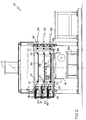
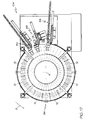
- Figure 1 shows a top plan view of the top array 34 of the oven 10.
- a hexagonal outer housing 11 encompasses the oven and several access doors 13 are provided about the periphery of the outer housing.
- a preferred embodiment of the oven utilizes three arrays: the lower array 30, middle array 32, and upper array 34.
- Each array 30, 32, 34 includes a series of radially spaced work piece support members 22 arranged in a generally circular manner.
- Each work piece support member 22 has a sprocket 17 on its radially inward end and a split bushing 19 on its radially outward end.
- the split bushing 19 is of a size so as to receive a shaft 21 of a work piece 20.
- the work piece support members 22 are collet assemblies.
- the invention is illustrated herein using collet assemblies as a type of work piece support member.
- any type of work piece support member which permits rotation of the work pieces including, for example. a pair of opposed V-blocks may be used to receive the work piece.
- the invention is illustrated and generally described herein using armatures a work pieces.
- a shaft may be loaded into the split bushing 19 and coupled to the stator.
- the oven further includes a lower annular ring 31, middle annular ring 33, and upper annular ring 35.
- Each ring 31, 33, 35 has a side-flexing chain 27 on its outer periphery which meshes with the sprockets 17 of the collet assemblies 22.
- the rings 31, 33, 35 are rotationally driven by collet rotational drive system 39.
- the rings 31, 33, 35 are rotationally driven, the sprocket 17 of the collet assemblies 22 are rotated.
- the rotation of the work piece support member 22 causes, in turn, rotation of the work pieces 20. This rotation allows for an even heating and curing of the work pieces, as well as even application of the resin.
- An advantage provided by this arrangement is that the side-flexing chain 27 does not require lubrication.
- the arrays 30, 32, 34 are supported on the outer race 28 of the turret bearing 26 (Fig. 3), Turret bearings useful in the invention are commercially available from Rotek and Kaydon.
- the outer race 28 is indexed by a pinion 29 that meshes with the teeth of outer race 28.
- the pinion 29 is driven by an electric motor drive (not shown). In this manner, the pinion rotates the outer race 28, and in turn indexes the lower array 30, the middle array 32 and the upper array 34. This indexing causes the work pieces contained in the collet assemblies 22 to travel in a circular path about the oven central axis A (Fig. 2).
- the electric motor drive is replaced by a commercially available indexer 41 (Fig. 2).
- the rings 31, 33, and 35 are rotatably driven by the drive system 39 which operates independently of the mechanism that indexes the arrays. Additionally. each of the rings may be driven independently of each other. Thus if desired it is possible to change the speed of rotation of the rings 31, 33, 35 during the short period of time that the annular arrays 30, 32, 34 are indexed in order to maintain a constant speed of work piece rotation. In existing ovens, it is not unusual for the rotation of the work pieces to speed up or slow down when the main index chains move the collets 22 with respect to work piece rotation drive chains. This can cause uncured resin to either be slung from the work piece as it rotates, or to sag to one side of the work piece.
- One example of a method for coating work pieces with resin is as follows.
- the work pieces are first loaded onto the work piece support members in the first array, travel nearly a complete rotation. are moved to a second array. again travel nearly a complete rotation, and finally are moved to a final array where curing is completed. After completing a nearly complete rotation on the final array.
- the work pieces 20 are removed from the oven 10.
- the first array is the lower array 30.
- the work pieces are then elevated to the middle array 32 (the second array) and finally to the upper array 34 (the final array).
- the arrays 30, 32, 34 may be rigidly coupled so that they rotate together.
- the arrays may be coupled independently by a gearing, which allows the arrays to index in different directions. All the indexing occurs while the work pieces 20 are continually rotated about their individual axes. In the manual loading configuration, indexing the final array in the opposite direction from the previous arrays provides work pieces to the operator on the same side of the transfer mechanism that the operator is on.
- Fig. 1 shows a top plan view of the lower array 30.
- a plurality of heating elements 12 are circumferentially spaced to make up the array.
- the heating elements 12 are used to preheat the work pieces before resin is applied to the work pieces. or to cure the resin after it is applied.
- the heating elements are preferably mounted on doors 16 that swing outwardly on posts 18 provided in the oven framework.
- the heating elements 12 are shown in Fig. 1 in their "open" position as heating elements 12'.
- Each work piece support member 22 is designed to receive and retain a work piece therein.
- a preferred work piece support member 22, shown in Figs. 6-8, is designed to receive the shaft 21 of a work piece 20.
- the collet assembly 22 may include a conventional collet or it may employ a split, spring-loaded bushing 80.
- the spring-loaded bushing 80 has a central hole 82 (Fig. 7) which is smaller in diameter than the shaft 21 of the work pieces 20.
- the bushing 80 comprises two opposed halves of the bushing and each of the two halves is spring biased radially inwardly (radially inward with respect to the collet assembly).
- the shaft 21 may be removed from the collet 22 upon application of sufficient force in the radially outward direction (radially outward with respect to the oven). Such force may be applied manually or by an unloading mechanism.
- the collet 22 is preferably designed such that it requires no lubrication. but instead uses a graphalloy bushing 200.
- the graphalloy bushings 200 requires no lubrication and function well at elevated temperatures. They are preferred over the use of ball bearings.
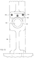
- the collet assemblies 22 are mounted within a cylindrical frame 90 formed of a plurality of circumferentially arranged columns 96 (See Figs. 4-5). Each column includes a row of vertically spaced of oval ports or windows 92 (Fig. 9) formed therein to receive a work piece support member 22. Each of the ports corresponds to a location to receive a collet located on the lower array 30, middle array 32 and upper array 34, respectively,
- the collet assemblies 22 are removable from the cylindrical frame 90 to allow replacement or repair of the collets 22.
- the cylindrical frame 90 is constructed of a series of vertical columns 96 (Figs. 9-10). Each column 96 may be mounted around the outer race of the turret bearing such that when a plurality of columns 96 are arranged side by side, a cylindrical frame 90 is thereby formed (See Figs. 4-5).
- the cylindrical frame 90 is continually rotationally indexed about its central axis A . In one embodiment, the oven indexes about every 5 seconds, and each array has 60 collets.
- each work piece support member 22 is retained in position in the oval ports 92 by a key 150 which traverses the length of the bore forming the port.
- the key 150 is retained by a hold-down bar 152 which traverses the front of the bore and is held in place by a pair of screws 154 (Fig. 12).
- the screws 154 and hold-down bar 152 are removed, thereby allowing removal of the key 150.
- the oval shape of the bore 92 then allows the work piece support member 22 to be pivoted upwardly to disengaged the sprocket from the side flexing chain 27. allowing the collet assembly to be removed.
- Figs. 6-8 show an alternate embodiment for retaining the collet assemblies 22 within the bores 92.
- the column 96 has an angled bore 98.
- the angled bore 98 receives an externally threaded cylinder 95 having a spring-loaded ball detente 94.
- the ball detente 94 extends below the upper surface of the bore 92 and is located so as to engage a groove 100 in the collet assembly 22. In this manner, the collet assembly 22 is retained within the vertical column 96.
- the threaded cylinder 95 and spring loaded ball 94 are removed and collet assembly 22 is tilted to disengage sprocket 17 from chain 27.
- Spring loaded ball 94 also acts as a compliant restraint to allow collet assembly 22 to pivot upwardly, as shown by angle 201 (Fig. 6) when the collet assemb1y is shifted out of position by a foreign object on the chain 27.
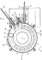
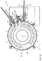
- the heating elements 12 are mounted on adapter plates 84 which are in turn mounted to rigid semicircular plates 87.
- Semicircular plates 87 are in turn mounted to pivot collars 86 which allow the heating element 12, heat shrouding, and insulation to be pivoted radially outward from the center of the oven. Reflective sheets may be placed within the heating chamber 14 to improve efficiency and increase the radiant energy absorbed by the work piece.
- Pivot collars 86 are axially slidably supported on posts 18. This arrangement allows the pivot collars 86 to be adjusted to vary the vertical distance between the heating elements 12 and the work pieces 20. Persons skilled in the art will appreciate that there are numerous ways of accomplishing this clampable adjustment.
- the adapter plates allow the heating chamber 14 to be casily removed in its entirety from the oven structure for servicing.
- the same general mounting structure is employed at the resin application stations, whereby the trickle nozzles are releasably secured to an adapter plate that allows the same adjustment and removal as the heating elements 12 described above.
- a commercially available computer or programmable controller in conjunction with the heating controls, and utilizing feedback from the heating elements, it is possible to vary the heating element temperatures in different sections of the oven based upon the knowledge of how many work pieces have been loaded into the oven, and tracking each work piece location over time.
- each heating element and its accompanying heating chamber is mounted on a large pivot post that allows each individual heating section to be swung tangentially away from the annular arrays. Heating elements can be safely changed or adjusted while the machine is cycling.
- each of the heating elements is identical and can be placed in any heating location of the oven. The invention enables the adjustment, removal and replacement of entire oven sections, including the heating element, the heat baffle shrouding and the insulation.
- a loading assembly 104 loads work pieces into the oven.
- Loading assembly 104 includes a horizontally oriented bar 106 having a generally v-shaped profile.
- a series of work pieces 20 may be manually or automatically placed upon the loading bar 106.
- a pusher bar (not shown) reciprocates along the length of the loader bar 106 to contact and push work pieces 20 on the loading bar towards the oven. In this manner, work pieces 20 are pushed down the end of the loader bar 106 towards the loader gripper 110. Once the work pieces reach the end of the loader bar 106, the loader gripper 110 grips, lifts, and inserts the work piece 20 into an associated work piece support member 22.
- the split bushing 19 of the collet assembly 22 receives the shalt 21 of the work piece 20.
- the position of the loader gripper assembly 110 as it inserts a work piece into the collet is shown in Fig. 14, and the position of the gripper when it lifts a work piece 20 off the bar 106 is shown as 110'.
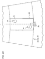
- the steps of the heating and curing process of a work piece 20 in one embodiment are as follows, and are illustrated in Figs. 15-17.
- a work piece 20 is first loaded into a work piece support member 22 resting on the lower array 30 by the loading assembly 104 as described above.
- the array is then step-wise indexed about its central axis A in the direction indicated by the arrow B .
- One work piece support member width is indexed at a time on the outer race 28 as was discussed in detail above.
- the UV curable resin is applied at location 160 as shown in Fig. 15.
- the UV curable resin is preferably applied to the exposed wires of an armature near the tangs of the commutator.
- a "flash cure” can be used to cure the resin at location 162.
- the flash cure can be accomplished using a UV light mounted below the lower array 30 and oriented such that the freshly applied resin is exposed to the UV light.
- resistance heat may be applied to the work piece by the brushes 102 at location 164.
- the brushes 102 are mounted within the oven in a releasably secured fashion. Preferably, a pair of brushes are mounted on either side of the path of the work piece 20.
- the resistance heating brushes 102 are spring biased inwardly to ensure contact with the work piece as the work pieces pass through the oven 10.
- the brushes are adjustable in the axial direction, with respect to the work piece, to accommodate work pieces of varying lengths.
- the resistant heating brushes 102 contact the work piece 20 and pass a current through the work piece. After the resistance heat is applied, the work piece 20 is then indexed the remaining revolution of the lower array 30 while passing under the heating elements 12, which continue to heat the work piece 20.
- Each work piece 20 is then elevated to the middle array 32, illustrated in Fig. 16.
- a transfer assembly 89 moves the work pieces from one array to another, and will he discussed in greater detail below.
- a work piece 20 continues to be heated by the radiant heating elements 12.
- the resin is applied to the work piece during the trickle stage.
- a plurality of resin nozzles can be located above the work pieces 20 at this stage in the oven.
- the resin is delivered from a resin reservoir (not shown to the nozzles by use of a peristaltic pump (not shown).
- a peristaltic pump not shown
- the application of the resin may be computer controlled to vary the application of resin for varying conditions and types of work pieces.
- the work piece is passed under the heating elements 12 to cure the resin.
- the work piece 20 is then removed from the middle array 32 and elevated to the upper array 34 by the transfer assembly 89. It is then placed in a work piece support member 22 on the upper array 34 and again indexed nearly a full revolution, while passing under the heating elements 12 to cure the resin, as shown in Fig. 17. At the end of a nearly full revolution at the upper array 34, the cured work piece is then unloaded from the oven by an unload assembly 119, which will be discussed in detail below.
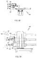
- the transfer assembly 89 shown in Figs. 18-19, is used to grip the work pieces 20 and transport them from a one array to another.
- Fig. 19 illustrates a transfer assembly having a pair of grippers 80, 82.
- lower transfer gripper 80 transports work pieces from work piece support members resting on the lower array 30 to the middle array 32.
- Middle transfer gripper 82 transports work pieces from work piece support members resting on the middle array 32 to the upper array 34.
- an upper transfer gripper (not shown) may be used to lift work pieces out of the work piece support members resting on the upper array 34 and place them on an auxiliary storage disk located above the upper array 34.
- Lower transfer gripper 80 is rotatably secured in a bearing such that it is able to "freewheel".
- the bearing allows the gripper to rotate to match the speed at which the work piece is rotating. Once the work piece 20 is detached from the work piece support member 22 and held solely by the gripper, the gripper and work piece will stop rotating. This rotation minimizes damage to the work piece 20.
- middle gripper 82 is rotated by a drive mechanism 135.
- the drive mechanism 135 is equipped with a form sprag one-way clutch such that it is able to free-wheel.
- the drive mechanism 135 can be set to rotate gripper 82 at a speed slightly slower that the rotational speed of the work piece support member 22.
- Gripper 82 will then slow down to the speed of the drive mechanism 135 when work piece 20 has been removed from the work piece support member assembly 22.
- the middle gripper 82 and lower gripper 80 are coupled in their vertical movement. In this manner, a work piece removed from the middle array 32 by the middle gripper 82 leaves an opening on the middle array which is immediately replaced by a work piece elevated from the lower array 30 by the lower gripper 80.
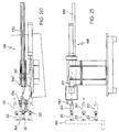
- the unload assembly 119 includes an unload gripper 130 which grips the work piece 20 and removes it from the split bushing 80 of the work piece support member 22.
- the work piece 20 is then moved radially away from the oven and placed in an unload bar 132 having a "V" shaped profile, similar to the loading bar 106 used with the loading assembly 104.
- the position of the unload gripper 130 after it deposits a work piece 22 on the unload bar 106 is shown in Fig. 20 as 130'.
- a row of work pieces 20 may be loaded upon the unload bar 132 and are moved radially away from the oven 10 as more work pieces are added. By the time the work pieces have been placed on the unload bar 132, the work pieces have been appropriately cured and can thereby be removed manually or automatically.
- a sensor may be provided at the end of the unload bar 132 to notify the operator when the bar is filled with work pieces.
- the oven 10 is described herein as having a lower array 30, middle array 32 and upper array 34.
- the work pieces are loaded on the lower level, work their way up to the upper level, and are then unloaded.
- the order of operations may be reversed.
- This alternate embodiment may be desirable because the UV light used to cure resin can be mounted above the work pieces on the upper level. In this manner, the UV light is located in a position which is easier to mount and access, and avoids having the freshly-applied resin drip on the UV light.
- a partial vacuum may be created within the trickle section 166 of the oven 10 when the resin is applied to the work piece 20.
- the partial vacuum increases the resin's saturation of the windings, and helps to fill up any voids within the windings.
- the work piece support members 22 may be angled upwardly during the trickle stage 166 so that gravity aids the resin to further permeate the windings.
- rings 38, 40 and 42 having beveled outer surfaces are utilized in place of the rings 31, 33, 35.
- the beveled outer surfaces of the rings 38, 40, 42 frictionally engage the correspondingly beveled heads 48 of the alternate collet assemblies 22'.
- the beveled heads 48 of the collet assemblies 22' are pressed into contact with the beveled rings by springs.
- Beveled rings 38, 40, 42 can also take the form of beveled gears, and the beveled heads 48 would also then be replaced with beveled gears.
- Rings 38, 40 and 42 are supported by inner race 36 of turret bearing 26.
- Inner race 36 is rotated by a pinion (not shown) that meshes with the teeth of inner race 36.
- the rotation of inner race 36 rotates the lower ring 38, which is mounted on inner race 36.
- the rotation of inner race 36 also rotates the rings 40 and 42 which are rigidly connected to the ring 38 by cylindrical columns 44 and 46. It should be noted that by placing another turret bearing on either column 44 or 46, rings 40 or 42 may be rotated at speeds independent from the other rings.
- Fig. 23 is a simplified view showing an embodiment of the removable mounting of collet body housing 61 on support rings 130, 132 and 134, respectively. In the operating position, the heads of the collet body mounting screws 77 are lodged in the lower portion of the keyhole slots 78 in the support rings.
- axial clamp screw 76 is loosened just enough to allow mounting screw heads 77 to move forward in keyhole slot 78 to a point where the screw head is clear to be lifted through the larger diametrical portion of the keyhole slot 78.
- Figs. 24-26 show an embodiment of an alternate work piece support member 22'.
- Gripper pins 66 hold the work piece 20 in place as it is indexed about the oven 10.
- an air cylinder or other similar apparatus (not shown) is mounted towards the center of the annular arrays and may press axially via rod 47 on bevel head 48.
- Bevel head 48 is an integral component with shaft 73, and thus the shaft 73 moves axially when the air cylinder presses on the bevel head 48. Shaft 73 thus compresses spring 51 until flat surface 74 of the bevel head 48 contacts the end 52 of center shalt 53.
- bevel head 48 is no longer in contact with bevel rings 138, 140 or 142, and thus is no longer being rotated.
- center shaft 53 is displaced axially with respect to the stationary outer shaft 75 and spring 54 is compressed between outer shaft 75 and split collar 55.
- Split collar 55 is recessed into annular groove 72 on center shaft 53.
- pin wedge head 63 (Fig. 24), being mounted to center shaft 53, also moves forward. The movement of center shaft 53 causes the gripper pins 66, which are slidably secured in holes 65, to move radially outward from center line 76.
- a pair of diametrically opposed angled slots 67 are located towards the rear of gripper pins 66 and contact with the front and rear vertical faces of outer shaft slotted head 62.
- the angled slots 67 are slidably retained in radial slots 64 located on the outer shaft of slotted head 62 (Fig. 24).
- Pin wedge head 63 is axially disposed from the stationary outer shaft slotted head 62, and gripper pins 66 are disposed radially from center line 76 allowing for work pieces of larger size to be secured or released.
- spring 54 urges center shaft 53 to move axially rearward with respect to stationary outer shaft 75.
- Pin wedge head 63 moves axially closer to outer shaft slotted head 62 and the gripper pins 66 move radially closer to center line 76.
- the gripper pins 66 will continue to move towards the center line 76 until they contact the work piece, at which point spring 54 continues to cause gripper pins to apply a gripping force on the work piece.
- spring 51 urges shaft 73 and bevel head 48 to make contact with bevel rings 38, 40 or 42.
- bevel head 48 makes contact with the bevel rings 130, 140, or 142 drive pin 56, securely mounted in shaft 73 and slidably retained in slot 57, imparts a torque about center line 76 that causes the inner shaft 53, along with outer shaft 75, to rotate about center line 76.
- This causes the gripper pins 66 and the work piece to be rotated.
- Outer shaft 75 rotates in hardened bearings 58, which in this embodiment of the invention are common drill bushings.
- Outer shaft 75 is also hardened and polished such that it can rotate freely in hardened bearings 58 for extended periods of time without the aid of lubricating substances, which minimizes the need for maintenance. Outer shaft 75 is axially retained in collet body housing 61 by thrust bearings 59 and split collars 60. Those skilled in the art will appreciate that any frictional engagement may be used to grip and retain the work pieces.
- exhaust stacks are placed at the top of the oven to exhaust gases from the oven.
- a fire detection and CO 2 fire response system may be used to detect and counteract any fires that may flare up within the oven.
- the work piece support members are rotated as they are transported in the oven.
- the work piece support members may be carried on a shaft which is rotated by a drive member which is mounted on the inner race of a second turret bearing.
- the inner surface of the second turret bearing has teeth that are driven by a second pinion, independent of the first turret bearing and first pinion.
- a third turret hearing, displaced axially from the second turret bearing, with yet another collet driving member and driven by a third pinion, will allow for work piece support members on separate annular arrays to be rotated at different speeds with respect to each other.
- the removal of an individual work piece support member for maintenance or replacement can be accomplished by the loosening of two mounting screws and the loosening of one central clamping screw. None of the screws need to be removed in order to facilitate work piece support member removal. Further, since the heating sections pivot open, a work piece support member can be removed while the machine is cycling. This avoids having to employ the product from the machine in order to service a work piece support member.
- annular arrays and work piece support members can be added axially above the processing arrays of the machine that will allow for the storage of in-process work pieces that can not be unloaded from the oven due to down-line stoppages.
- This particular feature eliminates the need for additional storage which requires additional floor space.
- the upper process arrays as a cooling chamber that will return the work pieces from the 375° F plus degrees of the oven to a workable ambient temperature. It is well known within the art that work piece temperatures above 120° F can greatly degrade the effectiveness and repeatability of many of the down-stream process after impregnation.
Landscapes
- Engineering & Computer Science (AREA)
- Mechanical Engineering (AREA)
- General Engineering & Computer Science (AREA)
- Life Sciences & Earth Sciences (AREA)
- Microbiology (AREA)
- Health & Medical Sciences (AREA)
- Biomedical Technology (AREA)
- Biotechnology (AREA)
- Molecular Biology (AREA)
- Processing And Handling Of Plastics And Other Materials For Molding In General (AREA)
Applications Claiming Priority (2)
| Application Number | Priority Date | Filing Date | Title |
|---|---|---|---|
| US3063496P | 1996-11-08 | 1996-11-08 | |
| US30634P | 1996-11-08 |
Publications (1)
| Publication Number | Publication Date |
|---|---|
| EP0841526A2 true EP0841526A2 (de) | 1998-05-13 |
Family
ID=21855157
Family Applications (1)
| Application Number | Title | Priority Date | Filing Date |
|---|---|---|---|
| EP97308923A Withdrawn EP0841526A2 (de) | 1996-11-08 | 1997-11-06 | Umlaufförderer und damit ausgestatteter Ofen |
Country Status (2)
| Country | Link |
|---|---|
| US (1) | US5990450A (de) |
| EP (1) | EP0841526A2 (de) |
Cited By (4)
| Publication number | Priority date | Publication date | Assignee | Title |
|---|---|---|---|---|
| WO2004044933A1 (de) * | 2002-11-12 | 2004-05-27 | Abb Technology Ag | Verfahren und anordnung zur aushärtung von spulen |
| WO2007032708A1 (en) * | 2005-09-15 | 2007-03-22 | Armen Vemirovich Nalbandjan | Bulk material dryer |
| CN103090652A (zh) * | 2012-12-24 | 2013-05-08 | 张家港市金太阳帽业有限公司 | 一种自动旋转羊毛绒帽子烘干装置 |
| CN119845010A (zh) * | 2025-03-21 | 2025-04-18 | 深圳市诚捷智能装备股份有限公司 | 一种烘烤装置及烘烤方法 |
Families Citing this family (10)
| Publication number | Priority date | Publication date | Assignee | Title |
|---|---|---|---|---|
| US6209225B1 (en) * | 1998-10-23 | 2001-04-03 | Danilo Villarroel | Rotatoty dryer for copper concentrate |
| US6397491B1 (en) * | 2000-10-19 | 2002-06-04 | Joseph J. Gilberti | Ultraviolet light curing apparatus |
| JP4617592B2 (ja) * | 2001-03-30 | 2011-01-26 | 澁谷工業株式会社 | 樹脂容器搬送システム |
| EP1610445A4 (de) * | 2003-09-10 | 2006-01-04 | Aisin Aw Co | Einrichtung und verfahren zur herstellung einer rotierenden elektrischen maschine |
| DE102005003802A1 (de) * | 2004-12-10 | 2006-06-14 | Nütro Maschinen- und Anlagenbau GmbH & Co. KG | Strahlungsgerät sowie Pulverauftragsstation und Anordnung zur Beschichtung von temperatursensiblen Materialien und Verfahren hierzu |
| KR101409581B1 (ko) | 2007-05-18 | 2014-06-20 | 쿠퍼비젼 인터내셔날 홀딩 캄파니, 엘피 | 콘텍트 렌즈를 형성하기 위한 열 경화 방법 및 시스템 |
| RU2350864C1 (ru) * | 2007-06-28 | 2009-03-27 | Юрий Борисович Данилов | Аппарат дисковый для термической обработки сыпучих материалов |
| US20090155958A1 (en) * | 2007-12-13 | 2009-06-18 | Boris Kolodin | Robust die bonding process for led dies |
| US20210010128A1 (en) * | 2018-03-29 | 2021-01-14 | Oerlikon Surface Solutions Ag, Pfäffikon | Device and method for selective vapor coating of a substrate |
| CN112179110B (zh) * | 2020-10-10 | 2022-02-18 | 内蒙古万众炜业科技环保股份公司 | 一种防破碎型煤生产用均匀受热烘干成型系统 |
Family Cites Families (18)
| Publication number | Priority date | Publication date | Assignee | Title |
|---|---|---|---|---|
| US2517360A (en) * | 1946-04-16 | 1950-08-01 | Singer Samuel | Broiler |
| US2574686A (en) * | 1948-08-26 | 1951-11-13 | Electrolux Corp | Method of impregnating electrical coils |
| US2549019A (en) * | 1949-10-17 | 1951-04-17 | Saunders Arthur | Roasting device |
| US3309982A (en) * | 1964-12-15 | 1967-03-21 | Frank H Surks | Cooking apparatus |
| US3390757A (en) * | 1965-08-25 | 1968-07-02 | Monsanto Co | Electrostatic printing apparatus |
| US3552299A (en) * | 1969-05-05 | 1971-01-05 | Tru Broil Corp | Rotary oven |
| US3732066A (en) * | 1970-11-16 | 1973-05-08 | Westinghouse Electric Corp | Oven for controlling heating and curing of resinous insulating material |
| US3782892A (en) * | 1972-05-19 | 1974-01-01 | Despatch Ind Inc | Ovens |
| US3744403A (en) * | 1972-10-24 | 1973-07-10 | J Castronuovo | Marshmallow toasting device |
| US4050889A (en) * | 1976-03-01 | 1977-09-27 | Belco Industries, Incorporated | Rotary oven |
| DE2706567C2 (de) * | 1976-03-18 | 1985-11-14 | Cincinnati Milacron Inc. (eine Ges. n.d. Gesetzen d. Staates Delaware), Cincinnati, Ohio | Greifvorrichtung für hohle Werkstücke |
| US4305329A (en) * | 1980-03-10 | 1981-12-15 | Fenoglio Bernard F | Turntable oven |
| US4969414A (en) * | 1985-06-10 | 1990-11-13 | General Electric Company | Apparatus for treating cores |
| US4967487A (en) * | 1988-04-25 | 1990-11-06 | Urquhart Gordon T | Oven for the curing and cooling of painted objects and method |
| US5275521A (en) * | 1991-07-03 | 1994-01-04 | Tokyo Electron Sagami Limited | Wafer transfer device |
| US5338189A (en) * | 1992-02-10 | 1994-08-16 | Murata Manufacturing Co., Ltd. | Heat treat furnace |
| US5254164A (en) * | 1992-06-15 | 1993-10-19 | Nordson Corp. | Coating system including indexing turret rotatable in the vertical and horizontal planes about a stationary shaft with loading and unloading of containers and closures from the edges of the turret |
| JP3354761B2 (ja) * | 1995-08-30 | 2002-12-09 | オリジン電気株式会社 | ディスク用被膜形成装置 |
-
1997
- 1997-11-05 US US08/964,704 patent/US5990450A/en not_active Expired - Fee Related
- 1997-11-06 EP EP97308923A patent/EP0841526A2/de not_active Withdrawn
Non-Patent Citations (1)
| Title |
|---|
| None |
Cited By (5)
| Publication number | Priority date | Publication date | Assignee | Title |
|---|---|---|---|---|
| WO2004044933A1 (de) * | 2002-11-12 | 2004-05-27 | Abb Technology Ag | Verfahren und anordnung zur aushärtung von spulen |
| WO2007032708A1 (en) * | 2005-09-15 | 2007-03-22 | Armen Vemirovich Nalbandjan | Bulk material dryer |
| CN103090652A (zh) * | 2012-12-24 | 2013-05-08 | 张家港市金太阳帽业有限公司 | 一种自动旋转羊毛绒帽子烘干装置 |
| CN119845010A (zh) * | 2025-03-21 | 2025-04-18 | 深圳市诚捷智能装备股份有限公司 | 一种烘烤装置及烘烤方法 |
| CN119845010B (zh) * | 2025-03-21 | 2025-06-17 | 深圳市诚捷智能装备股份有限公司 | 一种烘烤装置及烘烤方法 |
Also Published As
| Publication number | Publication date |
|---|---|
| US5990450A (en) | 1999-11-23 |
Similar Documents
| Publication | Publication Date | Title |
|---|---|---|
| US5990450A (en) | Rotary conveyor | |
| CA2280566C (en) | Portable journal turning lathe | |
| KR101642207B1 (ko) | 회전 가공기 및 회전 가공 방법 | |
| CN114999995A (zh) | 一种晶圆翻转机构 | |
| US4683020A (en) | Apparatus for storing and feeding tire beads | |
| CN118041018A (zh) | 一种电机线圈上漆生产线 | |
| CN111151906A (zh) | 压缩机装配焊接生产线及控制方法 | |
| SE525596C2 (sv) | Ringmaskin | |
| CN118801639B (zh) | 一种电机组装设备 | |
| CN110355914B (zh) | 全自动套膜机 | |
| CN217200171U (zh) | 一种用于电解转子测试机的转运装置 | |
| US4963391A (en) | Method of operating apparatus | |
| CN110665717A (zh) | 一种刹车盘喷涂设备 | |
| WO2001087745A1 (en) | Split drive component with maintained alignment | |
| US4790719A (en) | Method for storing and feeding tire beads | |
| CN214722123U (zh) | 一种ro泵前端盖组件自动组装设备 | |
| CN117583634B (zh) | 一种管道泵端部法兰钻孔装置 | |
| CN112496893B (zh) | 一种套筒阶梯上料式自动磨削加工系统及其工作方法 | |
| CN111960092B (zh) | 一种工业自动化组装机器人 | |
| CN121649849B (zh) | 一种轴类零件高效磨削加工设备 | |
| KR102769162B1 (ko) | 자동 공구 호닝기 및 이에 사용되는 캡 세트의 자동 탈부착 홀더 유닛 | |
| CN112497055A (zh) | 一种套筒阶梯上料式自动磨削加工系统 | |
| US4969414A (en) | Apparatus for treating cores | |
| CN121797571A (zh) | 一种立式旋涂自动化生产设备及工件点胶工艺 | |
| CN121289547B (zh) | 一种在加热盘上沿圆周取孔的钻孔装置及其钻孔工艺 |
Legal Events
| Date | Code | Title | Description |
|---|---|---|---|
| PUAI | Public reference made under article 153(3) epc to a published international application that has entered the european phase |
Free format text: ORIGINAL CODE: 0009012 |
|
| AK | Designated contracting states |
Kind code of ref document: A2 Designated state(s): AT BE CH DE DK ES FI FR GB GR IE IT LI LU MC NL PT SE |
|
| AX | Request for extension of the european patent |
Free format text: AL;LT;LV;MK;RO;SI |
|
| STAA | Information on the status of an ep patent application or granted ep patent |
Free format text: STATUS: THE APPLICATION IS DEEMED TO BE WITHDRAWN |
|
| 18D | Application deemed to be withdrawn |
Effective date: 20000601 |