EP0841120A1 - Clamping device - Google Patents
Clamping device Download PDFInfo
- Publication number
- EP0841120A1 EP0841120A1 EP97119042A EP97119042A EP0841120A1 EP 0841120 A1 EP0841120 A1 EP 0841120A1 EP 97119042 A EP97119042 A EP 97119042A EP 97119042 A EP97119042 A EP 97119042A EP 0841120 A1 EP0841120 A1 EP 0841120A1
- Authority
- EP
- European Patent Office
- Prior art keywords
- collet
- tapered
- balls
- transmission member
- peripheral surface
- Prior art date
- Legal status (The legal status is an assumption and is not a legal conclusion. Google has not performed a legal analysis and makes no representation as to the accuracy of the status listed.)
- Granted
Links
Images


Classifications
-
- B—PERFORMING OPERATIONS; TRANSPORTING
- B23—MACHINE TOOLS; METAL-WORKING NOT OTHERWISE PROVIDED FOR
- B23Q—DETAILS, COMPONENTS, OR ACCESSORIES FOR MACHINE TOOLS, e.g. ARRANGEMENTS FOR COPYING OR CONTROLLING; MACHINE TOOLS IN GENERAL CHARACTERISED BY THE CONSTRUCTION OF PARTICULAR DETAILS OR COMPONENTS; COMBINATIONS OR ASSOCIATIONS OF METAL-WORKING MACHINES, NOT DIRECTED TO A PARTICULAR RESULT
- B23Q3/00—Devices holding, supporting, or positioning work or tools, of a kind normally removable from the machine
- B23Q3/02—Devices holding, supporting, or positioning work or tools, of a kind normally removable from the machine for mounting on a work-table, tool-slide, or analogous part
-
- B—PERFORMING OPERATIONS; TRANSPORTING
- B25—HAND TOOLS; PORTABLE POWER-DRIVEN TOOLS; MANIPULATORS
- B25B—TOOLS OR BENCH DEVICES NOT OTHERWISE PROVIDED FOR, FOR FASTENING, CONNECTING, DISENGAGING OR HOLDING
- B25B5/00—Clamps
- B25B5/06—Arrangements for positively actuating jaws
- B25B5/061—Arrangements for positively actuating jaws with fluid drive
-
- B—PERFORMING OPERATIONS; TRANSPORTING
- B23—MACHINE TOOLS; METAL-WORKING NOT OTHERWISE PROVIDED FOR
- B23Q—DETAILS, COMPONENTS, OR ACCESSORIES FOR MACHINE TOOLS, e.g. ARRANGEMENTS FOR COPYING OR CONTROLLING; MACHINE TOOLS IN GENERAL CHARACTERISED BY THE CONSTRUCTION OF PARTICULAR DETAILS OR COMPONENTS; COMBINATIONS OR ASSOCIATIONS OF METAL-WORKING MACHINES, NOT DIRECTED TO A PARTICULAR RESULT
- B23Q1/00—Members which are comprised in the general build-up of a form of machine, particularly relatively large fixed members
- B23Q1/25—Movable or adjustable work or tool supports
- B23Q1/26—Movable or adjustable work or tool supports characterised by constructional features relating to the co-operation of relatively movable members; Means for preventing relative movement of such members
- B23Q1/28—Means for securing sliding members in any desired position
-
- B—PERFORMING OPERATIONS; TRANSPORTING
- B25—HAND TOOLS; PORTABLE POWER-DRIVEN TOOLS; MANIPULATORS
- B25B—TOOLS OR BENCH DEVICES NOT OTHERWISE PROVIDED FOR, FOR FASTENING, CONNECTING, DISENGAGING OR HOLDING
- B25B5/00—Clamps
- B25B5/06—Arrangements for positively actuating jaws
- B25B5/08—Arrangements for positively actuating jaws using cams
-
- B—PERFORMING OPERATIONS; TRANSPORTING
- B25—HAND TOOLS; PORTABLE POWER-DRIVEN TOOLS; MANIPULATORS
- B25B—TOOLS OR BENCH DEVICES NOT OTHERWISE PROVIDED FOR, FOR FASTENING, CONNECTING, DISENGAGING OR HOLDING
- B25B5/00—Clamps
- B25B5/14—Clamps for work of special profile
- B25B5/147—Clamps for work of special profile for pipes
-
- Y—GENERAL TAGGING OF NEW TECHNOLOGICAL DEVELOPMENTS; GENERAL TAGGING OF CROSS-SECTIONAL TECHNOLOGIES SPANNING OVER SEVERAL SECTIONS OF THE IPC; TECHNICAL SUBJECTS COVERED BY FORMER USPC CROSS-REFERENCE ART COLLECTIONS [XRACs] AND DIGESTS
- Y10—TECHNICAL SUBJECTS COVERED BY FORMER USPC
- Y10T—TECHNICAL SUBJECTS COVERED BY FORMER US CLASSIFICATION
- Y10T279/00—Chucks or sockets
- Y10T279/12—Chucks or sockets with fluid-pressure actuator
- Y10T279/1241—Socket type
- Y10T279/1249—Collet
-
- Y—GENERAL TAGGING OF NEW TECHNOLOGICAL DEVELOPMENTS; GENERAL TAGGING OF CROSS-SECTIONAL TECHNOLOGIES SPANNING OVER SEVERAL SECTIONS OF THE IPC; TECHNICAL SUBJECTS COVERED BY FORMER USPC CROSS-REFERENCE ART COLLECTIONS [XRACs] AND DIGESTS
- Y10—TECHNICAL SUBJECTS COVERED BY FORMER USPC
- Y10T—TECHNICAL SUBJECTS COVERED BY FORMER US CLASSIFICATION
- Y10T74/00—Machine element or mechanism
- Y10T74/20—Control lever and linkage systems
- Y10T74/20576—Elements
- Y10T74/20636—Detents
- Y10T74/2066—Friction
Definitions
- the present invention relates to a clamping device of the type adapted to hold and fix a rod by a collet and is a technique favorable for clamping, for example a support rod of a work support for a machine tool at a predetermined height.
- the taper angle for engagement could be set merely to a small value from about 6 degrees to about 10 degrees, so that the increasing of the holding and fixing force was limited.
- An object of the present invention is to provide a clamping device which is small in size but capable of exerting a large holding and fixing force.
- a clamping device is constructed as follows.
- a collet 10 is externally fitted onto a rod 4 inserted into a housing 2.
- a tapered internal peripheral surface 15 of a transmission member 14 faces a tapered external peripheral surface 11 of the collet 10 from outside.
- an annular tapered clearance C is formed between the tapered internal peripheral surface 15 and the tapered external peripheral surface 11.
- a large number of balls B are inserted into the annular tapered clearance C and arranged in a peripheral direction and in an axial direction.
- the transmission member 14 is moved by a first driving means F toward one end side of the axial direction to diametrically contract the collet 10 through the balls B by the transmission member 14.
- a stopper 22 prevents the diametrically contracted collet 10 from moving toward the one end side of the axial direction.
- the transmission member 14 is moved by a second driving means S toward the other end side of the axial direction to cancel the diametrical contraction of the collet 10.
- the balls B to be inserted into the annular clearance C are, in one case, inserted in the state kept in contact with one another in the peripheral direction and, in the other case, inserted in the state spaced apart at a predetermined interval in the peripheral direction. Further, it can be supposed that the balls B are, in one case, inserted in the state kept in contact with one another in the axial direction of the annular clearance C and, in the other case, inserted in the state spaced apart at a predetermined interval in the axial direction.
- the foregoing first driving means F may be constructed from a clamping piston 24 illustrated in Fig. 1, a clamping spring 31 illustrated in Fig. 4 or the likes.
- the foregoing second driving means S may be constructed from a return spring 28 illustrated in Fig. 1, a return piston 32 illustrated in Fig. 4 or the likes.
- the present invention functions, for example as shown in Fig. 1, as follows.
- the rod 4 is made free by the cancellation of the diametrical contraction of the collet 10 caused by an upward movement of the transmission member 14.
- the transmission member 14 When holding and fixing the rod 4, the transmission member 14 is driven downward by the clamping piston 24, the first driving means F. Thereupon, the tapered internal peripheral surface 15 of the transmission member 14 engages smoothly with the tapered external peripheral surface 11 of the collet 10 while rolling the balls B, and diametrically contracts the collet 10 received by the stopper 22. Thereby, the diametrically contracted collet 10 pushes a holding and fixing region A of the rod 4 in a diametrical direction to clamp the rod 4 at an illustrated height.
- the transmission member 14 When cancelling the foregoing clamping condition, the transmission member 14 is driven upward by the return spring 28, the second driving means S. Thereupon, the tapered internal peripheral surface 15 of the transmission member 14 moves upward smoothly while rolling the balls B, so that the foregoing engaging condition of the tapered external peripheral surface 11 of the collet 10 is cancelled. Thereby, the diametrical expansion of the collet 10 is allowed and the rod 4 is changed over to the foregoing unclamping condition.
- the present invention presents the following advantages.
- the present invention since the large number of balls B are inserted into the annular tapered clearance formed between the tapered surfaces of the transmission member and of the collet and arranged in the peripheral direction and in the axial direction, a friction acting between the foregoing tapered surfaces becomes a rolling friction, so that the friction force becomes remarkably reduced in comparison with a conventional sliding friction. Therefore, even if the taper angle for engagement is made small, the engagement between the tapered surfaces can be readily cancelled. Incidentally, according to the present invention, it becomes possible to reduce to about 2 degrees the taper angle for engagement which could be reduced merely to about 6 degrees conventionally.
- the clamping device can exert a large holding and fixing force and be manufactured in small size.
- the clamping device can be manufactured in smaller size as well as a consumption amount of the driving energy is reduced.
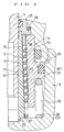
- Fig. 1 to Fig. 3 show a first embodiment of the present invention
- a work support 1 is clamped by a hydraulic force and its clamping is cancelled by a spring force.
- a housing 2 of the work support 1 comprises an upper end wall (a second end wall) 2a, a lower end wall (a first end wall) 2b and a barrel portion 2c and is fixedly secured to a table T by a plurality of tightening bolts 3 (herein, only one of which is illustrated).
- a support rod 4 is inserted into the housing 2 so as to be vertically movable. The support rod 4 is projected upward by an advancing spring 5, so that an attachment bolt 6 disposed in an upper portion of the support rod 4 is brought into contact with a workpiece W.
- a projecting length of the support rod 4 can be restricted by a restriction bolt 7.
- a holding and fixing region A is provided in a lower half portion of an external peripheral surface of the support rod 4, and a cylindrical collet 10 is externally fitted to the holding and fixing region A.
- the collet 10 has a tapered external peripheral surface 11 getting narrower upward and is adapted to be resiliently contracted diametrically by one slit 12 extending vertically.
- An annular transmission member 14 is disposed outside of the collet 10, so that a tapered internal peripheral surface 15 of the transmission member 14 faces the tapered external peripheral surface 11 of the collet 10 from above.
- gradients ⁇ of these tapered external peripheral surface 11 and tapered internal peripheral surface 15 are set to the same value. It is preferable that a taper angle (not illustrated) having a value double the value of the gradient ⁇ is within a range from about 2 degrees to about 10 degrees, and herein, it is set to about 4 degrees.
- a large number of balls B are inserted into an annular tapered clearance C formed between the tapered external peripheral surface 11 and the tapered internal peripheral surface 15. These balls B are inserted into the annular tapered clearance C being kept in contact with one another in the peripheral direction and piled up so as to contact with one another also in the axial direction.
- the balls B are pushed up to an upper flange 18 of the collet 10 by a pushing spring (a resilient member) 17 and arranged orderly.
- the collet 10 is pushed to a stopper 22 of the lower end wall 2b by a resilient force of a pushing rubber (another resilient member) 20 and an upper sleeve 21 and positioned in an unclamping lowered condition.
- a clamping piston 24 (first driving means F) is protruded from the transmission member 14 diametrically outward, so that a hydraulic actuation chamber 25 is formed above the piston 24 and a spring chamber 26 is formed thereunder.
- a supply and discharge port 27 for pressurized oil is connected to the actuation chamber 25, and a return spring 28 (second driving means S) is mounted into the spring chamber 26.
- a filter 30 is mounted to a breathing passage 29 of the spring chamber 26.
- the workpiece W is supported by the work support 1, for example according to the following procedure.
- the pressurized oil is discharged from the hydraulic actuation chamber 25.
- the piston 24 and the transmission member 14 are moved upward by the return spring 28 to cancel the diametrical contraction of the collet 10, and the support rod 4 is projected upward by the advancing spring 5.
- the workpiece W is brought in from above.
- a main body portion of the workpiece W is received by a support (not illustrated) as well as an illustrated projecting portion thereof is brought into contact with the attachment bolt 6 of the support rod 4 from above. Thereby, the support rod 4 is retreated to the illustrated height.
- the pressurized oil is supplied into the hydraulic actuation chamber 25.
- the transmission member 14 is moved downward by the hydraulic force acting from the actuation chamber 25 to the piston 24, so that the tapered internal peripheral surface 15 of the transmission member 14 engages smoothly with the tapered external peripheral surface 11 of the collet 10 while rolling the balls B to diametrically contract the collet 10 received by the stopper 22.
- the diametrically contracted collet 10 pushes the holding and fixing region A of the support rod 4 in a centripetal direction to hold and fix the support rod 4 at the illustrated height.
- the driving means such as the clamping piston 24 or the likes may be small in size even though it has a large supporting force (namely, a large holding and fixing force), so that the work support 1 can be manufactured compactly.
- the pressurized oil is discharged from the hydraulic actuation chamber 25.
- the piston 24 and the transmission member 14 are pushed upward by the return spring 28 and the tapered internal peripheral surface 15 of the transmission member 14 moves smoothly upward rolling the balls B, so that the pushing condition of the tapered external peripheral surface 11 of the collet 10 is cancelled.
- the collet 10 is diametrically expanded by its own resilient recovery force, so that the clamped condition of the support rod 4 can be cancelled.
- the tapered external peripheral surface 11 Since the tapered external peripheral surface 11, the tapered internal peripheral surface 15 and the balls B merely undergo rolling resistances very small in comparison with sliding resistance and additionally produce little aged deterioration when being subjected to a hardening treatment such quenching and the likes, their lives are long. Therefore, the work support 1 can be used for a long period of time with maintenance free.
- the balls B are accurate in diametral dimension and inexpensively available in market, the assembly accuracy of the work support 1 can be improved and also the manufacturing cost can be reduced.
- the transmission member 14 and the piston 24 may be formed as separate members instead of the integral member formed as illustrated. Further, an urging force of the return spring 28 may be applied to the transmission member 14 instead of applying to the piston 24.
- the pushing spring 17 may be arranged so as to push the balls B downward.
- a ball receiving flange is formed in a lower portion of the transmission member 14.
- the resilient member for pushing the balls B may be formed from rubber or the likes instead of the spring 17, otherwise it may be omitted.
- another resilient member for pushing the collet 10 to the stopper 22 may be such a spring as a coned disc spring, a compression coil spring or the likes instead of the pushing rubber 20.
- Fig. 4 shows a second embodiment of the present invention and is a view corresponding to Fig. 1.
- the same component members as those of the first embodiment are designated by the same characters in principle for explanation.
- the work support 1 is clamped by a spring force and its clamping is cancelled by a hydraulic force.
- the transmission member 14 is urged downward by a clamping spring 31 (the first driving means F).
- the transmission member 14 is moved upward by an annular return piston 32 against the clamping spring 31.
- the piston 32 is externally fitted to a lower cap 33 constructing a bottom portion of the lower wall 2b of the housing 2, and the stopper 22 is formed in the lower cap 33.
- the plurality of balls B inserted into the annular tapered clearance C are arranged orderly at a midway height by an upper spring 34 and a lower one 35, the resilient members.
- the return piston 32 and the transmission member 14 may be constructed integrally instead of being constructed separately.
- Fig. 5 to Fig. 8 show modifications of the present invention respectively. Also in these respective modifications, the same component members as those of the above-mentioned respective embodiments are designated by the same characters for explanation in principle.
- a first modification of Fig. 5 is a partially enlarged view corresponding to Fig. 1, and the plurality of balls B pushed up by the pushing springs 17 with annular spacers 37 mounted between the balls B, B piled up within the annular tapered clearance C are received by the upper sleeve 21 through a ring 38. Thereby, it becomes possible to reduce the rolling resistance by preventing interferences between the balls B, B.
- FIG. 6 A second modification of Fig. 6 is a view corresponding to Fig. 2, wherein arc grooves 40 extending in the axial direction (in the direction intersecting at right angles with respect to this paper surface) are formed in the tapered external peripheral surface 11 of the collet 10, and the balls B are held in the respective arc grooves 40.
- FIG. 7 A third modification of Fig. 7 is a schematic view corresponding to Fig. 3, and the plurality of slits 12 are formed in the collet 10.
- FIG. 8 A fourth modification of Fig. 8 is a schematic view corresponding to Fig. 3, wherein the collet 10 comprises a plurality of split members 10a, and diametrical contraction of the adjacent split members 10a, 10a are adapted to be cancelled by a spring 41 for diametrical expansion.
- Numeral 42 designates a guide pin.
- the split members 10a may be also so constructed that the diametrical contraction can be cancelled by their own resilient return forces.
- the means for advancing the support rod 4 upward may use rubber or other kinds of resilient members, or compressed air instead of the advancing spring 5.
- the pressurized fluid to be supplied to the actuation chamber 25 (36) may be a gas such as air instead of a liquid such as the pressurized oil.
- the work support 1 may be also so placed that its axis extends in a horizontal direction or in an inclined direction instead of being so placed that the axis of the support rod 4 extends in the vertical direction.
- clamping device of the present invention may be applied to a use for locking and unlocking a piston rod of a fluid-pressure cylinder apparatus or a use for locking and unlocking a rod attached to a moving body such as an elevator, a conveyance pallet and so on instead of being applied to the work support 1.
Abstract
Description
Claims (6)
- A clamping device comprising:a housing (2) having a first end and a second end, a rod (4) being inserted into the housing (2);a collet (10) having a tapered external peripheral surface (11) and being externally fitted onto the rod (4);a transmission member (14) having a tapered internal peripheral surface (15) facing the tapered external peripheral surface (11) from outside;an annular tapered clearance (C) formed between the tapered internal peripheral surface (15) and the tapered external peripheral surface (11);a large number of balls (B) inserted into the annular tapered clearance (C) and arranged in a peripheral direction and in an axial direction;a first driving means (F) for diametrically contracting the collet (10) through the balls (B) by moving the transmission member (14) toward the first end;a stopper (22) for preventing the diametrically contracted collet (10) from moving toward the first end, and;a second driving means (S) for cancelling the diametrical contraction of the collet (10) by moving the transmission member (14) toward the second end.
- A clamping device as set forth in claim 1, which further comprises a resilient member (17) for pushing the large number of balls (B) in the axial direction of the annular tapered clearance (C).
- A clamping device as set forth in claim 1 or claim 2, which further comprises another resilient member (20) for pushing the collet (10) to the stopper (22).
- A clamping device as set forth in any one of claims 1 through 3, which further comprises a spacer (37) mounted between the balls (B), (B) arranged in the axial direction.
- A clamping device as set forth in any one of claims 1 through 4, wherein the first driving means (F) includes a clamping piston (24), and the second driving means (S) includes a return spring (28).
- A clamping device as set forth in any one of claims 1 through 4, wherein the first driving means (F) includes a clamping spring (31), and the second driving means (S) includes a return piston (32).
Applications Claiming Priority (3)
| Application Number | Priority Date | Filing Date | Title |
|---|---|---|---|
| JP29917296 | 1996-11-12 | ||
| JP299172/96 | 1996-11-12 | ||
| JP29917296A JP3617745B2 (en) | 1996-11-12 | 1996-11-12 | Collet clamp |
Publications (3)
| Publication Number | Publication Date |
|---|---|
| EP0841120A1 true EP0841120A1 (en) | 1998-05-13 |
| EP0841120B1 EP0841120B1 (en) | 2004-12-15 |
| EP0841120B2 EP0841120B2 (en) | 2007-10-17 |
Family
ID=17869073
Family Applications (1)
| Application Number | Title | Priority Date | Filing Date |
|---|---|---|---|
| EP97119042A Expired - Lifetime EP0841120B2 (en) | 1996-11-12 | 1997-10-31 | Clamping device |
Country Status (6)
| Country | Link |
|---|---|
| US (1) | US5979267A (en) |
| EP (1) | EP0841120B2 (en) |
| JP (1) | JP3617745B2 (en) |
| KR (1) | KR100440809B1 (en) |
| DE (1) | DE69731933T3 (en) |
| TW (1) | TW371277B (en) |
Cited By (4)
| Publication number | Priority date | Publication date | Assignee | Title |
|---|---|---|---|---|
| EP1336450A2 (en) * | 2002-02-13 | 2003-08-20 | Kabushiki Kaisha Kosmek | Cylinder assembly |
| WO2005050030A1 (en) * | 2003-11-14 | 2005-06-02 | Nexen Group, Inc. | Motion control apparatus with backlash reduction |
| WO2007078807A1 (en) * | 2005-12-16 | 2007-07-12 | Hr Textron, Inc. | Pneumatic collet |
| CN102896493A (en) * | 2012-10-18 | 2013-01-30 | 无锡海特精密模具有限公司 | Assembling device of automobile air conditioner fin die hobbing cutter |
Families Citing this family (24)
| Publication number | Priority date | Publication date | Assignee | Title |
|---|---|---|---|---|
| US6755101B1 (en) | 2003-05-29 | 2004-06-29 | Babcock & Wilcox Canada Ltd. | Low profile in-line beveler |
| US7059457B2 (en) * | 2003-10-06 | 2006-06-13 | Lee Lanny R | Expansion motor |
| US7735815B2 (en) | 2004-03-27 | 2010-06-15 | Airbus Deutschland Gmbh | Holding device for generating a retaining pressure on an airplane component |
| DE102004015172B4 (en) * | 2004-03-27 | 2016-06-09 | Airbus Operations Gmbh | Holding device for generating a holding pressure on an aircraft component |
| US7258348B2 (en) * | 2004-12-16 | 2007-08-21 | General Electric Company | Machining fixture for centering and holding workpiece |
| JP4438661B2 (en) * | 2005-03-28 | 2010-03-24 | 富士通株式会社 | Welding apparatus and member gripping mechanism |
| WO2007085002A2 (en) * | 2006-01-20 | 2007-07-26 | Fori Automation, Inc. | Quick-disconnect work support assembly |
| JPWO2007132809A1 (en) * | 2006-05-16 | 2009-09-24 | 株式会社コスメック | Work support |
| US9446462B2 (en) * | 2008-03-10 | 2016-09-20 | Brasscraft Manufacturing Company | Material cutter clamping collet |
| US8087845B2 (en) * | 2008-05-22 | 2012-01-03 | GM Global Technology Operations LLC | Integrated locking assembly for reconfigurable end-effectors |
| TWI451933B (en) * | 2009-03-26 | 2014-09-11 | Hon Hai Prec Ind Co Ltd | Clamping apparatus |
| US8702340B2 (en) * | 2010-01-27 | 2014-04-22 | GM Global Technology Operations LLC | Integrated linear and rotary locking device |
| JP5557630B2 (en) * | 2010-07-13 | 2014-07-23 | パスカルエンジニアリング株式会社 | Clamping device |
| CN102092058A (en) * | 2010-11-19 | 2011-06-15 | 太原重工股份有限公司 | Die holder clamping device for hydraulic trimmer |
| WO2015173884A1 (en) * | 2014-05-13 | 2015-11-19 | 三菱電機株式会社 | Brake device for elevator hoist |
| US10160038B1 (en) * | 2014-08-29 | 2018-12-25 | Logan Clutch Corporation | Multi-spindle machine control system |
| US10799992B2 (en) * | 2015-09-01 | 2020-10-13 | Vektek, Inc. | Clamping mechanism for hydraulic work support |
| DE202015008601U1 (en) * | 2015-12-15 | 2016-01-28 | Horst Knäbel | Clamping device for workpieces |
| ITUB20160781A1 (en) * | 2016-01-27 | 2017-07-27 | Hydroblock S R L | DEVICE FOR LOCKING PIECES ON MACHINE TOOLS |
| DE202016005535U1 (en) * | 2016-09-09 | 2017-12-18 | Ludwig Ehrhardt Gmbh | Supporting element, in particular for supporting a workpiece |
| JP7193122B2 (en) * | 2018-10-22 | 2022-12-20 | 株式会社コスメック | work support |
| CN112139976B (en) * | 2020-10-14 | 2022-05-13 | 佛山市豫先达机械有限公司 | Multi-surface polishing device for machining transmission shaft |
| CN112372006B (en) * | 2020-11-17 | 2022-06-21 | 三门核电有限公司 | Shielding main pump body internal stay outward clamping type flange face machining device |
| KR102598801B1 (en) * | 2022-01-03 | 2023-11-07 | 강문식 | Work support |
Citations (7)
| Publication number | Priority date | Publication date | Assignee | Title |
|---|---|---|---|---|
| NL240863A (en) * | 1900-01-01 | |||
| US1840470A (en) * | 1929-02-19 | 1932-01-12 | Hays Mfg Co | Work holder |
| GB548690A (en) * | 1941-10-04 | 1942-10-20 | British Timken Ltd | Improvements in expanding chucks, mandrels or arbors |
| GB1066211A (en) * | 1963-04-01 | 1967-04-26 | Samuel Osborn & Company Ltd | Improvements in and relating to chucks |
| DE1765353B1 (en) * | 1968-05-04 | 1972-06-08 | Aeg Elotherm Gmbh | Clamping device for locking a hydraulically, pneumatically or electrically axially movable piston rod, in particular on electrically abrasive machines |
| DE3707046A1 (en) * | 1987-03-05 | 1988-09-15 | Haenchen Kg Herbert | Clamping device for rods |
| EP0561395A1 (en) * | 1992-03-20 | 1993-09-22 | IMT INGENIEURGEMEINSCHAFT FÜR MOTOREN-TECHNIK GmbH | Chuck |
Family Cites Families (15)
| Publication number | Priority date | Publication date | Assignee | Title |
|---|---|---|---|---|
| GB665123A (en) * | 1949-01-28 | 1952-01-16 | Mini Of Supply | Improvements relating to transmission mechanism |
| US3176553A (en) * | 1962-07-06 | 1965-04-06 | Nat Acme Co | Pick off attachment |
| US3168322A (en) * | 1962-10-18 | 1965-02-02 | Scully Jones & Co | Chucking device for machine tool spindle and tool holder for use therewith |
| US3208759A (en) * | 1963-12-05 | 1965-09-28 | Firestone | Collet |
| US3533636A (en) * | 1968-01-10 | 1970-10-13 | E S Firestone Eng Co | High torque collet |
| GB1254431A (en) * | 1968-05-21 | 1971-11-24 | Williams Holdings Ltd Edward | Chucks |
| GB1355886A (en) * | 1972-03-22 | 1974-06-05 | Burnerd Co Ltd F | Lever operated collet chuck |
| US4068559A (en) * | 1976-07-30 | 1978-01-17 | Schmid Jr Herbert | Tool fastening device |
| SU674860A1 (en) * | 1977-01-04 | 1979-07-25 | Краматорский Научно-Исследовательский И Проектно-Технологический Институт Машиностроения | Pneumatic clamp |
| DE2741166C2 (en) * | 1977-09-13 | 1985-11-07 | A. Ott Gmbh, 8960 Kempten | Device for actuating a clamping head |
| US4504046A (en) * | 1983-05-10 | 1985-03-12 | Keitaro Yonezawa | Retracting clamp |
| US4708297A (en) * | 1985-10-01 | 1987-11-24 | Micafil, Inc. | Armature winding machine with removable collet and shrouds |
| US4948105A (en) * | 1987-11-09 | 1990-08-14 | Kabushiki Kaisha Kosmek | Hydraulic clamp |
| DE3936121C1 (en) * | 1989-10-30 | 1990-10-31 | Ott Maschinentechnik Gmbh, 8960 Kempten, De | |
| US5253500A (en) * | 1992-03-03 | 1993-10-19 | Ball Corporation | Method of reforming a metal container to increase container strength |
-
1996
- 1996-11-12 JP JP29917296A patent/JP3617745B2/en not_active Expired - Lifetime
-
1997
- 1997-10-21 TW TW086115539A patent/TW371277B/en not_active IP Right Cessation
- 1997-10-27 KR KR1019970055359A patent/KR100440809B1/en not_active IP Right Cessation
- 1997-10-31 DE DE69731933T patent/DE69731933T3/en not_active Expired - Lifetime
- 1997-10-31 EP EP97119042A patent/EP0841120B2/en not_active Expired - Lifetime
- 1997-11-05 US US08/964,873 patent/US5979267A/en not_active Expired - Lifetime
Patent Citations (7)
| Publication number | Priority date | Publication date | Assignee | Title |
|---|---|---|---|---|
| NL240863A (en) * | 1900-01-01 | |||
| US1840470A (en) * | 1929-02-19 | 1932-01-12 | Hays Mfg Co | Work holder |
| GB548690A (en) * | 1941-10-04 | 1942-10-20 | British Timken Ltd | Improvements in expanding chucks, mandrels or arbors |
| GB1066211A (en) * | 1963-04-01 | 1967-04-26 | Samuel Osborn & Company Ltd | Improvements in and relating to chucks |
| DE1765353B1 (en) * | 1968-05-04 | 1972-06-08 | Aeg Elotherm Gmbh | Clamping device for locking a hydraulically, pneumatically or electrically axially movable piston rod, in particular on electrically abrasive machines |
| DE3707046A1 (en) * | 1987-03-05 | 1988-09-15 | Haenchen Kg Herbert | Clamping device for rods |
| EP0561395A1 (en) * | 1992-03-20 | 1993-09-22 | IMT INGENIEURGEMEINSCHAFT FÜR MOTOREN-TECHNIK GmbH | Chuck |
Cited By (7)
| Publication number | Priority date | Publication date | Assignee | Title |
|---|---|---|---|---|
| EP1336450A2 (en) * | 2002-02-13 | 2003-08-20 | Kabushiki Kaisha Kosmek | Cylinder assembly |
| EP1336450A3 (en) * | 2002-02-13 | 2003-09-17 | Kabushiki Kaisha Kosmek | Cylinder assembly |
| WO2005050030A1 (en) * | 2003-11-14 | 2005-06-02 | Nexen Group, Inc. | Motion control apparatus with backlash reduction |
| WO2007078807A1 (en) * | 2005-12-16 | 2007-07-12 | Hr Textron, Inc. | Pneumatic collet |
| US7367238B2 (en) | 2005-12-16 | 2008-05-06 | Hr Textron, Inc. | Test apparatus using a pneumatic collet and method to clamp a bar |
| CN102896493A (en) * | 2012-10-18 | 2013-01-30 | 无锡海特精密模具有限公司 | Assembling device of automobile air conditioner fin die hobbing cutter |
| CN102896493B (en) * | 2012-10-18 | 2015-10-28 | 无锡海特精密模具有限公司 | The assembling device of air conditioning for automobiles fin die hobboing cutter |
Also Published As
| Publication number | Publication date |
|---|---|
| EP0841120B2 (en) | 2007-10-17 |
| DE69731933D1 (en) | 2005-01-20 |
| DE69731933T3 (en) | 2008-03-06 |
| JPH10146733A (en) | 1998-06-02 |
| KR19980041963A (en) | 1998-08-17 |
| EP0841120B1 (en) | 2004-12-15 |
| DE69731933T2 (en) | 2005-12-01 |
| US5979267A (en) | 1999-11-09 |
| TW371277B (en) | 1999-10-01 |
| KR100440809B1 (en) | 2004-10-08 |
| JP3617745B2 (en) | 2005-02-09 |
Similar Documents
| Publication | Publication Date | Title |
|---|---|---|
| US5979267A (en) | Clamping device | |
| US6164430A (en) | Stopper cylinder | |
| US6902158B2 (en) | Rotary clamp | |
| JP4260488B2 (en) | Alignment drive mechanism and positioning device provided with the mechanism | |
| US5954319A (en) | Rotary clamping apparatus | |
| US6209882B1 (en) | Lip seal for sealing cylindrical surfaces | |
| US5887862A (en) | Work support | |
| US20080179838A1 (en) | Expansion Chuck | |
| JP2701906B2 (en) | Lockable hydraulic cylinder | |
| US4948105A (en) | Hydraulic clamp | |
| US6018868A (en) | Method for manufacturing a piston | |
| US6129005A (en) | Piston for a piston-cylinder unit | |
| US4469201A (en) | Clamping device | |
| GB2155577A (en) | Pipe clamps/connectors | |
| US4836091A (en) | Hydraulic work support | |
| US5197573A (en) | Energy dissipator | |
| EP0508881A2 (en) | Clamping apparatus | |
| US5273264A (en) | Pneumatic quick vise | |
| JP4000560B2 (en) | Work support device | |
| GB2107821A (en) | Hydraulic damper with rebound bump stop | |
| US7204035B2 (en) | Displacement measuring system for a piston-cylinder assembly | |
| JPH0132363B2 (en) | ||
| JP4476650B2 (en) | Centering device and positioning system provided with the device | |
| US5110146A (en) | Collet clamping and releasing yoke apparatus | |
| JPH081777Y2 (en) | Press-fitting device |
Legal Events
| Date | Code | Title | Description |
|---|---|---|---|
| PUAI | Public reference made under article 153(3) epc to a published international application that has entered the european phase |
Free format text: ORIGINAL CODE: 0009012 |
|
| AK | Designated contracting states |
Kind code of ref document: A1 Designated state(s): DE FR GB IT |
|
| AX | Request for extension of the european patent |
Free format text: LT;SI |
|
| 17P | Request for examination filed |
Effective date: 19980909 |
|
| AKX | Designation fees paid |
Free format text: DE FR GB IT |
|
| RBV | Designated contracting states (corrected) |
Designated state(s): DE FR GB IT |
|
| 17Q | First examination report despatched |
Effective date: 19990105 |
|
| GRAP | Despatch of communication of intention to grant a patent |
Free format text: ORIGINAL CODE: EPIDOSNIGR1 |
|
| GRAS | Grant fee paid |
Free format text: ORIGINAL CODE: EPIDOSNIGR3 |
|
| GRAA | (expected) grant |
Free format text: ORIGINAL CODE: 0009210 |
|
| AK | Designated contracting states |
Kind code of ref document: B1 Designated state(s): DE FR GB IT |
|
| REG | Reference to a national code |
Ref country code: GB Ref legal event code: FG4D |
|
| REF | Corresponds to: |
Ref document number: 69731933 Country of ref document: DE Date of ref document: 20050120 Kind code of ref document: P |
|
| PLBI | Opposition filed |
Free format text: ORIGINAL CODE: 0009260 |
|
| 26 | Opposition filed |
Opponent name: PASCAL ENGINEERING CORPORATION Effective date: 20050610 |
|
| PLAX | Notice of opposition and request to file observation + time limit sent |
Free format text: ORIGINAL CODE: EPIDOSNOBS2 |
|
| ET | Fr: translation filed | ||
| PLAF | Information modified related to communication of a notice of opposition and request to file observations + time limit |
Free format text: ORIGINAL CODE: EPIDOSCOBS2 |
|
| PLBB | Reply of patent proprietor to notice(s) of opposition received |
Free format text: ORIGINAL CODE: EPIDOSNOBS3 |
|
| PLAB | Opposition data, opponent's data or that of the opponent's representative modified |
Free format text: ORIGINAL CODE: 0009299OPPO |
|
| PUAH | Patent maintained in amended form |
Free format text: ORIGINAL CODE: 0009272 |
|
| STAA | Information on the status of an ep patent application or granted ep patent |
Free format text: STATUS: PATENT MAINTAINED AS AMENDED |
|
| R26 | Opposition filed (corrected) |
Opponent name: PASCAL ENGINEERING CORPORATION Effective date: 20050610 |
|
| 27A | Patent maintained in amended form |
Effective date: 20071017 |
|
| AK | Designated contracting states |
Kind code of ref document: B2 Designated state(s): DE FR GB IT |
|
| ET3 | Fr: translation filed ** decision concerning opposition | ||
| REG | Reference to a national code |
Ref country code: FR Ref legal event code: PLFP Year of fee payment: 19 |
|
| PGFP | Annual fee paid to national office [announced via postgrant information from national office to epo] |
Ref country code: GB Payment date: 20151021 Year of fee payment: 19 |
|
| PGFP | Annual fee paid to national office [announced via postgrant information from national office to epo] |
Ref country code: FR Payment date: 20151023 Year of fee payment: 19 |
|
| PGFP | Annual fee paid to national office [announced via postgrant information from national office to epo] |
Ref country code: DE Payment date: 20161020 Year of fee payment: 20 |
|
| PGFP | Annual fee paid to national office [announced via postgrant information from national office to epo] |
Ref country code: IT Payment date: 20161024 Year of fee payment: 20 |
|
| GBPC | Gb: european patent ceased through non-payment of renewal fee |
Effective date: 20161031 |
|
| REG | Reference to a national code |
Ref country code: FR Ref legal event code: ST Effective date: 20170630 |
|
| PG25 | Lapsed in a contracting state [announced via postgrant information from national office to epo] |
Ref country code: FR Free format text: LAPSE BECAUSE OF NON-PAYMENT OF DUE FEES Effective date: 20161102 Ref country code: GB Free format text: LAPSE BECAUSE OF NON-PAYMENT OF DUE FEES Effective date: 20161031 |
|
| REG | Reference to a national code |
Ref country code: DE Ref legal event code: R071 Ref document number: 69731933 Country of ref document: DE |