EP0561395A1 - Chuck - Google Patents
Chuck Download PDFInfo
- Publication number
- EP0561395A1 EP0561395A1 EP93104406A EP93104406A EP0561395A1 EP 0561395 A1 EP0561395 A1 EP 0561395A1 EP 93104406 A EP93104406 A EP 93104406A EP 93104406 A EP93104406 A EP 93104406A EP 0561395 A1 EP0561395 A1 EP 0561395A1
- Authority
- EP
- European Patent Office
- Prior art keywords
- clamping
- clamping cylinder
- cylinder
- chuck according
- sleeve
- Prior art date
- Legal status (The legal status is an assumption and is not a legal conclusion. Google has not performed a legal analysis and makes no representation as to the accuracy of the status listed.)
- Granted
Links
Images

Classifications
-
- B—PERFORMING OPERATIONS; TRANSPORTING
- B23—MACHINE TOOLS; METAL-WORKING NOT OTHERWISE PROVIDED FOR
- B23B—TURNING; BORING
- B23B31/00—Chucks; Expansion mandrels; Adaptations thereof for remote control
- B23B31/02—Chucks
- B23B31/10—Chucks characterised by the retaining or gripping devices or their immediate operating means
- B23B31/117—Retention by friction only, e.g. using springs, resilient sleeves, tapers
Definitions
- the invention relates to a chuck according to the preamble of claim 1.
- the clamping cylinder is rotated by means of a wrench for clamping the tool inserted into the sleeve, and it slides onto the conical outer surface of the clamping sleeve due to the obliquely arranged needle rollers , which compresses it and clamps the tool.
- the invention has for its object to improve the effectiveness of the clamping cylinder of a generic chuck.
- the front end of the clamping sleeve is provided with an external thread onto which a stop ring can be screwed, which rests on a shoulder at the front end of the clamping cylinder and exerts an axial prestress on the clamping cylinder.
- the stop ring also serves to prevent the clamping cylinder from slipping off the clamping sleeve. After setting the Axial preload is used to secure the stop ring against rotation using an adhesive.
- the clamping cylinder is rotated in the other direction, whereby it moves due to the inclined position of the needle rollers in the direction of the front end of the clamping sleeve, with the result that the clamping sleeve can expand and the tool is released.
- the spindle of the machine tool is braked.
- This braking causes a corresponding delay in the rotation of the clamping sleeve, which can result in a rotation of the clamping cylinder relative to the clamping sleeve and an axial displacement thereof in the sense of relieving the load on the sleeve.
- the tool is then no longer held and can fall out of the chuck and, due to the continued rotation of the chuck, be damaged or cause considerable damage and endanger the environment.
- an effective, releasable locking is provided in the clamping position, which prevents the clamping cylinder from moving when the chuck is braked relative to the clamping sleeve.
- the locking device can have a locking body, which is arranged displaceably in a radial, outwardly open bore in the tensioning cylinder and, in the tensioning position of the tensioning cylinder, engages in a recess which overlaps the rear end of the tensioning cylinder cylindrical extension of the coupling body is provided.
- the locking body is held in its locking position by centrifugal force.
- a spring can be provided in the bore, which presses the locking body outwards. To release the lock, the clamping cylinder is moved axially when the chuck is at a standstill and overcomes the weak spring force.
- the locking body is preferably a ball, and the depression can be formed by an annular groove in order to ensure that the ball engages in any position of the clamping cylinder.
- a mark can be provided on the outer surface of the tensioning cylinder, which is aligned with the front edge of the coupling body in the tensioning position of the tensioning cylinder.
- the locking of the tensioning cylinder in its tensioning position is achieved in that the rear end of the tensioning cylinder interacts with a lock nut screwed onto an external thread on the coupling body.
- This design has the additional advantage that the clamping cylinder is supported radially at its rear end so that it can absorb the lateral force exerted by the cutting pressure on the tool and thus on the clamping sleeve. This significantly improves the precision of the chuck.
- a particularly effective radial fixation of the rear end of the clamping cylinder is achieved if the cooperating surfaces of the clamping cylinder and the lock nut are conical or hollow-conical.
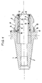
- a coupling body 1 with a coupling body which has a steep taper section 2, which is inserted into the spindle of a machine tool.
- a deformable clamping sleeve 3 is connected, which has a longitudinal bore 4 for receiving a tool.
- the clamping sleeve 3 has a conical outer surface 5, on which a clamping cylinder 6 can be rotated, which has a conical inner surface 7 parallel to the outer surface 5 of the clamping sleeve 3.
- a multi-row needle bearing 8 is provided, the needles 9 of which, as is known, are arranged obliquely to the generatrices of the conical surfaces, so that when the clamping cylinder 6 rotates in one direction, the clamping cylinder is pushed onto the clamping sleeve 3 , So in the drawing is shifted to the left, whereby the clamping sleeve 3 is pressed together and clamps the tool.
- the clamping cylinder 6 rotates in the other direction, it is shifted to the right in the drawing, whereby the clamping sleeve 3 is relieved and the tool is released.
- the clamping cylinder is rotated with the aid of a wrench which engages surfaces 10 on the clamping cylinder.
- the front end of the clamping sleeve 3 is provided with an external thread 11, onto which a stop ring 12 is screwed on a shoulder 13 abuts the front end of the clamping cylinder 6 when the clamping cylinder is not in its clamping position.
- a stop ring 12 an axial force is exerted on the clamping cylinder 6 during assembly of the chuck, which causes a weak initial clamping force between the clamping cylinder 6 and the needle bearing 8, so that when the clamping cylinder 6 is rotated, the same immediately occurs and a clamping force occurs is exerted on the clamping sleeve 3.
- the stop ring 12 also prevents the clamping cylinder from sliding off the clamping sleeve.
- the stop ring 12 is screwed on when assembling the chuck until the desired prestressing of the clamping sleeve 6 is reached, and then fixed against rotation by an adhesive. Since a slight deformation of the clamping sleeve 6 occurs as a result of the prestressing, the bore 4 is now machined exactly in the center in order to ensure that the tool inserted into the bore 4 runs smoothly.
- a releasable locking device is provided between the clamping cylinder 6 and the coupling body 1.
- the coupling body 1 is provided with a cylindrical extension 16 which engages over the rear end of the tensioning cylinder 6 and has an annular groove 17 on its inner surface, into which the locking ball 15 engages in the tensioned position of the tensioning cylinder 6.
- the locking ball 15 is primarily caused by the centrifugal force and also by a weak spring 18 brought into their locked position.
- the locking ball 15 prevents the tensioning cylinder 6 from moving axially outwards when the coupling body 1 is braked, as a result of which the clamping force would be reduced. Since no centrifugal force acts on the locking ball 15 at a standstill, the clamping cylinder 6 can simultaneously be pulled axially outwards without great effort when relieving the pressure on the clamping sleeve in order to bring the locking ball 15 out of engagement with the annular groove 17.
- a marking for example a shoulder 19, can be provided on the outer surface of the clamping sleeve 6, which is aligned with the front edge of the extension 16 in the clamping position of the clamping sleeve 6. This shows whether the locking ball 15 is engaged in the annular groove 17.
- the clamping sleeve 6 is locked in the clamping position with the aid of a lock nut 20.
- This lock nut 20 is screwed onto an external thread 21 on the coupling body 1 and interacts with the rear end of the clamping sleeve 6.
- the lock nut 20 not only clamps the clamping cylinder firmly, but it also brings about radial fixation or support of the rear end of the clamping cylinder.
- the clamping cylinder 6 can absorb the lateral forces acting on the clamping sleeve 3, which result from the cutting pressure acting on the tool, so that deflection of the clamping sleeve is avoided and perfect concentricity of the tool is ensured.
- a particularly effective radial support of the clamping cylinder end is achieved if the interacting surfaces 22 and 23 of the clamping cylinder and the lock nut 20 are, as shown, conical or hollow-conical.
Landscapes
- Engineering & Computer Science (AREA)
- Mechanical Engineering (AREA)
- Gripping On Spindles (AREA)
Abstract
Description
Die Erfindung betrifft ein Spannfutter entsprechend dem Oberbegriff des Anspruchs 1.The invention relates to a chuck according to the preamble of
Bei derartigen, auch als Rollkupplungsfutter bezeichneten und beispielsweise aus der DE-A 36 00 994 bekannten Spannfuttern wird zum Festspannen des in die Hülse eingesteckten Werkzeuges der Spannzylinder mittels eines Schraubenschlüssels gedreht und er schiebt sich aufgrund der schräg angeordneten Nadelrollen auf die konische Außenfläche der Spannhülse auf, wodurch diese zusammengedrückt wird und das Werkzeug festklemmt.In such chucks, also known as roller clutch chucks and known, for example, from DE-A 36 00 994, the clamping cylinder is rotated by means of a wrench for clamping the tool inserted into the sleeve, and it slides onto the conical outer surface of the clamping sleeve due to the obliquely arranged needle rollers , which compresses it and clamps the tool.
Der Erfindung liegt die Aufgabe zugrunde, die Wirksamkeit des Spannzylinders eines gattungsgemäßen Spannfutters verbessern.The invention has for its object to improve the effectiveness of the clamping cylinder of a generic chuck.
Erfindungsgemäß ist das vordere Ende der Spannhülse mit einem Außengewinde versehen, auf das ein Anschlagring aufschraubbar ist, der an einer Schulter am vorderen Ende des Spannzylinders anliegt und eine axiale Vorspannung auf den Spannzylinder ausübt.According to the invention, the front end of the clamping sleeve is provided with an external thread onto which a stop ring can be screwed, which rests on a shoulder at the front end of the clamping cylinder and exerts an axial prestress on the clamping cylinder.
Dadurch wird erreicht, daß beim Zusammenbau des Spannfutters der Spannzylinder durch entsprechendes Aufschrauben des Anschlagringes leicht auf die Spannhülse aufgedrückt wird, so daß nach dem Einführen des Werkzeuges in die Spannhülse ein Drehen des Spannzylinders in der einen Richtung sofort eine Axialverschiebung desselben und damit ein Zusammendrücken der Spannülse bewirkt. Der Anschlagring dient außerdem dazu, ein Abrutschen des Spannzylinders von der Spannhülse zu verhindern. Nach dem Einstellen der axialen Vorspannung wird der Anschlagring durch einen Kleber gegen Drehung gesichert.This ensures that when assembling the chuck the clamping cylinder is slightly pressed onto the clamping sleeve by screwing the stop ring accordingly, so that after inserting the tool into the clamping sleeve, rotating the clamping cylinder in one direction immediately causes an axial displacement thereof and thus a compression of the Collet causes. The stop ring also serves to prevent the clamping cylinder from slipping off the clamping sleeve. After setting the Axial preload is used to secure the stop ring against rotation using an adhesive.
Zur Freigabe des Werkzeuges wird der Spannzylinder in der anderen Richtung gedreht, wobei er sich aufgrund der Schräglage der Nadelrollen in Richtung auf das vorderen Ende der Spannhülse verschiebt, was zur Folge hat, daß sich die Spannhülse ausdehnen kann und das Werkzeug freigibt.To release the tool, the clamping cylinder is rotated in the other direction, whereby it moves due to the inclined position of the needle rollers in the direction of the front end of the clamping sleeve, with the result that the clamping sleeve can expand and the tool is released.
Um einen schnellen Werkzeugwechsel zu ermöglichen, wird die Spindel der Werkzeugmaschine abgebremst. Dieses Abbremsen bewirkt eine entsprechende Verzögerung der Dre-hung der Spannhülse, die eine Drehung des Spannzylinders relativ zu der Spannhülse und eine Axialverschiebung desselben im Sinne einer Entlastung der Hülse zur Folge haben kann. Das Werkzeug ist dann nicht mehr festgehalten und kann aus dem Spannfutter herausfallen und aufgrund der noch fortdauernden Drehung des Spannfutters beschädigt werden oder erhebliche Schäden verursachen und die Umgebung grfährden. Um dies zu vermeiden, ist erfindungsgemäß zwischen dem rückwärtigen Ende des Spannzylinders und dem Kupplungskörper eine in der Spannstellung wirksame, lösbare Arretierung vorgesehen, die verhindert, daß der Spannzylinder sich beim einem Abbremsen des Spannfutters gegenüber der Spannhülse verschieben kann.To enable a quick tool change, the spindle of the machine tool is braked. This braking causes a corresponding delay in the rotation of the clamping sleeve, which can result in a rotation of the clamping cylinder relative to the clamping sleeve and an axial displacement thereof in the sense of relieving the load on the sleeve. The tool is then no longer held and can fall out of the chuck and, due to the continued rotation of the chuck, be damaged or cause considerable damage and endanger the environment. To avoid this, according to the invention between the rear end of the clamping cylinder and the coupling body an effective, releasable locking is provided in the clamping position, which prevents the clamping cylinder from moving when the chuck is braked relative to the clamping sleeve.
Nach einem ersten Vorschlag der Erfindung kann die Arretierung einen Sperrkörper aufweisen, der verschiebbar in einer radialen, nach außen zu offenen Bohrung im Spannzylinder angeordnet ist und in der Spannstellung des Spannzylinders in eine Vertiefung einrastet, die in einem das rückwärtige Ende des Spannzylinders übergreifenden zylindrischen Fortsatz des Kupplungskörpers vorgesehen ist. Der Sperrkörper wird durch die Fliehkraft in seiner Raststellung gehalten. Zusätzlich kann in der Bohrung eine Feder vorgesehen sein, die den Sperrkörper nach außen drückt. Zum Lösen der Arretierung wird der Spannzylinder bei stillstehendem Spannfutter unter Überwindung der schwachen Federkraft axial verschoben. Der Sperrkörper ist vorzugsweise eine Kugel, und die Vertiefung kann von einer Ringnut gebildet sein, um in jeder Position des Spannzylinders ein Einrasten der Kugel sicherzustellen. Um erkennen zu können, daß der Sperrkörper eingerastet ist, kann auf der Außenfläche des Spannzylinders eine Markierung vorgesehen werden, die in der Spannstellung des Spannzylinders mit der Vorderkante des Kupplungskörpers fluchtet.According to a first proposal of the invention, the locking device can have a locking body, which is arranged displaceably in a radial, outwardly open bore in the tensioning cylinder and, in the tensioning position of the tensioning cylinder, engages in a recess which overlaps the rear end of the tensioning cylinder cylindrical extension of the coupling body is provided. The locking body is held in its locking position by centrifugal force. In addition, a spring can be provided in the bore, which presses the locking body outwards. To release the lock, the clamping cylinder is moved axially when the chuck is at a standstill and overcomes the weak spring force. The locking body is preferably a ball, and the depression can be formed by an annular groove in order to ensure that the ball engages in any position of the clamping cylinder. In order to be able to recognize that the locking body is engaged, a mark can be provided on the outer surface of the tensioning cylinder, which is aligned with the front edge of the coupling body in the tensioning position of the tensioning cylinder.
Nach einem zweiten Vorschlag der Erfiindung wird die Arretierung des Spannzylinders in seiner Spannstellung dadurch erreicht, daß das rückwärtige Ende des Spannzylinders mit einer auf ein Außengewinde am Kupplungskörper aufgeschraubten Kontermutter zusammenwirkt. Diese Ausführung hat den zuätzlichen Vorteil, daß der Spannzylinder an seinem rückwärtigen Ende radial abgestützt ist, so daß er die durch den Schnittdruck auf das Werkzeug und damit auf die Spannhülse ausgeübte Seitenkraft aufnehmen kann. Die Präzision des Spannfutters wird dadurch erheblich verbessert. Eine besonders wirksame radiale Fixierung des rückwärtigen Endes des Spannzylinders wird erreicht, wenn die zusammenwirkenden Flächen des Spannzylinders und der Kontermutter konisch bzw. hohlkegelförmig ausgebildet sind.According to a second proposal of the invention, the locking of the tensioning cylinder in its tensioning position is achieved in that the rear end of the tensioning cylinder interacts with a lock nut screwed onto an external thread on the coupling body. This design has the additional advantage that the clamping cylinder is supported radially at its rear end so that it can absorb the lateral force exerted by the cutting pressure on the tool and thus on the clamping sleeve. This significantly improves the precision of the chuck. A particularly effective radial fixation of the rear end of the clamping cylinder is achieved if the cooperating surfaces of the clamping cylinder and the lock nut are conical or hollow-conical.
Zwei Ausführungsbeispiele der Erfindung werden im folgenden unter Bezugnahme auf die Zeichnungen beschrieben. Es zeigt:
- Fig. 1
- einen Längsschnitt eines Spannfutters in einer ersten Ausführung, und
- Fig. 2
- einen Längsschnitt eines Spannfutters in einer zweiten Ausführung.
- Fig. 1
- a longitudinal section of a chuck in a first embodiment, and
- Fig. 2
- a longitudinal section of a chuck in a second embodiment.
Mit 1 ist ein Kupplungsköper bezeichnet, der einen Steilkegelabschnitt 2 aufweist, welcher in die Spindel einer Werkzeugmaschine eingesetzt wird. Mit dem Kupplungskörper 1 ist eine verformbare Spannhülse 3 verbunden, die eine Längsbohrung 4 zur Aufnahme eines Werkzeuges aufweist. Die Spannhülse 3 hat eine konische Außenfläche 5, auf der ein Spannzylinder 6 drehbar ist, der eine zur Außenfläche 5 der Spannhülse 3 parallele, konische Innenfläche 7 aufweist. Zwischen den konischen Flächen 5 und 7 ist ein mehrreihiges Nadellager 8 vorgesehen, dessen Nadeln 9, wie bekannt, schräg zu den Mantellinien der konischen Flächen angeordnet sind, so daß bei einer Drehung des Spannzylinders 6 in der einen Richtung der Spannzylinder auf die Spannhülse 3 aufgeschoben, also in der Zeichnung nach links verschoben wird, wodurch die Spannhülse 3 zusammengedrückt wird und das Werkzeug festklemmt. Bei Drehung des Spannzylinders 6 in der anderen Richtung wird dieser in der Zeichnung nach rechts verschoben, wodurch die Spannhülse 3 entlastet wird und das Werkzeug freigibt. Das Drehen des Spannzylinders erfolgt mit Hilfe eines Schraubenschlüssels, der an Flächen 10 am Spannzylinder angreift.1 with a coupling body is designated, which has a
Das vordere Ende der Spannhülse 3 ist mit einem Außengewinde 11 versehen, auf das ein Anschlagring 12 aufgeschraubt ist, der an einer Schulter 13 am vorderen Ende des Spannzylinders 6 anliegt, wenn der Spannzylinder nicht in seiner Spannstellung ist. Mit diesem Anschlagring 12 wird beim Zusammenbau des Spannfutters auf den Spannzylinder 6 eine axiale Kraft ausgeübt, die eine schwache Anfangs-Klemmkraft zwischen dem Spannzylinder 6 und dem Nadellager 8 bewirkt, so daß beim Drehen des Spannzylinders 6 sofort eine axiale Verschiebung desselben eintritt und eine Klemmkraft auf die Spannhülse 3 ausgeübt wird. Der Anschlagring 12 verhindert außerdem ein Abgleiten des Spannzylinders von der Spannhülse. Der Anschlagring 12 wird beim Zusammenbau des Spannfutters so weit aufgeschraubt, bis die gewünschte Vorspannung der Spannhülse 6 erreicht ist, und dann durch einen Kleber gegen Drehung fixiert. Da durch die Vorspannung eine geringfügige Verformung der Spannhülse 6 eintritt, wird die Bohrung 4 nun genau zentrisch bearbeitet, um einen einwandfreien Rundlauf des in die Borhung 4 eingesetzten Werkzeuges sicherzustellen.The front end of the
Um ein ungewolltes Entspannen der Spannhülse 3 beim Abbremsen des Spannfutters zu verhindern, ist zwischen dem Spannzylinder 6 und dem Kupplungskörper 1 eine lösbare Arretierung vorgesehen. Zu diesem Zweck ist nahe seines rückwärtigen Endes im Spannzylinder 6 eine radiale, nach außen zu offene Bohrung 14 vorgesehen, in der eine Sperrkugel 15 verschiebbar, jedoch gegen Herausfallen gesichert, angeordnet ist. Der Kupplungskörper 1 ist mit einem zylindrischen Fortsatz 16 versehen, der das rückwärtige Ende des Spannzylinders 6 übergreift und an seiner Innenfläche eine Ringnut 17 aufweist, in welche die Sperrkugel 15 in der Spannstellung des Spannzylinders 6 eingreift. Die Sperrkugel 15 wird in erster Linie durch die Fliehkraft und zusätzlich durch eine schwache Feder 18 in ihre Sperrstellung gebracht. Die Sperrkugel 15 verhindert, daß sich der Spannzylinder 6 beim Abbremsen des Kupplungskörpers 1 axial nach außen verschieben kann, wodurch die Klemmkraft verringert würde. Da im Stillstand keine Fliehkraft auf die Sperrkugel 15 wirkt, kann der Spannzylinder 6 beim Drehen zur Entlastung der Spannhülse ohne große Kraftanstrengung gleichzeitig axial nach außen gezogen werden, um die Sperrkugel 15 außer Eingriff mit der Ringnut 17 zu bringen. An der Außenfläche der Spannhülse 6 kann eine Markierung, z.B. ein Absatz 19, vorgesehen sein, der in der Spannstellung der Spannhülse 6 mit der Vorderkante des Fortsatzes 16 fluchtet. Dadurch ist erkennbar, ob die Sperrkugel 15 in die Ringnut 17 eingerastet ist.In order to prevent unwanted relaxation of the
Bei dem Ausführungsbeispiel gemäß Fig. 2 erfolgt die lösbare Arretierung der Spannhülse 6 in der Spannstellung mit Hilfe einer Kontermutter 20. Diese Kontermutter 20 ist auf ein Außengewinde 21 am Kupplungskörper 1 aufgeschraubt und wirkt mit dem rückwärtigen Ende der Spannhülse 6 zusammen. Die Kontermutter 20 klemmt den Spannzylinder nicht nur fest, sondern sie bewirkt auch eine radiale Fixierung oder Abstützung des rückwärtigen Endes des Spannzylinders. Dadurch kann der Spannzylinder 6 die auf die Spannhülse 3 wirkenden Seitenkräfte, die von dem auf das Werkzeug wirkenden Schnittdruck herrühren, aufnehmen, so daß eine Durchbiegung der Spannhülse vermieden und ein einwandfreier Rundlauf des Werkzeuges sichergestellt ist. Eine besonders wirksame radiale Abstützung des Spannzylinderendes wird erreicht, wenn die miteinander zusammenwirkenden Flächen 22 und 23 des Spannzylinders und der Kontermutter 20, wie dargestellt, konisch bzw. hohlkegelförmig sind.In the exemplary embodiment according to FIG. 2, the clamping sleeve 6 is locked in the clamping position with the aid of a
Claims (9)
Applications Claiming Priority (2)
| Application Number | Priority Date | Filing Date | Title |
|---|---|---|---|
| DE4209175 | 1992-03-20 | ||
| DE4209175A DE4209175A1 (en) | 1992-03-20 | 1992-03-20 | CHUCK |
Publications (2)
| Publication Number | Publication Date |
|---|---|
| EP0561395A1 true EP0561395A1 (en) | 1993-09-22 |
| EP0561395B1 EP0561395B1 (en) | 1995-10-04 |
Family
ID=6454658
Family Applications (1)
| Application Number | Title | Priority Date | Filing Date |
|---|---|---|---|
| EP93104406A Expired - Lifetime EP0561395B1 (en) | 1992-03-20 | 1993-03-18 | Chuck |
Country Status (2)
| Country | Link |
|---|---|
| EP (1) | EP0561395B1 (en) |
| DE (2) | DE4209175A1 (en) |
Cited By (4)
| Publication number | Priority date | Publication date | Assignee | Title |
|---|---|---|---|---|
| WO1997013604A1 (en) * | 1995-10-09 | 1997-04-17 | Erkki Kalevi Rinne | Procedure for fastening an object and a hydraulic fastening apparatus |
| EP0841120A1 (en) * | 1996-11-12 | 1998-05-13 | Kabushiki Kaisha Kosmek | Clamping device |
| EP0904876A3 (en) * | 1997-09-26 | 1999-04-07 | Daishowa Seiki Co., Ltd. | Chuck |
| WO2005084858A1 (en) * | 2004-03-05 | 2005-09-15 | Index-Werke Gmbh & Co. Kg Hahn & Tessky | Clamping head |
Citations (3)
| Publication number | Priority date | Publication date | Assignee | Title |
|---|---|---|---|---|
| DE3517246A1 (en) * | 1984-06-29 | 1986-01-09 | Daishowa Seiki Co., Ltd., Higashiosaka, Osaka | CHUCK FOR A MACHINE TOOL |
| US4721423A (en) * | 1986-10-07 | 1988-01-26 | Daishowa Seiki Kabushiki Kaisha | Chuck |
| AT385224B (en) * | 1985-03-14 | 1988-03-10 | Glasformen Und Maschinen Ges M | Chuck for clamping rotating tools, such as drills, milling cutters or the like, in machine tools |
-
1992
- 1992-03-20 DE DE4209175A patent/DE4209175A1/en not_active Withdrawn
-
1993
- 1993-03-18 DE DE59300699T patent/DE59300699D1/en not_active Expired - Fee Related
- 1993-03-18 EP EP93104406A patent/EP0561395B1/en not_active Expired - Lifetime
Patent Citations (3)
| Publication number | Priority date | Publication date | Assignee | Title |
|---|---|---|---|---|
| DE3517246A1 (en) * | 1984-06-29 | 1986-01-09 | Daishowa Seiki Co., Ltd., Higashiosaka, Osaka | CHUCK FOR A MACHINE TOOL |
| AT385224B (en) * | 1985-03-14 | 1988-03-10 | Glasformen Und Maschinen Ges M | Chuck for clamping rotating tools, such as drills, milling cutters or the like, in machine tools |
| US4721423A (en) * | 1986-10-07 | 1988-01-26 | Daishowa Seiki Kabushiki Kaisha | Chuck |
Non-Patent Citations (1)
| Title |
|---|
| PATENT ABSTRACTS OF JAPAN vol. 7, no. 12 (M-186)(1157) 19. Januar 1983 & JP-A-57 168 805 ( SEIWA ) 18. Oktober 1982 * |
Cited By (6)
| Publication number | Priority date | Publication date | Assignee | Title |
|---|---|---|---|---|
| WO1997013604A1 (en) * | 1995-10-09 | 1997-04-17 | Erkki Kalevi Rinne | Procedure for fastening an object and a hydraulic fastening apparatus |
| US5979911A (en) * | 1995-10-09 | 1999-11-09 | Rinne; Erkki K. | Procedure for fastening an object and a hydraulic fastening apparatus |
| EP0841120A1 (en) * | 1996-11-12 | 1998-05-13 | Kabushiki Kaisha Kosmek | Clamping device |
| US5979267A (en) * | 1996-11-12 | 1999-11-09 | Kabushiki Kaisha Kosmek | Clamping device |
| EP0904876A3 (en) * | 1997-09-26 | 1999-04-07 | Daishowa Seiki Co., Ltd. | Chuck |
| WO2005084858A1 (en) * | 2004-03-05 | 2005-09-15 | Index-Werke Gmbh & Co. Kg Hahn & Tessky | Clamping head |
Also Published As
| Publication number | Publication date |
|---|---|
| DE59300699D1 (en) | 1995-11-09 |
| DE4209175A1 (en) | 1993-09-23 |
| EP0561395B1 (en) | 1995-10-04 |
Similar Documents
| Publication | Publication Date | Title |
|---|---|---|
| EP2792439B1 (en) | Quick change system for a tool holder | |
| DE3734052A1 (en) | QUICK-CHANGE CLAMPING DEVICE FOR MACHINE TOOLS | |
| DE2621932B2 (en) | Chuck for clamping head and stud bolts during the screwing-in process | |
| DE3048274A1 (en) | DRILL CHUCK | |
| DE2227309A1 (en) | INTERMEDIATE FOR TOOL HOLDER | |
| EP0131069B1 (en) | Rolling tool | |
| DE2620050C2 (en) | ||
| AT393302B (en) | DEVICE FOR CONNECTING TWO TOOL PARTS | |
| AT396887B (en) | DEVICE FOR CONNECTING TWO MACHINE PARTS, IN PARTICULAR TWO TOOL PARTS OF MACHINE TOOLS | |
| EP1663555B1 (en) | Clamping device | |
| DE4134405A1 (en) | DEVICE FOR ATTACHING A CUTTING TOOL TO A CUTTING MACHINE | |
| DE19703354C1 (en) | Clamping device for two separable machine parts | |
| DE1919439C3 (en) | Quick-release chuck for tools with a shaft | |
| DE69215905T2 (en) | TENSIONER FOR MILLING OR SIMILAR, ADAPTABLE FOR DIFFERENT HOLDER SIZES | |
| EP0561395B1 (en) | Chuck | |
| DE602004007213T2 (en) | chuck | |
| DE19727099A1 (en) | Locking bolt for holding two components together, e.g. for holding jigs in place during welding | |
| DE4209485C2 (en) | ||
| DE1948452A1 (en) | Jig | |
| EP4155015A1 (en) | Device and coupling element for a clamping device | |
| DE4231959A1 (en) | Clamping system for hollow taper shank tools in machine tool spindle - has V-section clamping segments pivoted in track behind drawbar head and expanded outwards by movement of drawbar to abut against internal shoulder of shank | |
| DE9104377U1 (en) | Chuck for shafts | |
| DE19526755A1 (en) | Clamp mounting for rotating body esp. grinding disc | |
| DE3839663C2 (en) | ||
| DE4222703C2 (en) | Tool clamping device |
Legal Events
| Date | Code | Title | Description |
|---|---|---|---|
| PUAI | Public reference made under article 153(3) epc to a published international application that has entered the european phase |
Free format text: ORIGINAL CODE: 0009012 |
|
| AK | Designated contracting states |
Kind code of ref document: A1 Designated state(s): BE CH DE FR GB LI LU NL |
|
| 17P | Request for examination filed |
Effective date: 19931227 |
|
| 17Q | First examination report despatched |
Effective date: 19950321 |
|
| GRAA | (expected) grant |
Free format text: ORIGINAL CODE: 0009210 |
|
| AK | Designated contracting states |
Kind code of ref document: B1 Designated state(s): BE CH DE FR GB LI LU NL |
|
| PG25 | Lapsed in a contracting state [announced via postgrant information from national office to epo] |
Ref country code: NL Free format text: LAPSE BECAUSE OF FAILURE TO SUBMIT A TRANSLATION OF THE DESCRIPTION OR TO PAY THE FEE WITHIN THE PRESCRIBED TIME-LIMIT Effective date: 19951004 Ref country code: GB Effective date: 19951004 Ref country code: BE Effective date: 19951004 |
|
| REF | Corresponds to: |
Ref document number: 59300699 Country of ref document: DE Date of ref document: 19951109 |
|
| ET | Fr: translation filed | ||
| NLV1 | Nl: lapsed or annulled due to failure to fulfill the requirements of art. 29p and 29m of the patents act | ||
| PG25 | Lapsed in a contracting state [announced via postgrant information from national office to epo] |
Ref country code: LU Free format text: LAPSE BECAUSE OF NON-PAYMENT OF DUE FEES Effective date: 19960331 Ref country code: LI Effective date: 19960331 Ref country code: CH Effective date: 19960331 |
|
| GBV | Gb: ep patent (uk) treated as always having been void in accordance with gb section 77(7)/1977 [no translation filed] |
Effective date: 19951004 |
|
| PLBE | No opposition filed within time limit |
Free format text: ORIGINAL CODE: 0009261 |
|
| 26N | No opposition filed | ||
| REG | Reference to a national code |
Ref country code: CH Ref legal event code: PL |
|
| PGFP | Annual fee paid to national office [announced via postgrant information from national office to epo] |
Ref country code: FR Payment date: 19980323 Year of fee payment: 6 |
|
| PGFP | Annual fee paid to national office [announced via postgrant information from national office to epo] |
Ref country code: DE Payment date: 19990531 Year of fee payment: 7 |
|
| PG25 | Lapsed in a contracting state [announced via postgrant information from national office to epo] |
Ref country code: FR Free format text: LAPSE BECAUSE OF NON-PAYMENT OF DUE FEES Effective date: 19991130 |
|
| REG | Reference to a national code |
Ref country code: FR Ref legal event code: ST |
|
| PG25 | Lapsed in a contracting state [announced via postgrant information from national office to epo] |
Ref country code: DE Free format text: LAPSE BECAUSE OF NON-PAYMENT OF DUE FEES Effective date: 20010103 |