EP0561395A1 - Mandrin - Google Patents
Mandrin Download PDFInfo
- Publication number
- EP0561395A1 EP0561395A1 EP93104406A EP93104406A EP0561395A1 EP 0561395 A1 EP0561395 A1 EP 0561395A1 EP 93104406 A EP93104406 A EP 93104406A EP 93104406 A EP93104406 A EP 93104406A EP 0561395 A1 EP0561395 A1 EP 0561395A1
- Authority
- EP
- European Patent Office
- Prior art keywords
- clamping
- clamping cylinder
- cylinder
- chuck according
- sleeve
- Prior art date
- Legal status (The legal status is an assumption and is not a legal conclusion. Google has not performed a legal analysis and makes no representation as to the accuracy of the status listed.)
- Granted
Links
Images

Classifications
-
- B—PERFORMING OPERATIONS; TRANSPORTING
- B23—MACHINE TOOLS; METAL-WORKING NOT OTHERWISE PROVIDED FOR
- B23B—TURNING; BORING
- B23B31/00—Chucks; Expansion mandrels; Adaptations thereof for remote control
- B23B31/02—Chucks
- B23B31/10—Chucks characterised by the retaining or gripping devices or their immediate operating means
- B23B31/117—Retention by friction only, e.g. using springs, resilient sleeves, tapers
Definitions
- the invention relates to a chuck according to the preamble of claim 1.
- the clamping cylinder is rotated by means of a wrench for clamping the tool inserted into the sleeve, and it slides onto the conical outer surface of the clamping sleeve due to the obliquely arranged needle rollers , which compresses it and clamps the tool.
- the invention has for its object to improve the effectiveness of the clamping cylinder of a generic chuck.
- the front end of the clamping sleeve is provided with an external thread onto which a stop ring can be screwed, which rests on a shoulder at the front end of the clamping cylinder and exerts an axial prestress on the clamping cylinder.
- the stop ring also serves to prevent the clamping cylinder from slipping off the clamping sleeve. After setting the Axial preload is used to secure the stop ring against rotation using an adhesive.
- the clamping cylinder is rotated in the other direction, whereby it moves due to the inclined position of the needle rollers in the direction of the front end of the clamping sleeve, with the result that the clamping sleeve can expand and the tool is released.
- the spindle of the machine tool is braked.
- This braking causes a corresponding delay in the rotation of the clamping sleeve, which can result in a rotation of the clamping cylinder relative to the clamping sleeve and an axial displacement thereof in the sense of relieving the load on the sleeve.
- the tool is then no longer held and can fall out of the chuck and, due to the continued rotation of the chuck, be damaged or cause considerable damage and endanger the environment.
- an effective, releasable locking is provided in the clamping position, which prevents the clamping cylinder from moving when the chuck is braked relative to the clamping sleeve.
- the locking device can have a locking body, which is arranged displaceably in a radial, outwardly open bore in the tensioning cylinder and, in the tensioning position of the tensioning cylinder, engages in a recess which overlaps the rear end of the tensioning cylinder cylindrical extension of the coupling body is provided.
- the locking body is held in its locking position by centrifugal force.
- a spring can be provided in the bore, which presses the locking body outwards. To release the lock, the clamping cylinder is moved axially when the chuck is at a standstill and overcomes the weak spring force.
- the locking body is preferably a ball, and the depression can be formed by an annular groove in order to ensure that the ball engages in any position of the clamping cylinder.
- a mark can be provided on the outer surface of the tensioning cylinder, which is aligned with the front edge of the coupling body in the tensioning position of the tensioning cylinder.
- the locking of the tensioning cylinder in its tensioning position is achieved in that the rear end of the tensioning cylinder interacts with a lock nut screwed onto an external thread on the coupling body.
- This design has the additional advantage that the clamping cylinder is supported radially at its rear end so that it can absorb the lateral force exerted by the cutting pressure on the tool and thus on the clamping sleeve. This significantly improves the precision of the chuck.
- a particularly effective radial fixation of the rear end of the clamping cylinder is achieved if the cooperating surfaces of the clamping cylinder and the lock nut are conical or hollow-conical.
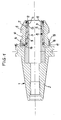
- a coupling body 1 with a coupling body which has a steep taper section 2, which is inserted into the spindle of a machine tool.
- a deformable clamping sleeve 3 is connected, which has a longitudinal bore 4 for receiving a tool.
- the clamping sleeve 3 has a conical outer surface 5, on which a clamping cylinder 6 can be rotated, which has a conical inner surface 7 parallel to the outer surface 5 of the clamping sleeve 3.
- a multi-row needle bearing 8 is provided, the needles 9 of which, as is known, are arranged obliquely to the generatrices of the conical surfaces, so that when the clamping cylinder 6 rotates in one direction, the clamping cylinder is pushed onto the clamping sleeve 3 , So in the drawing is shifted to the left, whereby the clamping sleeve 3 is pressed together and clamps the tool.
- the clamping cylinder 6 rotates in the other direction, it is shifted to the right in the drawing, whereby the clamping sleeve 3 is relieved and the tool is released.
- the clamping cylinder is rotated with the aid of a wrench which engages surfaces 10 on the clamping cylinder.
- the front end of the clamping sleeve 3 is provided with an external thread 11, onto which a stop ring 12 is screwed on a shoulder 13 abuts the front end of the clamping cylinder 6 when the clamping cylinder is not in its clamping position.
- a stop ring 12 an axial force is exerted on the clamping cylinder 6 during assembly of the chuck, which causes a weak initial clamping force between the clamping cylinder 6 and the needle bearing 8, so that when the clamping cylinder 6 is rotated, the same immediately occurs and a clamping force occurs is exerted on the clamping sleeve 3.
- the stop ring 12 also prevents the clamping cylinder from sliding off the clamping sleeve.
- the stop ring 12 is screwed on when assembling the chuck until the desired prestressing of the clamping sleeve 6 is reached, and then fixed against rotation by an adhesive. Since a slight deformation of the clamping sleeve 6 occurs as a result of the prestressing, the bore 4 is now machined exactly in the center in order to ensure that the tool inserted into the bore 4 runs smoothly.
- a releasable locking device is provided between the clamping cylinder 6 and the coupling body 1.
- the coupling body 1 is provided with a cylindrical extension 16 which engages over the rear end of the tensioning cylinder 6 and has an annular groove 17 on its inner surface, into which the locking ball 15 engages in the tensioned position of the tensioning cylinder 6.
- the locking ball 15 is primarily caused by the centrifugal force and also by a weak spring 18 brought into their locked position.
- the locking ball 15 prevents the tensioning cylinder 6 from moving axially outwards when the coupling body 1 is braked, as a result of which the clamping force would be reduced. Since no centrifugal force acts on the locking ball 15 at a standstill, the clamping cylinder 6 can simultaneously be pulled axially outwards without great effort when relieving the pressure on the clamping sleeve in order to bring the locking ball 15 out of engagement with the annular groove 17.
- a marking for example a shoulder 19, can be provided on the outer surface of the clamping sleeve 6, which is aligned with the front edge of the extension 16 in the clamping position of the clamping sleeve 6. This shows whether the locking ball 15 is engaged in the annular groove 17.
- the clamping sleeve 6 is locked in the clamping position with the aid of a lock nut 20.
- This lock nut 20 is screwed onto an external thread 21 on the coupling body 1 and interacts with the rear end of the clamping sleeve 6.
- the lock nut 20 not only clamps the clamping cylinder firmly, but it also brings about radial fixation or support of the rear end of the clamping cylinder.
- the clamping cylinder 6 can absorb the lateral forces acting on the clamping sleeve 3, which result from the cutting pressure acting on the tool, so that deflection of the clamping sleeve is avoided and perfect concentricity of the tool is ensured.
- a particularly effective radial support of the clamping cylinder end is achieved if the interacting surfaces 22 and 23 of the clamping cylinder and the lock nut 20 are, as shown, conical or hollow-conical.
Landscapes
- Engineering & Computer Science (AREA)
- Mechanical Engineering (AREA)
- Gripping On Spindles (AREA)
Applications Claiming Priority (2)
| Application Number | Priority Date | Filing Date | Title |
|---|---|---|---|
| DE4209175 | 1992-03-20 | ||
| DE4209175A DE4209175A1 (de) | 1992-03-20 | 1992-03-20 | Spannfutter |
Publications (2)
| Publication Number | Publication Date |
|---|---|
| EP0561395A1 true EP0561395A1 (fr) | 1993-09-22 |
| EP0561395B1 EP0561395B1 (fr) | 1995-10-04 |
Family
ID=6454658
Family Applications (1)
| Application Number | Title | Priority Date | Filing Date |
|---|---|---|---|
| EP93104406A Expired - Lifetime EP0561395B1 (fr) | 1992-03-20 | 1993-03-18 | Mandrin |
Country Status (2)
| Country | Link |
|---|---|
| EP (1) | EP0561395B1 (fr) |
| DE (2) | DE4209175A1 (fr) |
Cited By (4)
| Publication number | Priority date | Publication date | Assignee | Title |
|---|---|---|---|---|
| WO1997013604A1 (fr) * | 1995-10-09 | 1997-04-17 | Erkki Kalevi Rinne | Procede de fixation d'un objet et appareil de fixation hydraulique |
| EP0841120A1 (fr) * | 1996-11-12 | 1998-05-13 | Kabushiki Kaisha Kosmek | Dispositif de serrage |
| EP0904876A3 (fr) * | 1997-09-26 | 1999-04-07 | Daishowa Seiki Co., Ltd. | Mandrin |
| WO2005084858A1 (fr) * | 2004-03-05 | 2005-09-15 | Index-Werke Gmbh & Co. Kg Hahn & Tessky | Tete a serrage |
Citations (3)
| Publication number | Priority date | Publication date | Assignee | Title |
|---|---|---|---|---|
| DE3517246A1 (de) * | 1984-06-29 | 1986-01-09 | Daishowa Seiki Co., Ltd., Higashiosaka, Osaka | Spannfutter fuer eine werkzeugmaschine |
| US4721423A (en) * | 1986-10-07 | 1988-01-26 | Daishowa Seiki Kabushiki Kaisha | Chuck |
| AT385224B (de) * | 1985-03-14 | 1988-03-10 | Glasformen Und Maschinen Ges M | Spannfutter zur einspannung rotierender werkzeuge wie bohrer, fraeser oder dgl. in werkzeugmaschinen |
-
1992
- 1992-03-20 DE DE4209175A patent/DE4209175A1/de not_active Withdrawn
-
1993
- 1993-03-18 DE DE59300699T patent/DE59300699D1/de not_active Expired - Fee Related
- 1993-03-18 EP EP93104406A patent/EP0561395B1/fr not_active Expired - Lifetime
Patent Citations (3)
| Publication number | Priority date | Publication date | Assignee | Title |
|---|---|---|---|---|
| DE3517246A1 (de) * | 1984-06-29 | 1986-01-09 | Daishowa Seiki Co., Ltd., Higashiosaka, Osaka | Spannfutter fuer eine werkzeugmaschine |
| AT385224B (de) * | 1985-03-14 | 1988-03-10 | Glasformen Und Maschinen Ges M | Spannfutter zur einspannung rotierender werkzeuge wie bohrer, fraeser oder dgl. in werkzeugmaschinen |
| US4721423A (en) * | 1986-10-07 | 1988-01-26 | Daishowa Seiki Kabushiki Kaisha | Chuck |
Non-Patent Citations (1)
| Title |
|---|
| PATENT ABSTRACTS OF JAPAN vol. 7, no. 12 (M-186)(1157) 19. Januar 1983 & JP-A-57 168 805 ( SEIWA ) 18. Oktober 1982 * |
Cited By (6)
| Publication number | Priority date | Publication date | Assignee | Title |
|---|---|---|---|---|
| WO1997013604A1 (fr) * | 1995-10-09 | 1997-04-17 | Erkki Kalevi Rinne | Procede de fixation d'un objet et appareil de fixation hydraulique |
| US5979911A (en) * | 1995-10-09 | 1999-11-09 | Rinne; Erkki K. | Procedure for fastening an object and a hydraulic fastening apparatus |
| EP0841120A1 (fr) * | 1996-11-12 | 1998-05-13 | Kabushiki Kaisha Kosmek | Dispositif de serrage |
| US5979267A (en) * | 1996-11-12 | 1999-11-09 | Kabushiki Kaisha Kosmek | Clamping device |
| EP0904876A3 (fr) * | 1997-09-26 | 1999-04-07 | Daishowa Seiki Co., Ltd. | Mandrin |
| WO2005084858A1 (fr) * | 2004-03-05 | 2005-09-15 | Index-Werke Gmbh & Co. Kg Hahn & Tessky | Tete a serrage |
Also Published As
| Publication number | Publication date |
|---|---|
| DE59300699D1 (de) | 1995-11-09 |
| DE4209175A1 (de) | 1993-09-23 |
| EP0561395B1 (fr) | 1995-10-04 |
Similar Documents
| Publication | Publication Date | Title |
|---|---|---|
| EP2792439B1 (fr) | Système de changement rapide pour un porte-outil | |
| DE3734052A1 (de) | Schnellwechsel-einspannvorrichtung fuer werkzeugmaschinen | |
| DE2621932B2 (de) | Futter zum Spannen von Kopf- und Stiftschrauben beim Einschraubvorgang | |
| DE3048274A1 (de) | Bohrfutter | |
| DE2227309A1 (de) | Zwischenstueck fuer werkzeughalter | |
| EP0131069B1 (fr) | Outil de laminage | |
| DE2620050C2 (fr) | ||
| AT393302B (de) | Vorrichtung zur verbindung zweier werkzeugteile | |
| AT396887B (de) | Vorrichtung zur verbindung zweier maschinenteile, insbesondere zweier werkzeugteile von werkzeugmaschinen | |
| EP1663555B1 (fr) | Dispositif de serrage | |
| DE4134405A1 (de) | Vorrichtung zum befestigen eines schneidwerkzeugs an einer schneidmaschine | |
| DE19703354C1 (de) | Spannvorrichtung zum Spannen zweier voneinander lösbarer Maschinenteile, insbesondere zum Festspannen eines Werkzeuges oder Werkstückes an einer Bearbeitungsmaschine | |
| DE1919439C3 (de) | Schnellspannfutter für einen Schaft aufweisende Werkzeuge | |
| DE69215905T2 (de) | Spannvorrichtung für fräser oder ähnliche, anpassbar für verschiedene haltergrössen | |
| EP0561395B1 (fr) | Mandrin | |
| DE602004007213T2 (de) | Spannfutter | |
| DE19727099A1 (de) | Spannbolzen | |
| DE4209485C2 (fr) | ||
| DE1948452A1 (de) | Spannvorrichtung | |
| EP4155015A1 (fr) | Dispositif de serrage pour un outil ou une pièce à usiner doté d'une pince de serrage et d'un élément de serrage pour un dispositif de serrage et procédé de serrage d'un dispositif de serrage ou de serrage | |
| DE4231959A1 (de) | Werkzeugspann- und -lösevorrichtung für eine Werkzeugmaschine | |
| DE9104377U1 (de) | Spannfutter für Schäfte | |
| DE19526755A1 (de) | Spannvorrichtung | |
| DE3839663C2 (fr) | ||
| DE4222703C2 (de) | Spannvorrichtung für Werkzeuge |
Legal Events
| Date | Code | Title | Description |
|---|---|---|---|
| PUAI | Public reference made under article 153(3) epc to a published international application that has entered the european phase |
Free format text: ORIGINAL CODE: 0009012 |
|
| AK | Designated contracting states |
Kind code of ref document: A1 Designated state(s): BE CH DE FR GB LI LU NL |
|
| 17P | Request for examination filed |
Effective date: 19931227 |
|
| 17Q | First examination report despatched |
Effective date: 19950321 |
|
| GRAA | (expected) grant |
Free format text: ORIGINAL CODE: 0009210 |
|
| AK | Designated contracting states |
Kind code of ref document: B1 Designated state(s): BE CH DE FR GB LI LU NL |
|
| PG25 | Lapsed in a contracting state [announced via postgrant information from national office to epo] |
Ref country code: NL Free format text: LAPSE BECAUSE OF FAILURE TO SUBMIT A TRANSLATION OF THE DESCRIPTION OR TO PAY THE FEE WITHIN THE PRESCRIBED TIME-LIMIT Effective date: 19951004 Ref country code: GB Effective date: 19951004 Ref country code: BE Effective date: 19951004 |
|
| REF | Corresponds to: |
Ref document number: 59300699 Country of ref document: DE Date of ref document: 19951109 |
|
| ET | Fr: translation filed | ||
| NLV1 | Nl: lapsed or annulled due to failure to fulfill the requirements of art. 29p and 29m of the patents act | ||
| PG25 | Lapsed in a contracting state [announced via postgrant information from national office to epo] |
Ref country code: LU Free format text: LAPSE BECAUSE OF NON-PAYMENT OF DUE FEES Effective date: 19960331 Ref country code: LI Effective date: 19960331 Ref country code: CH Effective date: 19960331 |
|
| GBV | Gb: ep patent (uk) treated as always having been void in accordance with gb section 77(7)/1977 [no translation filed] |
Effective date: 19951004 |
|
| PLBE | No opposition filed within time limit |
Free format text: ORIGINAL CODE: 0009261 |
|
| 26N | No opposition filed | ||
| REG | Reference to a national code |
Ref country code: CH Ref legal event code: PL |
|
| PGFP | Annual fee paid to national office [announced via postgrant information from national office to epo] |
Ref country code: FR Payment date: 19980323 Year of fee payment: 6 |
|
| PGFP | Annual fee paid to national office [announced via postgrant information from national office to epo] |
Ref country code: DE Payment date: 19990531 Year of fee payment: 7 |
|
| PG25 | Lapsed in a contracting state [announced via postgrant information from national office to epo] |
Ref country code: FR Free format text: LAPSE BECAUSE OF NON-PAYMENT OF DUE FEES Effective date: 19991130 |
|
| REG | Reference to a national code |
Ref country code: FR Ref legal event code: ST |
|
| PG25 | Lapsed in a contracting state [announced via postgrant information from national office to epo] |
Ref country code: DE Free format text: LAPSE BECAUSE OF NON-PAYMENT OF DUE FEES Effective date: 20010103 |