EP0839665B1 - Bandkassette mit Mitteln zum Arretieren des Bandendes - Google Patents
Bandkassette mit Mitteln zum Arretieren des Bandendes Download PDFInfo
- Publication number
- EP0839665B1 EP0839665B1 EP19960117526 EP96117526A EP0839665B1 EP 0839665 B1 EP0839665 B1 EP 0839665B1 EP 19960117526 EP19960117526 EP 19960117526 EP 96117526 A EP96117526 A EP 96117526A EP 0839665 B1 EP0839665 B1 EP 0839665B1
- Authority
- EP
- European Patent Office
- Prior art keywords
- tape
- cassette
- hook
- cleat
- case
- Prior art date
- Legal status (The legal status is an assumption and is not a legal conclusion. Google has not performed a legal analysis and makes no representation as to the accuracy of the status listed.)
- Expired - Lifetime
Links
Images


Classifications
-
- B—PERFORMING OPERATIONS; TRANSPORTING
- B41—PRINTING; LINING MACHINES; TYPEWRITERS; STAMPS
- B41J—TYPEWRITERS; SELECTIVE PRINTING MECHANISMS, i.e. MECHANISMS PRINTING OTHERWISE THAN FROM A FORME; CORRECTION OF TYPOGRAPHICAL ERRORS
- B41J29/00—Details of, or accessories for, typewriters or selective printing mechanisms not otherwise provided for
- B41J29/46—Applications of alarms, e.g. responsive to approach of end of line
- B41J29/48—Applications of alarms, e.g. responsive to approach of end of line responsive to breakage or exhaustion of paper or approach of bottom of paper
Definitions
- the invention relates to a cassette according to the preamble of claim 1.
- a cartridge contains a supply of the ribbon to be printed and a supply of an ink ribbon.
- the ribbon to be printed and the ribbon are on top of each other passed through a printing area of the tape printing device.
- a tape printer that works with a cartridge of this type e.g. in EP-A-0487313.
- Printing equipment is essentially the structure of the tape to be printed equal; i.e. it includes an upper one, with a picture layer to be printed on using an adhesive layer a peelable backing layer is attached.
- a cassette contains one Supply of ribbon to be printed, supply of ribbon and a supply of self-adhesive backing tape.
- the back band has an adhesive layer that is in contact with the image receiving layer is to bring a substrate layer and a second adhesive layer with a peelable backing layer is covered.
- the letters appear as a reflection the transparent image-receiving layer is printed on.
- the supply wrap is used up, ie. printed, the tape is completely out during printing pulled out of the cassette.
- the pressure roller then comes in direct Touch with the ribbon, so that a high tensile strength the ribbon acts and it also completely from his Winding core is unwound. Since the ribbon is generally with an adhesive tape section is attached to the winding core this section of tape is now in contact with the platen roller and sticks to it The ribbon is now on the platen wound up until the printing system is completely blocked.
- the present invention is based on the prior art the problem underlying a cassette with a supply reel with tape to be printed on, with a complete run out of the tape is not to be feared, though no fixation of the tape to an unwinder or an additional one Adhesive coating of the tape end is necessary.
- the problem is solved by the teaching of the claim 1 solved. It is suggested from the supply wrap of the tape to provide separate means for locking the strap end on the housing, that grasp and lock the end of the tape.
- the advantages of the invention consist primarily in the cost savings for the role of Supply wrap without running the risk of the printing mechanism - as described above - blocked, and in that by the Omission of the roll an automatic production of the cassette is facilitated.
- the means for locking the end portion of the band include preferably a hook with a complementary opening, which is usually near the end of the tape in the tape is introduced, cooperates.
- the hook thus detects the opening at the end of the band and fixes the band.
- Such means for pretensioning the band can, for example one with respect to the direction of transport of the tape downstream of the Include hook arranged web on which the tape with his the surface opposite the hook.
- the jetty is now so arranged that the tape in the area between the hook and the web takes a curved course. Because of the stiffness of the band material, however, this always strives to be one take as straight a course as possible.
- the web can be on an upper or lower wall the housing of the cassette and also (in the Rule convex). It should be noted that the web in the Principle can be as short as long as it is the desired curved The course of the tape causes.
- the surface of the band facing the hook downstream of the web a surface connected to the housing of the cassette, in particular on a wall of the housing.
- the course of the Band is then defined by three points, which are used to manufacture positioned according to the pressure of the tape on the hook become. Two points, the hook and the downstream of the Ridges connected to the housing are in contact a first surface of the tape, e.g. the back surface can be.
- the bridge is on the opposite surface.
- the housing-related Surface of an outer wall of the cassette can be what a enables simple and inexpensive implementation. Alternatively can also, for example, a separate web or an outlet of the Housing for the tape as related to the housing Serve area.
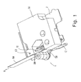
- FIG. 1 shows a perspective view of a cassette receiving space a tape printing device.
- the cassette recording room includes a thermal print head 10 and a platen 4 which cooperate and a pressure zone in a manner known per se define.
- the printhead 10 is pivotable on one mounted a pivot point printhead support 12 so that it can be brought into contact with the pressure roller 4 and from it can be moved to remove a cassette and to be able to replace.
- This can be coupled with a lid of the cassette receiving space, e.g. from EP-A-0487313 has become known. Then with the lid open the print head 10 spaced from the platen 4 so that the Cassette 56 can be easily removed or inserted.
- FIG. 2 shows the cassette cut approximately halfway up Figure 1.
- the housing 56 of the cassette contains a supply reel 14 with tape 58 to be printed, which has an image receiving layer comprises, which by means of an adhesive layer on a Back layer is attached.
- the ribbon 58 to be printed is by a guide mechanism described below passed through the housing 56 of the cassette and leaves it before the pressure zone through an outlet 32.
- To accommodate the pivotable stored printhead 10 is a recess 34 in the housing 56 provided the cassette.
- the housing 56 of the cassette contains a ribbon supply roll 16 and a ribbon winding roll 18.
- the ribbon 20 is from the ribbon supply roll 16 by the arranged on the side edge of the recess 34 Outlet 32 overlaps ribbon 58 (or through an outlet separate from outlet 32 but adjacent to it) led into the pressure zone.
- the ribbon will be on the outlet 32 opposite side of the recess 34 back into the housing 56 of the cassette inserted and on the ribbon take-up spool 18 wound up.
- the tape 58 to be printed runs through together with the ribbon 20 the printing zone, being its image receiving layer is in contact with the ribbon 20, and in A cutting zone is connected to it.
- the printing roller driven so that it rotates and the printable Band 58 passes through the printing zone during the printing process.
- the tape 14 is printed and from the printing zone to Cutting zone led to the wall of the housing 56 of the cassette is provided near the pressure zone. Because the tape 58 through the drive of the printing roller 4 from the housing 56 of the cassette is pulled out, no other belt propulsion mechanism needed.
- In the cutting zone there is a slot 36 in the wall of the housing 56 of the cassette.
- Printed ribbon 58 is used when cutting opposite wall sections supported on both sides of the slot 36.
- a cutting mechanism comprises a cutter support which has a Blade carries. The blade cuts the band 58 and then kicks in the slot 36.
- a guide bar 28 is near the left Edging of the recess 34 with the bottom and / or lid part connected to the cassette and serves to guide the tape 58 and the ribbon 20 before reaching the cutting zone or Re-enters the housing 56 of the cassette.
- a first web 22 is in Figure 2 above the ribbon take-up roll 18 provided.
- the first web 22 is approximately L-shaped designed, the longer leg of the L approximately parallel runs to the adjacent wall of the housing 56.
- the ribbon 58 is between the longer leg of the web 22 and the Wall passed through, so that you have a lateral guide for receives the tape 58.
- Downstream of the first web 22 is a second one Web 24 is provided, which is convexly curved in the plane of the drawing, approximately in the shape of a J.
- the tape 58 will between the second web 24 and one on the right side Landing of the housing of the cassette 58 attached, projecting Hook 26 passed.
- Downstream of the hook 26 is the band continues between the convex curved second web 24 and a bulge 38 of the wall of the housing 56 of the Passed cassette, which is used to make a press-fit connection for fastening the upper part to the lower part of the housing 56 of the cassette is used.
- the band 58 between the lower, side wall of the housing 56 of the cassette and the lower, shorter section of the J of the second Web 24 passed through.
- the tape then reaches outlet 32 and enters the Pressure zone.
- the distance between the hook 26 and the neighboring one Area of the second web 24 and between the Bulge 38 and its opposite area of the second Web 24 is slightly larger than the thickness of the band 58.
- the supply roll 14 of the band 58 not wound on a core, but lies loosely in it its receiving area of the housing 56 of the cassette. A hole 30 is punched near the end of the tape 58.
- FIG. 3 shows the part of the cassette adjacent to the hook 26 in enlargement, the supply roll 14, however, empty and that End of the band 58 has come close to the hook 26.
- the Band 58 now lies directly on the projecting hook 26; it due to its stiffness to the outside, towards the hook 26 pressed.
- the projecting hook 26 has an approximately parallel to the neighboring Area of the second web 24 (and approximately parallel in FIG. 3) to the surface of the belt) and one oriented at an acute angle to it, the end of band 58 facing - shown in Figure 3 above - side border on.
- the base area of the Hakens has a lateral edge that is approximately orthogonal to the wall of the housing 56 of the cassette.
- FIG. 5 is a side view of the hook 26 clamped band 58 shown in Figure 4. That in that Band 58 stamped circular hole 30 has a diameter on that is slightly larger than the length of the front of the Hook is 26. It can be seen that the hook 26 has a rectangular shape Cross section.
Landscapes
- Impression-Transfer Materials And Handling Thereof (AREA)
- Handling Of Continuous Sheets Of Paper (AREA)
Description
Claims (11)
- Kassette zur Verwendung in einem Banddruckgerät, mit einem Gehäuse (56) und einem darin enthaltenen Vorratswickel (14) zu bedruckenden Bandes (58), gekennzeichnet durch vom Vorratswickel (14) getrennte Mittel zur Arretierung des Endabschnittes des Bandes (58) am Gehäuse (56).
- Kassette nach Anspruch 1, dadurch gekennzeichnet, daß die Mittel zur Arretierung des Endabschnittes des Bandes (58) einen Haken (26) umfassen, und daß im Band (58) eine komplementäre Öffnung (30) enthalten ist, so daß das Band (58) im Bereich der Öffnung (30) vom Haken erfaßbar ist.
- Kassette nach Anspruch 2, dadurch gekennzeichnet, daß die Öffnung (30) in der Nähe des Endes des Vorratswickels (14) des Bandes (58) eingebracht ist.
- Kassette nach Anspruch 2 oder 3, dadurch gekennzeichnet, daß Mittel zum Vorspannen des Bandes (58) in Richtung auf den Haken (26) zu vorhanden sind.
- Kassette nach Anspruch 4, dadurch gekennzeichnet, daß die Mittel zum Vorspannen des Bandes (58) einen bezüglich der Transportrichtung des Bandes (58) stromab des Hakens (26) angeordneten Steg (24) umfassen, an dem das Band (58) mit seiner dem Haken gegenüber liegenden Fläche anliegt, und daß der Steg (24) derart angeordnet ist, daß das Band im Bereich zwischen dem Steg (24) und dem Haken (26) einen gekrümmten Verlauf einnimmt.
- Kassette nach Anspruch 5, dadurch gekennzeichnet, daß das Gehäuse (56) der Kassette aus einer oberen und einer unteren Gehäusehälfte zusammengesetzt ist, die parallel zueinander orientiert sind und den Vorratswickel (14) des Bandes (58) zwischen sich aufnehmen, und daß der Steg (24) an einer oberen oder unteren Gehäusehälfte der Kassette angebracht ist.
- Kassette nach Anspruch 5 oder 6, dadurch gekennzeichnet, daß der Steg (24) konvex gekrümmt ist.
- Kassette nach einem der Ansprüche 5 bis 7, dadurch gekennzeichnet, daß die dem Haken (26) zugewandte Fläche des Bandes (58) stromab des Steges (24) an einer mit dem Gehäuse (56) der Kassette verbundenen Fläche anliegt, insbesondere an einer Wandung des Gehäuses (56).
- Kassette nach einem der Ansprüche 2 bis 8, dadurch gekennzeichnet, daß die bezüglich der Transportrichtung des Bandes (58) stromaufwärts liegende Seitenfläche des Hakens (26) relativ zur Oberfläche des am Haken (26) vorbeigeführten Bandes (58) in spitzem Winkel verläuft.
- Kassette nach einem der Ansprüche 2 bis 9 dadurch gekennzeichnet, daß der Haken (26) an einer seitlichen Wandung des Gehäuses (56) der Kassette angebracht ist.
- Kassette nach einem der Ansprüche 1 bis 10, dadurch gekennzeichnet, daß der Vorratswickel (14) des Bandes (58) in losem, nicht auf einer Rolle aufgewickelten Zustand innerhalb des Gehäuses (56) angeordnet ist.
Priority Applications (2)
| Application Number | Priority Date | Filing Date | Title |
|---|---|---|---|
| DE59604549T DE59604549D1 (de) | 1996-10-31 | 1996-10-31 | Bandkassette mit Mitteln zum Arretieren des Bandendes |
| EP19960117526 EP0839665B1 (de) | 1996-10-31 | 1996-10-31 | Bandkassette mit Mitteln zum Arretieren des Bandendes |
Applications Claiming Priority (1)
| Application Number | Priority Date | Filing Date | Title |
|---|---|---|---|
| EP19960117526 EP0839665B1 (de) | 1996-10-31 | 1996-10-31 | Bandkassette mit Mitteln zum Arretieren des Bandendes |
Publications (2)
| Publication Number | Publication Date |
|---|---|
| EP0839665A1 EP0839665A1 (de) | 1998-05-06 |
| EP0839665B1 true EP0839665B1 (de) | 2000-03-01 |
Family
ID=8223353
Family Applications (1)
| Application Number | Title | Priority Date | Filing Date |
|---|---|---|---|
| EP19960117526 Expired - Lifetime EP0839665B1 (de) | 1996-10-31 | 1996-10-31 | Bandkassette mit Mitteln zum Arretieren des Bandendes |
Country Status (2)
| Country | Link |
|---|---|
| EP (1) | EP0839665B1 (de) |
| DE (1) | DE59604549D1 (de) |
Family Cites Families (6)
| Publication number | Priority date | Publication date | Assignee | Title |
|---|---|---|---|---|
| DE2931895A1 (de) * | 1979-08-06 | 1981-02-26 | Mueller Thomas | Verfahren zur sicherung der bogenendanzeige gekoppelt mit automatischem arretierverfahren bei elektromechanisch angetriebenen schreibmaschinen |
| JPS6184271A (ja) * | 1984-10-03 | 1986-04-28 | Ricoh Co Ltd | 用紙送り装置におけるペ−パエンド検知装置 |
| US4661004A (en) * | 1985-04-30 | 1987-04-28 | International Business Machines Corporation | Ribbon feed tension mechanism |
| US4927278A (en) | 1987-12-29 | 1990-05-22 | Brother Kogyo Kabushiki Kaisha | Tape cassette and tape printer for use therewith |
| GB2250716A (en) | 1990-11-20 | 1992-06-17 | Esselte Dymo Nv | Lid-responsive release of thermal printhead in printer using cassetted ink-ribbon. |
| JP2705890B2 (ja) * | 1993-10-21 | 1998-01-28 | 富士通アイソテック株式会社 | ロール紙限界残量検出器 |
-
1996
- 1996-10-31 EP EP19960117526 patent/EP0839665B1/de not_active Expired - Lifetime
- 1996-10-31 DE DE59604549T patent/DE59604549D1/de not_active Expired - Fee Related
Also Published As
| Publication number | Publication date |
|---|---|
| EP0839665A1 (de) | 1998-05-06 |
| DE59604549D1 (de) | 2000-04-06 |
Similar Documents
| Publication | Publication Date | Title |
|---|---|---|
| DE69535237T2 (de) | Bandkassette | |
| DE69415039T2 (de) | Bandspender | |
| DE112014005713T5 (de) | Medienverarbeitungsvorrichtung mit verbesserten Medien- und Farbbandlade- und -entlademerkmalen | |
| DE69717830T2 (de) | Handapparat zum aufbringen eines klebe- oder beschichtungs- oder farbbands vom trägermaterial, das auf einer vorratsrolle aufgewickelt ist, auf eine oberfläche | |
| DE69416182T2 (de) | Übertragungsbandkassette, Umschliessungsgehäuse dafür und Übertragungsvorrichtung von Beschichtungsfilmen damit versehen | |
| EP0610590B1 (de) | Einrichtung zum Aufbringen eines Klebebandes auf den Bahnanfang eines Bahnwickels | |
| DE69514679T2 (de) | Bandspender | |
| DE69608276T2 (de) | Kombination einer aufhängelasche mit einem streifenspender | |
| DE3138441C2 (de) | ||
| DE69222381T2 (de) | Einrichtung zum Trennen des Endes eines Blattes mit Halterpapier | |
| DE2426776A1 (de) | Kleberauftragsvorrichtung | |
| DE2230876C3 (de) | Etikettenbahn | |
| DE9102262U1 (de) | Hand-Abklebevorrichtung | |
| EP3838604B1 (de) | Etikettendrucker | |
| EP3838601B1 (de) | Etikettendrucker | |
| DE69405059T2 (de) | Schneidemaschine für Bänder | |
| DE60105442T2 (de) | Vorrichtung und verfahren zum aufbringen eines beidseitig beschichteten haftklebebands und verfahren zur herstellung eines katalysators | |
| DE1262302B (de) | Verpackung eines auf einen Spulenkern aufgewickelten Farbbandes | |
| DE4330742A1 (de) | Etikettenherstellungskassette | |
| DE3421639A1 (de) | Farbband-zufuehrvorrichtung | |
| DE3934491C2 (de) | ||
| DE2255749C3 (de) | Filmkassette | |
| EP0839665B1 (de) | Bandkassette mit Mitteln zum Arretieren des Bandendes | |
| EP0002796B1 (de) | Papiertransportvorrichtung für den Transport von Einzel- als auch Endlosformularen in einem schreibenden Gerät | |
| DE69413132T2 (de) | Austauschbare Bandeinheit |
Legal Events
| Date | Code | Title | Description |
|---|---|---|---|
| PUAI | Public reference made under article 153(3) epc to a published international application that has entered the european phase |
Free format text: ORIGINAL CODE: 0009012 |
|
| AK | Designated contracting states |
Kind code of ref document: A1 Designated state(s): CH DE FR GB LI |
|
| 17P | Request for examination filed |
Effective date: 19980520 |
|
| AKX | Designation fees paid |
Free format text: CH DE FR GB LI |
|
| RBV | Designated contracting states (corrected) |
Designated state(s): CH DE FR GB LI |
|
| GRAG | Despatch of communication of intention to grant |
Free format text: ORIGINAL CODE: EPIDOS AGRA |
|
| 17Q | First examination report despatched |
Effective date: 19990607 |
|
| GRAG | Despatch of communication of intention to grant |
Free format text: ORIGINAL CODE: EPIDOS AGRA |
|
| GRAH | Despatch of communication of intention to grant a patent |
Free format text: ORIGINAL CODE: EPIDOS IGRA |
|
| GRAH | Despatch of communication of intention to grant a patent |
Free format text: ORIGINAL CODE: EPIDOS IGRA |
|
| GRAA | (expected) grant |
Free format text: ORIGINAL CODE: 0009210 |
|
| AK | Designated contracting states |
Kind code of ref document: B1 Designated state(s): CH DE FR GB LI |
|
| REG | Reference to a national code |
Ref country code: CH Ref legal event code: EP |
|
| REF | Corresponds to: |
Ref document number: 59604549 Country of ref document: DE Date of ref document: 20000406 |
|
| ET | Fr: translation filed | ||
| GBT | Gb: translation of ep patent filed (gb section 77(6)(a)/1977) |
Effective date: 20000602 |
|
| PGFP | Annual fee paid to national office [announced via postgrant information from national office to epo] |
Ref country code: FR Payment date: 20001010 Year of fee payment: 5 |
|
| PGFP | Annual fee paid to national office [announced via postgrant information from national office to epo] |
Ref country code: DE Payment date: 20001023 Year of fee payment: 5 |
|
| PGFP | Annual fee paid to national office [announced via postgrant information from national office to epo] |
Ref country code: GB Payment date: 20001025 Year of fee payment: 5 |
|
| PGFP | Annual fee paid to national office [announced via postgrant information from national office to epo] |
Ref country code: CH Payment date: 20001026 Year of fee payment: 5 |
|
| PLBE | No opposition filed within time limit |
Free format text: ORIGINAL CODE: 0009261 |
|
| STAA | Information on the status of an ep patent application or granted ep patent |
Free format text: STATUS: NO OPPOSITION FILED WITHIN TIME LIMIT |
|
| 26N | No opposition filed | ||
| PG25 | Lapsed in a contracting state [announced via postgrant information from national office to epo] |
Ref country code: LI Free format text: LAPSE BECAUSE OF NON-PAYMENT OF DUE FEES Effective date: 20011031 Ref country code: GB Free format text: LAPSE BECAUSE OF NON-PAYMENT OF DUE FEES Effective date: 20011031 Ref country code: CH Free format text: LAPSE BECAUSE OF NON-PAYMENT OF DUE FEES Effective date: 20011031 |
|
| REG | Reference to a national code |
Ref country code: GB Ref legal event code: IF02 |
|
| REG | Reference to a national code |
Ref country code: CH Ref legal event code: PL |
|
| GBPC | Gb: european patent ceased through non-payment of renewal fee |
Effective date: 20011031 |
|
| PG25 | Lapsed in a contracting state [announced via postgrant information from national office to epo] |
Ref country code: FR Free format text: LAPSE BECAUSE OF NON-PAYMENT OF DUE FEES Effective date: 20020628 |
|
| PG25 | Lapsed in a contracting state [announced via postgrant information from national office to epo] |
Ref country code: DE Free format text: LAPSE BECAUSE OF NON-PAYMENT OF DUE FEES Effective date: 20020702 |
|
| REG | Reference to a national code |
Ref country code: FR Ref legal event code: ST |