EP0838644A2 - Verfahren und Vorrichtung zum Abtauen eines Kühlers einer Kälteanlage - Google Patents
Verfahren und Vorrichtung zum Abtauen eines Kühlers einer Kälteanlage Download PDFInfo
- Publication number
- EP0838644A2 EP0838644A2 EP97118534A EP97118534A EP0838644A2 EP 0838644 A2 EP0838644 A2 EP 0838644A2 EP 97118534 A EP97118534 A EP 97118534A EP 97118534 A EP97118534 A EP 97118534A EP 0838644 A2 EP0838644 A2 EP 0838644A2
- Authority
- EP
- European Patent Office
- Prior art keywords
- cooler
- coolant
- circuit
- defrost
- defrosting
- Prior art date
- Legal status (The legal status is an assumption and is not a legal conclusion. Google has not performed a legal analysis and makes no representation as to the accuracy of the status listed.)
- Granted
Links
- 238000000034 method Methods 0.000 title claims abstract description 22
- 238000010257 thawing Methods 0.000 title claims description 39
- 238000005057 refrigeration Methods 0.000 title claims description 13
- 239000002826 coolant Substances 0.000 claims abstract description 40
- 238000010438 heat treatment Methods 0.000 claims abstract description 17
- XLYOFNOQVPJJNP-UHFFFAOYSA-N water Substances O XLYOFNOQVPJJNP-UHFFFAOYSA-N 0.000 claims description 21
- 238000001816 cooling Methods 0.000 claims description 20
- 239000012267 brine Substances 0.000 claims description 18
- HPALAKNZSZLMCH-UHFFFAOYSA-M sodium;chloride;hydrate Chemical compound O.[Na+].[Cl-] HPALAKNZSZLMCH-UHFFFAOYSA-M 0.000 claims description 18
- 239000000523 sample Substances 0.000 claims description 8
- 238000012546 transfer Methods 0.000 claims description 5
- 230000000903 blocking effect Effects 0.000 abstract 1
- 238000007654 immersion Methods 0.000 description 8
- 230000015572 biosynthetic process Effects 0.000 description 5
- VOPWNXZWBYDODV-UHFFFAOYSA-N Chlorodifluoromethane Chemical compound FC(F)Cl VOPWNXZWBYDODV-UHFFFAOYSA-N 0.000 description 4
- 238000009833 condensation Methods 0.000 description 4
- 230000005494 condensation Effects 0.000 description 4
- 239000011521 glass Substances 0.000 description 4
- 238000009413 insulation Methods 0.000 description 3
- 238000012986 modification Methods 0.000 description 3
- 230000004048 modification Effects 0.000 description 3
- 238000010276 construction Methods 0.000 description 2
- 238000005485 electric heating Methods 0.000 description 2
- 239000007788 liquid Substances 0.000 description 2
- WYTGDNHDOZPMIW-RCBQFDQVSA-N alstonine Natural products C1=CC2=C3C=CC=CC3=NC2=C2N1C[C@H]1[C@H](C)OC=C(C(=O)OC)[C@H]1C2 WYTGDNHDOZPMIW-RCBQFDQVSA-N 0.000 description 1
- 230000003247 decreasing effect Effects 0.000 description 1
- 238000005516 engineering process Methods 0.000 description 1
- 238000007710 freezing Methods 0.000 description 1
- 230000008014 freezing Effects 0.000 description 1
- 235000013611 frozen food Nutrition 0.000 description 1
- 230000000977 initiatory effect Effects 0.000 description 1
- 238000012423 maintenance Methods 0.000 description 1
- 238000005259 measurement Methods 0.000 description 1
- 239000003507 refrigerant Substances 0.000 description 1
- 238000011144 upstream manufacturing Methods 0.000 description 1
Images



Classifications
-
- F—MECHANICAL ENGINEERING; LIGHTING; HEATING; WEAPONS; BLASTING
- F25—REFRIGERATION OR COOLING; COMBINED HEATING AND REFRIGERATION SYSTEMS; HEAT PUMP SYSTEMS; MANUFACTURE OR STORAGE OF ICE; LIQUEFACTION SOLIDIFICATION OF GASES
- F25B—REFRIGERATION MACHINES, PLANTS OR SYSTEMS; COMBINED HEATING AND REFRIGERATION SYSTEMS; HEAT PUMP SYSTEMS
- F25B47/00—Arrangements for preventing or removing deposits or corrosion, not provided for in another subclass
- F25B47/02—Defrosting cycles
-
- F—MECHANICAL ENGINEERING; LIGHTING; HEATING; WEAPONS; BLASTING
- F25—REFRIGERATION OR COOLING; COMBINED HEATING AND REFRIGERATION SYSTEMS; HEAT PUMP SYSTEMS; MANUFACTURE OR STORAGE OF ICE; LIQUEFACTION SOLIDIFICATION OF GASES
- F25D—REFRIGERATORS; COLD ROOMS; ICE-BOXES; COOLING OR FREEZING APPARATUS NOT OTHERWISE PROVIDED FOR
- F25D21/00—Defrosting; Preventing frosting; Removing condensed or defrost water
- F25D21/06—Removing frost
-
- F—MECHANICAL ENGINEERING; LIGHTING; HEATING; WEAPONS; BLASTING
- F25—REFRIGERATION OR COOLING; COMBINED HEATING AND REFRIGERATION SYSTEMS; HEAT PUMP SYSTEMS; MANUFACTURE OR STORAGE OF ICE; LIQUEFACTION SOLIDIFICATION OF GASES
- F25D—REFRIGERATORS; COLD ROOMS; ICE-BOXES; COOLING OR FREEZING APPARATUS NOT OTHERWISE PROVIDED FOR
- F25D21/00—Defrosting; Preventing frosting; Removing condensed or defrost water
- F25D21/06—Removing frost
- F25D21/12—Removing frost by hot-fluid circulating system separate from the refrigerant system
Definitions
- the invention relates to a method and an apparatus for Defrosting a cooler of a refrigeration system, the cooler from a coolant such as cold brine or the like.
- Direct evaporators are electric or with hot gas defrosted.
- Electric defrost heaters have high power losses, because the surface of the electric heating elements is approx. 300 ° C hot becomes.
- the cooling point temperature is thereby during the defrosting process increased and must be after the end of defrosting with the new one Cooling process can be cooled down again. This means one additional energy input.
- Hot gas defrosting processes are inexpensive in practice, however, it can be very unstable and it can freeze if the ice from the radiator fins heats up too quickly be blown off so that pieces of ice (residual ice) in small Distance in front of the radiator fins without heat-conductive contact remain. Residual ice that is not in contact with the radiator fins cannot be further defrosted because of the heat transfer is missing.
- the temperature at the end of the defrost is also recorded big problem because the measurement by the temperature sensor for the defrost end is only carried out selectively on the air cooler fins can. Different temperature layers can also There is strong ice formation where the temperature sensor for the Defrost end is not placed.
- the invention is based, a method and a task Form the device of the type mentioned in such a way that for the defrosting process requires considerably less energy.
- the right temperature for the end of defrosting can be easily determined by placing a temperature probe in the bypass line is used.
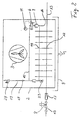
- Fig. 1 shows a part of a refrigeration system a schematically illustrated cooler 1 in the direction of the arrow a coolant, such as cold brine or the like, flows through is and is arranged in a housing 2 in which a blower 3 is provided, the air through the cooler or its cooling fins blows.
- a coolant such as cold brine or the like
- a the cooler bypass line 5 connected at 25 and 26, on which a heat exchanger 6 is arranged, through which Coolant in the bypass line 5 can be heated.
- a pump 7 is arranged in the Bypass line 5.
- a Shutoff valve 8 arranged in the coolant line 4 so that Cooler with the bypass line 5 compared to that not shown Coolant circuit can be shut off.
- a corresponding one Shut-off valve can also be located downstream of the cooler 1 and the Branch of the bypass line 5 can be arranged.
- At 9 is a drip pan with a drain 10 for the defrost water indicated.
- a water heater can also be used or another heating device can be provided by means of the the coolant flowing through the bypass line 5 are heated can.
- a temperature limiter is indicated, which Heat supply to the coolant to a certain temperature value limited.
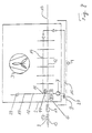
- Fig. 2 shows a modified embodiment in which the 1 from cooler 1 and bypass line 5 with Pump 7 and heater 6 as a heating register with a separate circuit 14, 15 arranged within a cooler 12 which is flowed through by a common coolant such as Frigen is that through the line 13 of the coolant circuit Refrigeration system flows.
- a common coolant such as Frigen
- Frigen that through the line 13 of the coolant circuit Refrigeration system flows.
- At 17 is an expansion valve in the Frigen refrigeration cycle shown. That from a heat transfer medium Heating register 14 through which flow forms a heat exchanger, by means of the heat is transferred to the cooler 12 to the inside defrost.
- the one in the separate and opposite the coolant circuit 12, 13 completed defrost cycle 15 circulating
- the heat transfer medium can be a warm brine.
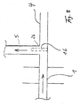
- Fig. 3 shows an immersion sleeve 16, according to the device Fig. 1 on the second branch 26 of the bypass line 5 from the Coolant line 4 for receiving a temperature probe is used to control the temperature of the circulating through the bypass To determine coolant.
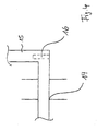
- Fig. 4 shows the corresponding Arrangement of an immersion sleeve 16 in the closed circuit 14, 15 of the heating register according to FIG. 2, the immersion sleeve 16 with Not shown temperature measuring probe in the return of the heat exchanger or the heating register arranged in front of the pump 7 is.
- the immersion sleeve 16 with the temperature measuring probe is in the return of the defrost heat exchanger so that the circulating in it Brine is measured at its coldest point after it was previously cooled by ice and thaw water. Because the warm brine in a separate circuit, the fin package of the cooler 12 flows through, is the coldest temperature in the return in front of the pump present within the defrost cycle.
- Fig. 2 shows schematically that through the separate circuit 14, 15 formed heat exchanger in the fin package of the cooler 12 is housed. Here run through the same Cooling fins package the line 13 of the refrigeration system and the line 14 of the defrost cycle.
- Slat package is a slat block in which two separate line systems are arranged.
- Fig. 2 also shows an expansion tube 19 with a sight glass 18 as level indicator. Through the expansion tube 18 can expand the brine when heated.
- Fig. 5 shows in detail the expansion tube 19 with a sight glass 18, with 21 the warm brine within that provided for defrosting Circuit 14, 15 is shown.
- At 20 is in 5 indicates an air cushion that can be compressed, when the brine expands by heating in the circuit 14, 15. 22 shows the level that is read in the sight glass 18 can be.
- the separate defrost circuit 14, 15 is at Room temperature through a filling valve 23 (Fig. 2) with brine to Center of the sight glass 18 filled.
- a Pressure relief valve shown at the end of the expansion tube 20, that opens, for example, at a pressure that is greater than 25 bar.
- This expansion tube 19 is inside the housing or attached directly to the housing so that the cooler with Defrosting device forms an assembly unit.
- FIG. 6 shows an air cooling evaporator 2 corresponding to FIG. 2 with a separate defrost circuit 14, 15, but in this embodiment 6 is guided through the condensate trough 9 and is used to thaw the ice there. At the same time, this arrangement prevents the freezing of prevents dripping condensation in the condensation tray 9.
- FIG. 6a shows a schematic top view of the course of the in the condensate pan 9 arranged line of the defrost circuit 14, 15, which improve the heat exchange in serpentine lines runs.
- Fig. 7 shows a modified embodiment of the arrangement Fig. 1, wherein the bypass line 5 also through the condensation pan 9 runs to thaw ice located there and thus the defrost water can drain freely at 10 and no further freezes.
- Fig. 8 shows an air cooling evaporator 2 with a separate defrost circuit 14, 15, in which the pump 7 in the defrost cycle hot brine located in countercurrent to the Frigen cooling circuit 13 promotes.
- the pump 7 of the completed defrost circuit 14, 15 can also continue to run during cooling operation in order to maintain a constant Reference temperature via the temperature probe or To determine immersion sleeve 16 so that, for example, the initiation defrost can be derived.
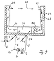
- Fig. 9 shows in a cross section a deep-freeze island as it is used for example in department stores for the presentation of frozen goods becomes.
- the outer insulation is U-shaped in cross section Designated housing 28 which to form a Cooling air circuit is hollow and in the upper area with Air outlet and inlet slots 29 is provided.
- a cooler 31 is arranged, through which a Blower 32 air is conveyed, the housing in the direction of the arrow 28 flows through and between the slots 29 a cooling air curtain 33 forms over the goods to be cooled.
- a cooling air curtain 33 forms over the goods to be cooled.
- a defrosting device according to FIG of such a deep-freeze island can be provided, the one shown in Fig. 2 at 14 and 15 shown defrost cycle so under the floor the cooling island is displaced, for example that the line section 15 with pump 7 and heat exchanger 6 directly outside the housing 28 attached to this while the line section 14 runs through the cooler 31, again releasable connection points between the line sections 14 and 15 accordingly the connection points 25 and 26 in Fig. 9 are provided so the defrost circuit is slightly removed from the outside for maintenance purposes and can be reassembled.
- Fig. 9 shows a thawing of the frozen goods in the housing 28 and thus preventing an interruption in the cold chain.
- coolers are provided in a refrigeration system, the Coolant supplied via common supply lines be, the defrosting device described on each individual cooler provided immediately, so that cooler and Defrosting device form a thermal unit, even if the defrost circuit is removably attached to the cooler, as with the embodiment of FIG. 9th
- the described embodiments give one rapid defrosting process, primarily heating up the goods is avoided in frozen food gondolas. Another advantage is that no water vapor forms during the defrosting process and saved up to 75% energy costs during the defrosting process can be. The heating connection values are low, so that current peaks are avoided.
- the Circulation of the warm brine during the defrosting process is clear Determination of the end of defrost temperature. A residual ice formation will not permitted by the described defrosting device on the air cooler, so that a constant cooling capacity in cooling mode is achieved. Finally, described by the Defrosting device relieves the environment in that less Primary energy is used.
- the expansion tube 19 can also be made from the cooling point (Fig. 2) are led out and with a expansion tank, not shown, may be connected.
- a expansion vessel not shown, may be connected.
- an expansion vessel be installed outside the cooling point 31.
- Fig. 9 can be between heater 6 and terminal 26
- Check valve can be provided in line 5 to a To prevent a short circuit between the defrost circuit and the cooling circuit.
Landscapes
- Engineering & Computer Science (AREA)
- Physics & Mathematics (AREA)
- Mechanical Engineering (AREA)
- Thermal Sciences (AREA)
- General Engineering & Computer Science (AREA)
- Chemical & Material Sciences (AREA)
- Combustion & Propulsion (AREA)
- Defrosting Systems (AREA)
Abstract
Description
- Fig. 1
- in einer schematischen Darstellung einen Kühler mit Abtauvorrichtung,
- Fig. 2
- schematisch eine Kühlanlage mit Abtauvorrichtung,
- Fig. 3
- die Anordnung einer Tauchhülse bei der Vorrichtung nach Fig. 1,
- Fig. 4
- die Anordnung einer Tauchhülse bei der Vorrichtung nach Fig. 2,
- Fig. 5
- die Anordnung einer Ausdehnungsleitung in der Vorrichtung nach Fig. 2,
- Fig. 6
- eine abgewandelte Ausführungsform der Vorrichtung nach Fig. 2,
- Fig. 7
- eine Abwandlung der Bauweise nach Fig. 1,
- Fig. 8
- eine weitere Abwandlung der Bauweise nach Fig. 2, und
- Fig. 9
- einen schematischen Querschnitt durch eine Tiefkühlinsel mit Abtauvorrichtung.
Claims (11)
- Verfahren zum Abtauen eines Kühlers bzw. Wärmetauschers in einer Kälteanlage, wobei der Kühler vom einem Kühlmittel wie kalter Sole durchströmt wird,
dadurch gekennzeichnet,
daß der Kühler (1) gegenüber dem Kühlmittelkreislauf abgesperrt und nur das im Kühler (1) befindliche Kühlmittel erwärmt wird, wobei man dieses durch den Kühler (1) über eine Bypassleitung (5) zirkulieren läßt. - Vorrichtung zum Abtauen eines Kühlers bzw. Wärmetauschers in einer Kälteanlage, bei der der Kühler von einem Kühlmittel wie Sole durchströmt wird,
dadurch gekennzeichnet,
daß eine den Kühler (1) umgehende Bypassleitung (5) vorgesehen ist, in der eine Pumpe (7) und eine Heizeinrichtung (6) angeordnet ist. - Vorrichtung nach Anspruch 2, wobei die Heizeinrichtung als Wärmetauscher ausgebildet ist.
- Vorrichtung nach Anspruch 2, wobei die Heizeinrichtung als Durchlauferhitzer ausgebildet ist.
- Vorrichtung nach einem der Ansprüche 2 bis 4, wobei ein Temperaturbegrenzer (11) an der Heizeinrichtung (6) vorgesehen ist.
- Vorrichtung zum Abtauen eines Kühlers in einer Kälteanlage, bei der der Kühler von einem Kühlmittel durchströmt wird,
dadurch gekennzeichnet,
daß in dem Kühler (12) ein Heizregister (14) in der Form eines Wärmetauschers angebracht ist, der in einem geschlossenen Kreislauf (15) mit einer Pumpe (7) und einer Heizeinrichtung (6) angeordnet ist. - Vorrichtung nach Anspruch 6, wobei den geschlossenen Kreislauf (15) des Heizregisters (14) Warmsole als Wärmeträger durchströmt.
- Vorrichtung nach einem der vorhergehenden Ansprüche, wobei in der Bypassleitung (5) bzw. in dem geschlossenen Kreislauf (15) eine Temperaturmeßsonde (16) im Rücklauf vor der Pumpe (7) angeordnet ist, mittels der die Temperatur des den Bypass bzw. den Kreislauf durchströmenden Kühlmittels bzw. der Warmsole zur Bestimmung des Abtauendes festgestellt werden kann.
- Vorrichtung nach Anspruch 8, wobei die Pumpe (7) während des Kühlbetriebs des Kühlers (12) in Betrieb bleibt und über die Temperatursonde (16) eine Referenztemperatur aus dem Kreislauf (15) zum Ermitteln einer Bedarfsabtauung abgenommen wird.
- Vorrichtung nach einem der vorhergehenden Ansprüche, wobei die Bypassleitung (5) bzw. ein Abschnitt des Abtaukreislaufs (14) durch die Tauwasserwanne (9) geführt ist.
- Vorrichtung nach einem der vorhergehenden Ansprüche, wobei die Bypassleitung (5) bzw. ein Abschnitt des Abtaukreislaufs (14) über lösbare Anschlußstellen (25, 26) mit der Kühlmittelleitung (4) bzw. dem verbleibenden Abschnitt des Abtaukreislaufs (15) lösbar verbunden ist.
Applications Claiming Priority (2)
| Application Number | Priority Date | Filing Date | Title |
|---|---|---|---|
| DE19644488A DE19644488A1 (de) | 1996-10-25 | 1996-10-25 | Verfahren und Vorrichtung zum Abtauen eines Kühlers einer Kälteanlage |
| DE19644488 | 1996-10-25 |
Publications (3)
| Publication Number | Publication Date |
|---|---|
| EP0838644A2 true EP0838644A2 (de) | 1998-04-29 |
| EP0838644A3 EP0838644A3 (de) | 2000-06-07 |
| EP0838644B1 EP0838644B1 (de) | 2004-06-16 |
Family
ID=7810037
Family Applications (1)
| Application Number | Title | Priority Date | Filing Date |
|---|---|---|---|
| EP97118534A Expired - Lifetime EP0838644B1 (de) | 1996-10-25 | 1997-10-24 | Verfahren und Vorrichtung zum Abtauen eines Kühlers einer Kälteanlage |
Country Status (2)
| Country | Link |
|---|---|
| EP (1) | EP0838644B1 (de) |
| DE (2) | DE19644488A1 (de) |
Cited By (2)
| Publication number | Priority date | Publication date | Assignee | Title |
|---|---|---|---|---|
| EP1347255A1 (de) * | 2002-03-20 | 2003-09-24 | Samsung Electronics Co. Ltd. | Abtauvorgang eines Wärmepumpenverdampfers |
| EP2664868A3 (de) * | 2012-05-15 | 2016-08-03 | Stiebel Eltron GmbH & Co. KG | Wärmepumpenvorrichtung und Verdampfer für eine Wärmepumpenvorrichtung |
Families Citing this family (3)
| Publication number | Priority date | Publication date | Assignee | Title |
|---|---|---|---|---|
| DE10307065B4 (de) * | 2003-02-19 | 2007-10-04 | Otto Junker Gmbh | Kühlkreislaufvorrichtung und Kühlverfahren |
| DE102015008325A1 (de) * | 2015-06-26 | 2016-12-29 | Voss Automotive Gmbh | Einrichtung und Verfahren zum Enteisen eines Wärmetauschers im Verdampferbetrieb einer Kälteanlage sowie Fahrzeug mit einer solchen Einrichtung |
| DE102022134719A1 (de) * | 2022-12-23 | 2024-07-04 | Eberspächer Catem Gmbh & Co. Kg | Wärmepumpsystem, Verwendung eines solchen Wärmepumpsystems zur Gebäudetrocknung und Verfahren zur Erwärmung von einem Fluid |
Family Cites Families (6)
| Publication number | Priority date | Publication date | Assignee | Title |
|---|---|---|---|---|
| US2693682A (en) * | 1952-06-25 | 1954-11-09 | Winger Milton | Refrigerating system with defrosting arrangement |
| US2954680A (en) * | 1957-03-28 | 1960-10-04 | V C Patterson & Associates Inc | Automatic defrosting apparatus |
| US3675441A (en) * | 1970-11-19 | 1972-07-11 | Clark Equipment Co | Two stage refrigeration plant having a plurality of first stage refrigeration systems |
| DE3012541A1 (de) * | 1980-03-31 | 1981-10-08 | Lahmeyer Ag, 6000 Frankfurt | Waermepumpenanlage, insbesondere fuer heizungszwecke |
| DE3243672A1 (de) * | 1982-11-25 | 1984-05-30 | KKW Kulmbacher Klimageräte-Werk GmbH, 8650 Kulmbach | Luft-wasser-waermepumpe |
| DE4321161C2 (de) * | 1993-06-25 | 2001-02-22 | Stiebel Eltron Gmbh & Co Kg | Wärmepumpenanlage |
-
1996
- 1996-10-25 DE DE19644488A patent/DE19644488A1/de not_active Ceased
-
1997
- 1997-10-24 EP EP97118534A patent/EP0838644B1/de not_active Expired - Lifetime
- 1997-10-24 DE DE59711716T patent/DE59711716D1/de not_active Expired - Lifetime
Non-Patent Citations (1)
| Title |
|---|
| None |
Cited By (3)
| Publication number | Priority date | Publication date | Assignee | Title |
|---|---|---|---|---|
| EP1347255A1 (de) * | 2002-03-20 | 2003-09-24 | Samsung Electronics Co. Ltd. | Abtauvorgang eines Wärmepumpenverdampfers |
| US7028499B2 (en) | 2002-03-20 | 2006-04-18 | Samsung Electronics Co., Ltd. | Refrigerator with an evaporator |
| EP2664868A3 (de) * | 2012-05-15 | 2016-08-03 | Stiebel Eltron GmbH & Co. KG | Wärmepumpenvorrichtung und Verdampfer für eine Wärmepumpenvorrichtung |
Also Published As
| Publication number | Publication date |
|---|---|
| DE19644488A1 (de) | 1998-04-30 |
| EP0838644B1 (de) | 2004-06-16 |
| DE59711716D1 (de) | 2004-07-22 |
| EP0838644A3 (de) | 2000-06-07 |
Similar Documents
| Publication | Publication Date | Title |
|---|---|---|
| DE69212356T2 (de) | Enteisungssteuerung | |
| DE69619050T2 (de) | Niedrigtemperatur-Schauvitrine | |
| DE69523573T2 (de) | Verfahren und vorrichtung für die kontinuierliche pasteurisierung von produkten | |
| DE1930050A1 (de) | Verfahren und Vorrichtung zum Enteisen von Verdampfern | |
| EP0274643B1 (de) | Klimaprüfkammer | |
| EP0838644B1 (de) | Verfahren und Vorrichtung zum Abtauen eines Kühlers einer Kälteanlage | |
| DE2711144A1 (de) | Verfahren zum betrieb einer waermepumpe | |
| DE60028837T2 (de) | Abtauverfahren für kühlschrank | |
| DE2623879C2 (de) | Kühlmöbel, insbesondere Zweitemperaturen-Kühlschrank | |
| DE29623827U1 (de) | Vorrichtung zum Abtauen eines Kühlers einer Kälteanlage | |
| DE2231769C3 (de) | Verfahren sowie Vorrichtung zum Eingefrieren und sicheren Gefrierlagern von Gütern | |
| DE4321161C2 (de) | Wärmepumpenanlage | |
| DE4410057C2 (de) | Kälteanlage mit einer Heißgasverteilung zur Heißgasabtauung der Verdampferrohre | |
| EP3093583B1 (de) | Verfahren und vorrichtung zum abtauen eines verdampfers einer kälteanlage sowie verwendung der abtauvorrichtung als kalorimeter | |
| DE3243672A1 (de) | Luft-wasser-waermepumpe | |
| EP0766051A1 (de) | Kälteanlage | |
| DE2554917A1 (de) | Waermepumpe | |
| EP0627602B1 (de) | Verfahren zum Betreiben einer Kälteanlage und Kälteanlage zum Betreiben dieses Verfahrens | |
| DE654493C (de) | Verfahren zum Abtauen von Trockenluftkuehlern | |
| DE1751732A1 (de) | Verfahren zum Abtauen eines Verdampfers und Kuehlmoebel zur Durchfuehrung des Verfahrens | |
| DE3022828C2 (de) | Verflüssiger einer Luft-Wasser-Wärmepumpe | |
| DE3808230A1 (de) | Verfahren und vorrichtung zum abtauen von eis an einem verdampfer eines kuehlaggregats | |
| DE29817062U1 (de) | Kühleinrichtung für Kühlvitrinen | |
| DE3023680A1 (de) | Waermepumpe | |
| AT3082U1 (de) | Kühleinrichtung für tiefkühlvitrinen |
Legal Events
| Date | Code | Title | Description |
|---|---|---|---|
| PUAI | Public reference made under article 153(3) epc to a published international application that has entered the european phase |
Free format text: ORIGINAL CODE: 0009012 |
|
| AK | Designated contracting states |
Kind code of ref document: A2 Designated state(s): BE CH DE GB LI LU NL SE |
|
| AX | Request for extension of the european patent |
Free format text: AL;LT;LV;RO;SI |
|
| PUAL | Search report despatched |
Free format text: ORIGINAL CODE: 0009013 |
|
| AK | Designated contracting states |
Kind code of ref document: A3 Designated state(s): AT BE CH DE DK ES FI FR GB GR IE IT LI LU MC NL PT SE |
|
| AX | Request for extension of the european patent |
Free format text: AL;LT;LV;RO;SI |
|
| 17P | Request for examination filed |
Effective date: 20001207 |
|
| AKX | Designation fees paid |
Free format text: BE CH DE GB LI LU NL SE |
|
| 17Q | First examination report despatched |
Effective date: 20021209 |
|
| GRAP | Despatch of communication of intention to grant a patent |
Free format text: ORIGINAL CODE: EPIDOSNIGR1 |
|
| GRAS | Grant fee paid |
Free format text: ORIGINAL CODE: EPIDOSNIGR3 |
|
| GRAA | (expected) grant |
Free format text: ORIGINAL CODE: 0009210 |
|
| AK | Designated contracting states |
Kind code of ref document: B1 Designated state(s): BE CH DE GB LI LU NL SE |
|
| REG | Reference to a national code |
Ref country code: GB Ref legal event code: FG4D Free format text: NOT ENGLISH |
|
| REG | Reference to a national code |
Ref country code: CH Ref legal event code: EP |
|
| REF | Corresponds to: |
Ref document number: 59711716 Country of ref document: DE Date of ref document: 20040722 Kind code of ref document: P |
|
| REG | Reference to a national code |
Ref country code: SE Ref legal event code: TRGR |
|
| GBT | Gb: translation of ep patent filed (gb section 77(6)(a)/1977) | ||
| PG25 | Lapsed in a contracting state [announced via postgrant information from national office to epo] |
Ref country code: LU Free format text: LAPSE BECAUSE OF NON-PAYMENT OF DUE FEES Effective date: 20041024 |
|
| PG25 | Lapsed in a contracting state [announced via postgrant information from national office to epo] |
Ref country code: LI Free format text: LAPSE BECAUSE OF NON-PAYMENT OF DUE FEES Effective date: 20041031 Ref country code: CH Free format text: LAPSE BECAUSE OF NON-PAYMENT OF DUE FEES Effective date: 20041031 Ref country code: BE Free format text: LAPSE BECAUSE OF NON-PAYMENT OF DUE FEES Effective date: 20041031 |
|
| PLBE | No opposition filed within time limit |
Free format text: ORIGINAL CODE: 0009261 |
|
| STAA | Information on the status of an ep patent application or granted ep patent |
Free format text: STATUS: NO OPPOSITION FILED WITHIN TIME LIMIT |
|
| BERE | Be: lapsed |
Owner name: MEYER, FRIEDHELM Effective date: 20041031 |
|
| 26N | No opposition filed |
Effective date: 20050317 |
|
| REG | Reference to a national code |
Ref country code: CH Ref legal event code: PL |
|
| PG25 | Lapsed in a contracting state [announced via postgrant information from national office to epo] |
Ref country code: SE Free format text: LAPSE BECAUSE OF NON-PAYMENT OF DUE FEES Effective date: 20051025 |
|
| PGFP | Annual fee paid to national office [announced via postgrant information from national office to epo] |
Ref country code: GB Payment date: 20060424 Year of fee payment: 9 |
|
| PGFP | Annual fee paid to national office [announced via postgrant information from national office to epo] |
Ref country code: SE Payment date: 20060427 Year of fee payment: 9 |
|
| PGFP | Annual fee paid to national office [announced via postgrant information from national office to epo] |
Ref country code: NL Payment date: 20060429 Year of fee payment: 9 |
|
| PG25 | Lapsed in a contracting state [announced via postgrant information from national office to epo] |
Ref country code: NL Free format text: LAPSE BECAUSE OF NON-PAYMENT OF DUE FEES Effective date: 20070501 |
|
| EUG | Se: european patent has lapsed | ||
| GBPC | Gb: european patent ceased through non-payment of renewal fee |
Effective date: 20061024 |
|
| NLV4 | Nl: lapsed or anulled due to non-payment of the annual fee |
Effective date: 20070501 |
|
| PG25 | Lapsed in a contracting state [announced via postgrant information from national office to epo] |
Ref country code: GB Free format text: LAPSE BECAUSE OF NON-PAYMENT OF DUE FEES Effective date: 20061024 |
|
| BERE | Be: lapsed |
Owner name: *MEYER FRIEDHELM Effective date: 20041031 |
|
| PGFP | Annual fee paid to national office [announced via postgrant information from national office to epo] |
Ref country code: DE Payment date: 20161028 Year of fee payment: 20 |
|
| REG | Reference to a national code |
Ref country code: DE Ref legal event code: R071 Ref document number: 59711716 Country of ref document: DE |