EP0838588A2 - Injecteur de combustible actionné hydrauliquement avec soupape de détente de pointes de pression - Google Patents
Injecteur de combustible actionné hydrauliquement avec soupape de détente de pointes de pression Download PDFInfo
- Publication number
- EP0838588A2 EP0838588A2 EP97306881A EP97306881A EP0838588A2 EP 0838588 A2 EP0838588 A2 EP 0838588A2 EP 97306881 A EP97306881 A EP 97306881A EP 97306881 A EP97306881 A EP 97306881A EP 0838588 A2 EP0838588 A2 EP 0838588A2
- Authority
- EP
- European Patent Office
- Prior art keywords
- actuation fluid
- pressure
- valve member
- relief
- passage
- Prior art date
- Legal status (The legal status is an assumption and is not a legal conclusion. Google has not performed a legal analysis and makes no representation as to the accuracy of the status listed.)
- Withdrawn
Links
Images


Classifications
-
- F—MECHANICAL ENGINEERING; LIGHTING; HEATING; WEAPONS; BLASTING
- F02—COMBUSTION ENGINES; HOT-GAS OR COMBUSTION-PRODUCT ENGINE PLANTS
- F02M—SUPPLYING COMBUSTION ENGINES IN GENERAL WITH COMBUSTIBLE MIXTURES OR CONSTITUENTS THEREOF
- F02M45/00—Fuel-injection apparatus characterised by having a cyclic delivery of specific time/pressure or time/quantity relationship
- F02M45/02—Fuel-injection apparatus characterised by having a cyclic delivery of specific time/pressure or time/quantity relationship with each cyclic delivery being separated into two or more parts
- F02M45/04—Fuel-injection apparatus characterised by having a cyclic delivery of specific time/pressure or time/quantity relationship with each cyclic delivery being separated into two or more parts with a small initial part, e.g. initial part for partial load and initial and main part for full load
- F02M45/06—Pumps peculiar thereto
-
- F—MECHANICAL ENGINEERING; LIGHTING; HEATING; WEAPONS; BLASTING
- F02—COMBUSTION ENGINES; HOT-GAS OR COMBUSTION-PRODUCT ENGINE PLANTS
- F02M—SUPPLYING COMBUSTION ENGINES IN GENERAL WITH COMBUSTIBLE MIXTURES OR CONSTITUENTS THEREOF
- F02M57/00—Fuel-injectors combined or associated with other devices
- F02M57/02—Injectors structurally combined with fuel-injection pumps
- F02M57/022—Injectors structurally combined with fuel-injection pumps characterised by the pump drive
- F02M57/025—Injectors structurally combined with fuel-injection pumps characterised by the pump drive hydraulic, e.g. with pressure amplification
-
- F—MECHANICAL ENGINEERING; LIGHTING; HEATING; WEAPONS; BLASTING
- F02—COMBUSTION ENGINES; HOT-GAS OR COMBUSTION-PRODUCT ENGINE PLANTS
- F02M—SUPPLYING COMBUSTION ENGINES IN GENERAL WITH COMBUSTIBLE MIXTURES OR CONSTITUENTS THEREOF
- F02M59/00—Pumps specially adapted for fuel-injection and not provided for in groups F02M39/00 -F02M57/00, e.g. rotary cylinder-block type of pumps
- F02M59/44—Details, components parts, or accessories not provided for in, or of interest apart from, the apparatus of groups F02M59/02 - F02M59/42; Pumps having transducers, e.g. to measure displacement of pump rack or piston
- F02M59/46—Valves
Definitions
- the present invention relates generally to fuel injection, and more particularly to hydraulically-actuated fuel injectors with means for avoiding and/or dissipating pressure spikes in the actuation fluid within the injector.
- the intensifier piston is acted upon by a relatively high pressure actuation fluid, such as engine lubricating oil, when a solenoid driven actuation fluid control valve opens the injector's high pressure inlet. Injection is ended by deactivating the solenoid to release pressure above the intensifier piston. This in turn causes a drop in fuel pressure causing the needle check to close under the action of its return spring to end injection. While these hydraulically actuated fuel injectors have performed beautifully over many years, there remains room for improvement, especially in the area of shaping an injection rate trace from beginning to end to precisely suit a set of engine operating conditions.
- a relatively high pressure actuation fluid such as engine lubricating oil
- One innovation that has been introduced recently to afford some ability to control the injection rate trace is by opening and closing the nozzle outlet by controlling the exposure of the end of the needle valve member to either low or high pressure, respectively.
- the end hydraulic surface of the needle valve member When the end hydraulic surface of the needle valve member is exposed to low pressure, it operates as a conventional needle check in that it opens when fuel pressure rises above a valve opening pressure sufficient to overcome a return spring.
- the end of the needle valve member is exposed to high pressure, it is held closed despite the presence of high fuel pressure acting upon the opposite lifting surfaces of the needle valve member.
- a direct control needle valve came a new problem which was rarely encountered in earlier hydraulically-actuated fuel injectors.
- the needle valve can close while the piston/plunger are in their downward stroke and fuel is above valve opening pressure, pressure spikes can be generated over some operating conditions of the injector. In some instances, these pressure spikes in the actuation fluid can cause a brief secondary injection.
- the present invention is intended to improve the ability of hydraulically-actuated fuel injectors to dissipate pressure spikes, or avoid pressure spike conditions, in the actuation fluid.
- a hydraulically-actuated fuel injector includes an injector body having a nozzle chamber, a nozzle outlet, an actuation fluid inlet, at least one actuation fluid drain, an actuation fluid cavity and a pressure relief passage extending between the actuation fluid cavity and the actuation fluid drain.
- a hydraulic means which includes an actuation fluid control valve mounted within the injector body, pressurizes fuel in the nozzle chamber.
- a needle valve member is mounted to reciprocate in the nozzle chamber between an open position in which the nozzle outlet is opened and a closed position in which the nozzle outlet is closed.
- a relief valve is mounted within the injector body and has a first position in which the pressure relief passage is closed and a second position in which the pressure relief passage is open.
- One object of the present invention is to dissipate pressure spikes in the actuation fluid of hydraulically-actuated fuel injectors.
- Another object of the present invention is to avoid pressure spike conditions in the actuation fluid of hydraulically-actuated fluid injectors with direct control needle valves.
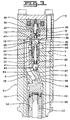
- fuel injector 2 utilizes a single two-way solenoid 30 to alternately open actuation fluid cavity 9 to actuation fluid inlet 6 or low pressure actuation fluid drain 4, and uses the same solenoid 30 to control the exposure of a needle control chamber 18 to a low pressure passage or a source of high pressure fluid.
- the single two-way solenoid of injector 2 accomplishes direct control of the needle valve by exploiting a hysteresis effect in the actuation fluid control valve versus the quick response of the needle valve member to the needle control valve.
- Injector 2 includes an injector body 5 having an actuation fluid inlet 6 that is connected to source of high pressure actuation fluid, such as lubricating oil, an actuation fluid drain 4 that is connected to a low pressure actuation fluid recirculation line, and a fuel inlet 20 connected to a source of fuel.
- Injector 2 includes a hydraulic means for pressurizing fuel within the injector during each injection event and a needle control valve that controls the opening and closing of nozzle outlet 17.
- the hydraulic means for pressurizing fuel includes an actuation fluid control valve that includes two-way solenoid 30 which is attached to a pin 35.
- An intensifier spool valve member 40 responds to movement of pin 35 and ball valve member 36 to alternately open actuation fluid cavity 9 to actuation fluid inlet 6 or low pressure drain 4.
- Actuation fluid cavity 9 opens to a stepped piston bore 10, 15 within which an intensifier piston 50 reciprocates between a return position (as shown) and a forward position. Actuation fluid cavity 9 can be thought of as including inner bore 15 and the upper part of bore 10 when piston 50 is in its forward position.
- Injector body 5 also includes a plunger bore 11, within which a plunger 53 reciprocates between a retracted position (as shown) and an advanced position.
- plunger bore 11 and plunger 53 define a fuel pressurization chamber 12, within which fuel is pressurized during each injection event.
- Plunger 53 and intensifier piston 50 are returned to their retracted positions between injection events under the action of compression spring 54.
- the hydraulic means for pressurizing fuel includes the fuel pressurization chamber 12, plunger 53, intensifier piston 50, actuation fluid inlet 6, actuation fluid cavity 9 and the various components of the actuation fluid control valve, which includes solenoid 30, ball 36, pin 35 and intensifier spool valve member 40, etc.
- a needle valve member 60 moves within nozzle chamber 14 between an open position in which nozzle outlet 17 is open and a closed position in which nozzle outlet 17 is closed.
- needle valve member 60 includes a lower needle portion 61 and an upper intensifier portion 62 separated by spacers 64 and 66, which are all machined as separate components, but could be machined as a single integral piece if spring 65 were relocated. Needle valve member 60 is mechanically biased to its closed position by compression spring 65.
- Needle valve member 60 includes opening hydraulic surfaces 63 exposed to fluid pressure within nozzle chamber 14 and a closing hydraulic surface 67 exposed to fluid pressure within needle control chamber 18.
- the closing hydraulic surface and the opening hydraulic surfaces are sized and arranged such that the needle valve member 60 is hydraulically biased toward its closed position when the needle control chamber 18 is open to a source of high pressure fluid.
- the opening hydraulic surfaces 63 and closing hydraulic surface 67 are also preferably sized and arranged such that needle valve member 60 is hydraulically biased toward its open position when the needle control chamber 18 is connected to a low pressure passage and the fuel pressure within nozzle chamber 14 is greater than the valve opening pressure necessary to overcome return spring 65.
- the actuation fluid control valve of injector 2 can be thought of as including two-way solenoid 30, which is attached to a pin 35 that is capable of contacting ball 36. Pin 35 is biased by a compression spring 38, and the hydraulic force on ball 36, toward a retracted position. In this position, ball 36 closes seat 72 and opens seat 73. This allows high pressure actuation fluid to flow into contact with the end hydraulic surface 41 of intensifier spool valve member 40 via a hidden connection passage 22 and a portion of actuation fluid control passage 19.
- solenoid 30 is de-energized, actuation fluid cavity 9 is opened to actuation fluid drain 4 past seat 70, and intensifier spool valve member 40 is hydraulically balanced and forced up, as shown, to close seat 71 and open seat 70.
- the opening and closing of the nozzle outlet 17 via needle valve member 60 is controlled by the needle control valve which also includes solenoid 30.
- the needle control valve which also includes solenoid 30.
- pin 35 retracts under the action of compression spring 38 so that high pressure actuation fluid flowing through hollow interior 47 pushes ball 36 to open seat 73 and close seat 72.
- the high pressure actuation fluid inlet 6 flows past seat 73 along a hidden passage into actuation fluid control passage 19.
- Actuation fluid control passage 19 opens to needle control chamber 18 and acts upon the closing hydraulic surface 67 of needle valve member 60, pushing the same downward to close nozzle outlet 17.
- solenoid 30 is energized, pin 35 is moved downward causing ball 36 to close seat 73 and open seat 72.
- the needle control valve includes solenoid 30, pin 35, ball 36, seat 72 and seat 73.
- the actuation fluid control valve includes all the components of the needle control valve plus intensifier spool valve member 40, compression spring 45, seat 70 and seat 71.
- a pressure spike can be created due to the abrupt stopping of the plunger and piston due to the abrupt closure of the nozzle outlet.
- This pressure spike in the actuation fluid cavity 9 temporarily raises the actuation fluid pressure above that in the common rail (not shown) connected to high pressure actuation fluid inlet 6.
- This pressure spike phenomenon can sometimes cause an undesirable and uncontrolled secondary injection, due to an interaction of components and passageways over a brief instant after main injection has ended.
- a pressure relief passage 81 extends between actuation fluid cavity 9 to a third low pressure drain 3, which merges with drains 4 and 8 outside of injector body 5.
- pressure relief passage 81 is preferably open to actuation fluid cavity 9 via an upper portion of piston bore 10 in the area above outer top surface 56.
- a portion of pressure relief passage 81 is machined into a seat 84 which receives relief ball 80.
- a relief pin 82 has one end in contact with relief ball 80 and another end having a hydraulic surface 85 exposed to the pressure of actuation fluid inlet 6, via hollow interior 47, radial openings 46 and high pressure actuation fluid inlet 6.
- Relief ball 80 includes a hydraulic surface 87 exposed to pressure in actuation fluid cavity 9 via pressure relief passage 81 and the upper portion of piston bore 10.
- Hydraulic surfaces 85 and 87 are sized and arranged such that relief pin 82 holds relief ball 80 in seat 84 when pressure in actuation fluid cavity 9 is below a threshold pressure, which is preferably lower than the common rail pressure leading to actuation fluid inlet 6.
- a threshold pressure which is preferably lower than the common rail pressure leading to actuation fluid inlet 6.
- end hydraulic surface 41 of spool valve member is again exposed to high pressure actuation fluid, preferably oil, past seat 73.
- high pressure actuation fluid preferably oil
- ball 80 lifts off of seat 84 and the combined forces of spring 45 and the pressure on ball 80 begin the spool valve member 40 moving upward.
- the force from ball 80 acting through pin 82 contacting on surface 44 of spool valve member 40 hastens its movement upward to open drain seat 70 and close high pressure seat 71.
- ball 80 provides a boost to hasten the movement of spool valve member 40, it also opens actuation fluid cavity 9 to a third low pressure drain 3 via pressure relief passageway 81 for a brief time period before seat 71 closes.
- the pressure relief valve which includes pin 82, ball 80 and seat 84, prevents the immediate over build-up of pressure following an injection event by allowing some high pressure actuation fluid to escape to drain, and also hastens the closure of high pressure seat 71.
- each injection sequence is started by energizing the solenoid 30 in order to move ball 36 to open seat 72 and close seat 73.
- the pressurized fluid previously acting on end hydraulic surface 41 of spool valve member 40 can now drain past seat 72.
- Intensifier spool valve member 40 is now hydraulically imbalanced and begins to move downward against the action of compression spring 45. This opens seat 71 and closes seat 70.
- the main oil supply can now flow through radial openings 46, past seat 71, into actuation fluid cavity 9 to the top of intensifier piston 50, starting it moving downward.
- solenoid 30 is initially energized with a maximum pull-in current so that ball 36 moves to open seat 72 and close seat 73. Shortly after the ball moves, the intensifier spool valve member begins to move from its closed position to its open position so that high pressure actuation fluid begins to flow into actuation fluid cavity 9, beginning the piston and plunger moving in their downward stroke. When fuel pressure within nozzle chamber exceeds the valve opening pressure sufficient to compress return spring 65, the needle valve member briefly opens to allow a pilot injection segment to occur.
- the solenoid is briefly de-energized a sufficient amount of time that the ball 36 moves back to its original position to open seat 73 and close seat 72. This again pressurizes the closing hydraulic surface of needle valve member 60 causing it to close (see Fig. 4e).
- intensifier spool valve member 40 becomes hydraulically balanced and begins to move to close seat 71 (see area A of Fig. 4c).
- spring 45 is relatively weak and pressure under relief ball 80 is insufficient to provide a boost, the intensifier spool valve member moves rather slowly.
- the solenoid is again energized causing ball 36 to again close seat 73 and re-open seat 72.
- solenoid 30 is de-energized. This causes ball 36 to open seat 73 and close seat 72. This resumes the pressurized actuation fluid acting on closing hydraulic surface 67 of needle valve member 60 to close and nozzle outlet 17 provide an abrupt end to the injection.
- the opening of seat 73 causes intensifier spool valve member 40 to again become hydraulically balanced so that compression spring 45, with help from the boost provided by the lifting of pressure relief ball 80 (see Fig. 4c) moves the same upward to close seat 71 and open seat 70. While this is occurring actuation fluid in actuation fluid cavity 9 drains initially through pressure relief passage 81 and eventually into actuation fluid drain 4 when seat 70 finally opens.
- Ball 80 returns to its seat when seat 70 opens drain 4. This permits intensifier piston 50 and plunger 53 to retract under the action of return spring 54. The lowering of fuel pressure within fuel pressurization chamber 12 causes ball check 21 to open. Replenishing fuel begins to flow into the injector for the next injection event.
- pressure relief passage 81 only exposed to the full pressure of actuation fluid cavity 9 after the main injection sequence has begun, pressure relief passage 81 only becomes important after piston 50 has moved to provide a direct pressure connection to the pressure of actuation fluid inlet 6.
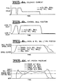
- Figs. 4a-g illustrate that the positions of the various components and the various injection parameters are substantially identical in the fuel injector shown in Figs. 1-3 with and without the relief valve of the present invention, except at the end portion of the injection event.
- Fig. 4g shows that without the pressure relief passage and valve, an undesirable secondary injection occurs after the main injection sequence. This occurs despite the fact that Figs. 4a-b illustrate that the current to the injectors are identical and the position of the control ball 36 is identical.
- Figs. 4c-f illustrate why the secondary injection occurs.
- Fig. 4c illustrate that without the relief valve, the spool moves from its open to its closed position much slower than the case where the relief valve is included. This is important since Fig. 4d shows that by leaving the high pressure inlet open, pressure surges in the actuation fluid cavity above the common rail pressure. This in turn causes a surge in fuel pressure as seen in Fig. 4f.
- needle valve member 60 The opening of needle valve member 60 is controlled by the differential pressures acting on its closing hydraulic surface 67 (actuation fluid) and opening hydraulic surfaces 63 (fuel).
- This differential pressure can be extracted from Figs. 4e and 4f to show that the pressure surge, which occurs when no relief valve is present, causes a brief and undesirable secondary injection to occur.
- the pressure spike conditions which could otherwise cause a secondary injection are vented via pressure relief passage 81 and avoided by the quicker closure of spool valve member 40.
- a spool or poppet valve could be substituted for the relief ball 80, relief pin 82 structure illustrated.
- the relief valve could be mechanically biased to its closed position rather than hydraulically biased as in the illustrated embodiment. In any event, what is important is that the injector have a way of dissipating pressure spikes or avoiding pressure spike conditions within the injector.
Landscapes
- Engineering & Computer Science (AREA)
- Chemical & Material Sciences (AREA)
- Combustion & Propulsion (AREA)
- Mechanical Engineering (AREA)
- General Engineering & Computer Science (AREA)
- Fuel-Injection Apparatus (AREA)
Applications Claiming Priority (2)
| Application Number | Priority Date | Filing Date | Title |
|---|---|---|---|
| US08/734,940 US5682858A (en) | 1996-10-22 | 1996-10-22 | Hydraulically-actuated fuel injector with pressure spike relief valve |
| US734940 | 1996-10-22 |
Publications (2)
| Publication Number | Publication Date |
|---|---|
| EP0838588A2 true EP0838588A2 (fr) | 1998-04-29 |
| EP0838588A3 EP0838588A3 (fr) | 1999-09-15 |
Family
ID=24953675
Family Applications (1)
| Application Number | Title | Priority Date | Filing Date |
|---|---|---|---|
| EP97306881A Withdrawn EP0838588A3 (fr) | 1996-10-22 | 1997-09-04 | Injecteur de combustible actionné hydrauliquement avec soupape de détente de pointes de pression |
Country Status (3)
| Country | Link |
|---|---|
| US (1) | US5682858A (fr) |
| EP (1) | EP0838588A3 (fr) |
| JP (1) | JPH10141174A (fr) |
Cited By (1)
| Publication number | Priority date | Publication date | Assignee | Title |
|---|---|---|---|---|
| GB2364103A (en) * | 2000-06-29 | 2002-01-16 | Bosch Gmbh Robert | High-pressure-resistant fuel injector with a spherical valve element |
Families Citing this family (62)
| Publication number | Priority date | Publication date | Assignee | Title |
|---|---|---|---|---|
| US6257499B1 (en) | 1994-06-06 | 2001-07-10 | Oded E. Sturman | High speed fuel injector |
| US6161770A (en) | 1994-06-06 | 2000-12-19 | Sturman; Oded E. | Hydraulically driven springless fuel injector |
| US6575137B2 (en) | 1994-07-29 | 2003-06-10 | Caterpillar Inc | Piston and barrel assembly with stepped top and hydraulically-actuated fuel injector utilizing same |
| DE19618698A1 (de) * | 1996-05-09 | 1997-11-13 | Bosch Gmbh Robert | Kraftstoffeinspritzventil für Brennkraftmaschinen |
| GB2351773B (en) * | 1997-02-26 | 2001-02-21 | Caterpillar Inc | Hydraulically actuated fuel injection system |
| US6026785A (en) * | 1998-05-08 | 2000-02-22 | Caterpillar Inc. | Hydraulically-actuated fuel injector with hydraulically assisted closure of needle valve |
| US6085991A (en) | 1998-05-14 | 2000-07-11 | Sturman; Oded E. | Intensified fuel injector having a lateral drain passage |
| US6085726A (en) * | 1998-05-20 | 2000-07-11 | Navistar International Transportation Corp. | Fuel injector |
| US6113000A (en) * | 1998-08-27 | 2000-09-05 | Caterpillar Inc. | Hydraulically-actuated fuel injector with intensifier piston always exposed to high pressure actuation fluid inlet |
| US6684853B1 (en) | 1998-10-16 | 2004-02-03 | International Engine Intellectual Property Company, Llc | Fuel injector with direct needle valve control |
| US6085992A (en) * | 1998-11-19 | 2000-07-11 | Caterpillar Inc. | Hydraulically-actuated fuel injector with rate shaping through restricted flow to intensifier piston |
| WO2000034646A1 (fr) * | 1998-12-11 | 2000-06-15 | Caterpillar Inc. | Ensemble piston et corps de pompe a partie superieure epaulee et injecteur de carburant actionne hydrauliquement utilisant ledit ensemble |
| EP1155233B1 (fr) | 1999-02-24 | 2005-01-19 | Siemens Aktiengesellschaft | Mecanisme de regulation permettant de commander une augmentation de pression de carburant, destine a un injecteur de carburant |
| DE19908217B4 (de) * | 1999-02-25 | 2005-03-17 | Siemens Ag | Anordnung und Verfahren zur Druckverstärkung von Kraftstoff für einen Kraftstoffinjektor |
| US6129072A (en) * | 1999-04-02 | 2000-10-10 | Caterpillar Inc. | Hydraulically actuated device having a ball valve member |
| US6286483B1 (en) | 1999-04-19 | 2001-09-11 | International Truck And Engine Corporation | Fuel injector with actuation pressure delay device |
| US6378497B1 (en) | 1999-11-18 | 2002-04-30 | Caterpillar Inc. | Actuation fluid adapter for hydraulically-actuated electronically-controlled fuel injector and engine using same |
| US6298826B1 (en) | 1999-12-17 | 2001-10-09 | Caterpillar Inc. | Control valve with internal flow path and fuel injector using same |
| JP2003522882A (ja) * | 2000-02-07 | 2003-07-29 | ローベルト ボツシユ ゲゼルシヤフト ミツト ベシユレンクテル ハフツング | 噴射ノズル |
| US6257203B1 (en) | 2000-02-10 | 2001-07-10 | International Truck And Engine Corporation | Injector with variable needle valve opening pressure |
| US6283441B1 (en) | 2000-02-10 | 2001-09-04 | Caterpillar Inc. | Pilot actuator and spool valve assembly |
| IT1319987B1 (it) * | 2000-03-21 | 2003-11-12 | Fiat Ricerche | Iniettore di combustione avente un'area di comando controllata dallapressione del combustibile in una camera di controllo. |
| US6499467B1 (en) * | 2000-03-31 | 2002-12-31 | Cummins Inc. | Closed nozzle fuel injector with improved controllabilty |
| US6354270B1 (en) | 2000-06-29 | 2002-03-12 | Caterpillar Inc. | Hydraulically actuated fuel injector including a pilot operated spool valve assembly and hydraulic system using same |
| US6749130B2 (en) * | 2000-12-08 | 2004-06-15 | Caterpillar Inc | Check line valve faster venting method |
| EP1383789A2 (fr) * | 2001-04-06 | 2004-01-28 | Incyte Genomics, Inc. | Proteines associees a la croissance , a la differnciation et a la mort cellulaire |
| US6655602B2 (en) | 2001-09-24 | 2003-12-02 | Caterpillar Inc | Fuel injector having a hydraulically actuated control valve and hydraulic system using same |
| US6845926B2 (en) * | 2002-02-05 | 2005-01-25 | International Engine Intellectual Property Company, Llc | Fuel injector with dual control valve |
| US6668530B2 (en) | 2002-03-13 | 2003-12-30 | Generac Power Systems, Inc. | Grass-cutting tractor with improved operating features |
| US6681743B2 (en) | 2002-04-02 | 2004-01-27 | International Engine Intellectual Property Company, Llc | Pressure control valve with flow recovery |
| US6712043B2 (en) | 2002-04-09 | 2004-03-30 | International Engine Intellectual Property Company, Llc | Actuating fluid control system |
| US6647964B1 (en) * | 2002-06-14 | 2003-11-18 | Caterpillar Inc | End of injection pressure reduction |
| US6845758B2 (en) | 2003-02-19 | 2005-01-25 | International Engine Intellectual Property Company, Llc | Fuel injector retainer assembly |
| US7059301B2 (en) | 2003-02-20 | 2006-06-13 | Caterpillar Inc. | End of injection rate shaping |
| US7219655B2 (en) * | 2003-02-28 | 2007-05-22 | Caterpillar Inc | Fuel injection system including two common rails for injecting fuel at two independently controlled pressures |
| US7528946B2 (en) * | 2003-03-31 | 2009-05-05 | The Charles Machine Works, Inc. | System for detecting deflection of a boring tool |
| US7108200B2 (en) * | 2003-05-30 | 2006-09-19 | Sturman Industries, Inc. | Fuel injectors and methods of fuel injection |
| US7182068B1 (en) | 2003-07-17 | 2007-02-27 | Sturman Industries, Inc. | Combustion cell adapted for an internal combustion engine |
| US20070107696A1 (en) * | 2004-02-25 | 2007-05-17 | Boris Feinleib | Two-stage distribution device of actuating fluid for hydraulically driven pump-injector for internal combustion engines |
| US7568633B2 (en) * | 2005-01-13 | 2009-08-04 | Sturman Digital Systems, Llc | Digital fuel injector, injection and hydraulic valve actuation module and engine and high pressure pump methods and apparatus |
| JP4305394B2 (ja) | 2005-01-25 | 2009-07-29 | 株式会社デンソー | 内燃機関用燃料噴射装置 |
| DE112006000387B4 (de) * | 2005-02-22 | 2014-08-21 | Continental Automotive Systems, Inc. ( n. d. Ges. d. Staates Delaware ) | Gemeinsames Druckleitungssystem mit Druckverstärkung |
| US20060192028A1 (en) * | 2005-02-28 | 2006-08-31 | Sturman Industries, Inc. | Hydraulically intensified injectors with passive valve and methods to help needle closing |
| US7412969B2 (en) | 2006-03-13 | 2008-08-19 | Sturman Industries, Inc. | Direct needle control fuel injectors and methods |
| US7793638B2 (en) | 2006-04-20 | 2010-09-14 | Sturman Digital Systems, Llc | Low emission high performance engines, multiple cylinder engines and operating methods |
| US7568632B2 (en) * | 2006-10-17 | 2009-08-04 | Sturman Digital Systems, Llc | Fuel injector with boosted needle closure |
| US20080264393A1 (en) * | 2007-04-30 | 2008-10-30 | Sturman Digital Systems, Llc | Methods of Operating Low Emission High Performance Compression Ignition Engines |
| CN102278248B (zh) | 2007-05-09 | 2013-08-28 | 斯德曼数字系统公司 | 具有主动针控制器的多级增强型喷射器的喷射方法 |
| US7954472B1 (en) | 2007-10-24 | 2011-06-07 | Sturman Digital Systems, Llc | High performance, low emission engines, multiple cylinder engines and operating methods |
| US7958864B2 (en) | 2008-01-18 | 2011-06-14 | Sturman Digital Systems, Llc | Compression ignition engines and methods |
| US7707993B2 (en) * | 2008-06-24 | 2010-05-04 | Caterpillar Inc. | Electronic pressure relief in a mechanically actuated fuel injector |
| US20100012745A1 (en) | 2008-07-15 | 2010-01-21 | Sturman Digital Systems, Llc | Fuel Injectors with Intensified Fuel Storage and Methods of Operating an Engine Therewith |
| US8596230B2 (en) | 2009-10-12 | 2013-12-03 | Sturman Digital Systems, Llc | Hydraulic internal combustion engines |
| US8887690B1 (en) | 2010-07-12 | 2014-11-18 | Sturman Digital Systems, Llc | Ammonia fueled mobile and stationary systems and methods |
| US20130186985A1 (en) * | 2010-09-13 | 2013-07-25 | International Engine Intellectual Property Company , Llc | Unit fuel injector having check valve body and spring cage forming a reverse flow check cavity |
| WO2012036660A1 (fr) * | 2010-09-13 | 2012-03-22 | International Engine Intellectual Property Company, Llc | Injecteur de carburant |
| US9206738B2 (en) | 2011-06-20 | 2015-12-08 | Sturman Digital Systems, Llc | Free piston engines with single hydraulic piston actuator and methods |
| US9464569B2 (en) | 2011-07-29 | 2016-10-11 | Sturman Digital Systems, Llc | Digital hydraulic opposed free piston engines and methods |
| US9181890B2 (en) | 2012-11-19 | 2015-11-10 | Sturman Digital Systems, Llc | Methods of operation of fuel injectors with intensified fuel storage |
| DE102013205624B4 (de) * | 2013-03-28 | 2015-07-09 | Continental Automotive Gmbh | Ventil zum Einblasen von gasförmigen Kraftstoffen für eine Brennstoffmaschine |
| US9903280B2 (en) | 2015-02-11 | 2018-02-27 | Husco Automotive Holdings Llc | Control valve with annular poppet check valve |
| US10544771B2 (en) * | 2017-06-14 | 2020-01-28 | Caterpillar Inc. | Fuel injector body with counterbore insert |
Citations (4)
| Publication number | Priority date | Publication date | Assignee | Title |
|---|---|---|---|---|
| US5121730A (en) | 1991-10-11 | 1992-06-16 | Caterpillar Inc. | Methods of conditioning fluid in an electronically-controlled unit injector for starting |
| US5271371A (en) | 1991-10-11 | 1993-12-21 | Caterpillar Inc. | Actuator and valve assembly for a hydraulically-actuated electronically-controlled injector |
| US5297523A (en) | 1993-02-26 | 1994-03-29 | Caterpillar Inc. | Tuned actuating fluid inlet manifold for a hydraulically-actuated fuel injection system |
| US5463996A (en) | 1994-07-29 | 1995-11-07 | Caterpillar Inc. | Hydraulically-actuated fluid injector having pre-injection pressurizable fluid storage chamber and direct-operated check |
Family Cites Families (13)
| Publication number | Priority date | Publication date | Assignee | Title |
|---|---|---|---|---|
| DE3341575C2 (de) * | 1983-11-17 | 1996-06-05 | Bosch Gmbh Robert | Druckventil für Kraftstoffeinspritzpumpen |
| DE3743532A1 (de) * | 1987-12-22 | 1989-07-06 | Bosch Gmbh Robert | Kraftstoffeinspritzanlage fuer brennkraftmaschinen |
| DE3813320A1 (de) * | 1988-04-08 | 1989-10-19 | Voest Alpine Automotive | Pumpenduese fuer dieselmotoren |
| US5035221A (en) * | 1989-01-11 | 1991-07-30 | Martin Tiby M | High pressure electronic common-rail fuel injection system for diesel engines |
| JP2963126B2 (ja) * | 1989-12-25 | 1999-10-12 | ヤマハ発動機株式会社 | エンジンの高圧燃料噴射装置 |
| BR9107316A (pt) * | 1991-10-11 | 1994-04-19 | Caterpillar Inc | Conjunto de atuador e valvula para um injetor controlado eletronicamente |
| US5143291A (en) * | 1992-03-16 | 1992-09-01 | Navistar International Transportation Corp. | Two-stage hydraulic electrically-controlled unit injector |
| US5492098A (en) * | 1993-03-01 | 1996-02-20 | Caterpillar Inc. | Flexible injection rate shaping device for a hydraulically-actuated fuel injection system |
| DE4332119B4 (de) * | 1993-09-22 | 2006-04-20 | Robert Bosch Gmbh | Kraftstoffeinspritzeinrichtung für Brennkraftmaschinen |
| DE4417950C1 (de) * | 1994-05-21 | 1995-05-11 | Mtu Friedrichshafen Gmbh | Einspritzsystem |
| US5826562A (en) * | 1994-07-29 | 1998-10-27 | Caterpillar Inc. | Piston and barrell assembly with stepped top and hydraulically-actuated fuel injector utilizing same |
| US5713520A (en) * | 1995-11-27 | 1998-02-03 | Caterpillar Inc. | Fast spill device for abruptly ending injection in a hydraulically actuated fuel injector |
| US5833146A (en) * | 1996-09-09 | 1998-11-10 | Caterpillar Inc. | Valve assembly with coupled seats and fuel injector using same |
-
1996
- 1996-10-22 US US08/734,940 patent/US5682858A/en not_active Expired - Fee Related
-
1997
- 1997-09-04 EP EP97306881A patent/EP0838588A3/fr not_active Withdrawn
- 1997-10-22 JP JP9289535A patent/JPH10141174A/ja not_active Withdrawn
Patent Citations (4)
| Publication number | Priority date | Publication date | Assignee | Title |
|---|---|---|---|---|
| US5121730A (en) | 1991-10-11 | 1992-06-16 | Caterpillar Inc. | Methods of conditioning fluid in an electronically-controlled unit injector for starting |
| US5271371A (en) | 1991-10-11 | 1993-12-21 | Caterpillar Inc. | Actuator and valve assembly for a hydraulically-actuated electronically-controlled injector |
| US5297523A (en) | 1993-02-26 | 1994-03-29 | Caterpillar Inc. | Tuned actuating fluid inlet manifold for a hydraulically-actuated fuel injection system |
| US5463996A (en) | 1994-07-29 | 1995-11-07 | Caterpillar Inc. | Hydraulically-actuated fluid injector having pre-injection pressurizable fluid storage chamber and direct-operated check |
Cited By (2)
| Publication number | Priority date | Publication date | Assignee | Title |
|---|---|---|---|---|
| GB2364103A (en) * | 2000-06-29 | 2002-01-16 | Bosch Gmbh Robert | High-pressure-resistant fuel injector with a spherical valve element |
| GB2364103B (en) * | 2000-06-29 | 2002-09-04 | Bosch Gmbh Robert | High pressure injector with a spherical control valve |
Also Published As
| Publication number | Publication date |
|---|---|
| JPH10141174A (ja) | 1998-05-26 |
| US5682858A (en) | 1997-11-04 |
| EP0838588A3 (fr) | 1999-09-15 |
Similar Documents
| Publication | Publication Date | Title |
|---|---|---|
| US5682858A (en) | Hydraulically-actuated fuel injector with pressure spike relief valve | |
| US6065450A (en) | Hydraulically-actuated fuel injector with direct control needle valve | |
| US5833146A (en) | Valve assembly with coupled seats and fuel injector using same | |
| EP1117927B1 (fr) | Injecteur de carburant a commande hydraulique dote d'un piston multiplicateur de pression toujours expose a l'admission de fluide d'actionnement a haute pression | |
| US5669355A (en) | Hydraulically-actuated fuel injector with direct control needle valve | |
| US6082332A (en) | Hydraulically-actuated fuel injector with direct control needle valve | |
| US5709341A (en) | Two-stage plunger for rate shaping in a fuel injector | |
| US5655501A (en) | Rate shaping plunger/piston assembly for a hydraulically actuated fuel injector | |
| EP1076768B1 (fr) | Injecteur de carburant a actionnement hydraulique avec fermeture hydraulique de la soupape a pointeau | |
| US6830202B2 (en) | Two stage intensifier | |
| US6655602B2 (en) | Fuel injector having a hydraulically actuated control valve and hydraulic system using same | |
| GB2334309A (en) | Fuel injector, for I.C. engines, having a intensifier piston with hydraulic stop means to provide abrupt end to injection event | |
| US6354270B1 (en) | Hydraulically actuated fuel injector including a pilot operated spool valve assembly and hydraulic system using same | |
| US6173699B1 (en) | Hydraulically-actuated fuel injector with electronically actuated spill valve | |
| EP0826877B1 (fr) | Injecteur de carburant à actionnement hydraulique avec une soupape à pointeau à commande directe | |
| US6412705B1 (en) | Hydraulically-actuated fuel injector having front end rate shaping capabilities and fuel injection system using same | |
| US6425375B1 (en) | Piston and barrel assembly with stepped top and hydraulically-actuated fuel injector utilizing same | |
| US6575137B2 (en) | Piston and barrel assembly with stepped top and hydraulically-actuated fuel injector utilizing same | |
| EP1152145B1 (fr) | Injecteur de carburant à actionnement hydraulique avec une soupape à pointeau à commande directe | |
| GB2332713A (en) | A pump assembly, for a fuel injector, having a seal which isolates part of a pressure surface on the pump piston |
Legal Events
| Date | Code | Title | Description |
|---|---|---|---|
| PUAI | Public reference made under article 153(3) epc to a published international application that has entered the european phase |
Free format text: ORIGINAL CODE: 0009012 |
|
| AK | Designated contracting states |
Kind code of ref document: A2 Designated state(s): DE FR GB |
|
| AX | Request for extension of the european patent |
Free format text: AL;LT;LV;RO;SI |
|
| PUAL | Search report despatched |
Free format text: ORIGINAL CODE: 0009013 |
|
| AK | Designated contracting states |
Kind code of ref document: A3 Designated state(s): AT BE CH DE DK ES FI FR GB GR IE IT LI LU MC NL PT SE |
|
| AX | Request for extension of the european patent |
Free format text: AL;LT;LV;RO;SI |
|
| RIC1 | Information provided on ipc code assigned before grant |
Free format text: 6F 02M 57/02 A, 6F 02M 47/02 B, 6F 02M 59/46 B, 6F 02M 45/04 B, 6F 02M 45/06 B |
|
| 17P | Request for examination filed |
Effective date: 20000221 |
|
| AKX | Designation fees paid |
Free format text: DE FR GB |
|
| 17Q | First examination report despatched |
Effective date: 20021106 |
|
| STAA | Information on the status of an ep patent application or granted ep patent |
Free format text: STATUS: THE APPLICATION IS DEEMED TO BE WITHDRAWN |
|
| 18D | Application deemed to be withdrawn |
Effective date: 20040629 |