EP0838176B1 - Dispositif de montage de parasols - Google Patents
Dispositif de montage de parasols Download PDFInfo
- Publication number
- EP0838176B1 EP0838176B1 EP97870165A EP97870165A EP0838176B1 EP 0838176 B1 EP0838176 B1 EP 0838176B1 EP 97870165 A EP97870165 A EP 97870165A EP 97870165 A EP97870165 A EP 97870165A EP 0838176 B1 EP0838176 B1 EP 0838176B1
- Authority
- EP
- European Patent Office
- Prior art keywords
- arm
- parasol
- hinge
- attached
- parts
- Prior art date
- Legal status (The legal status is an assumption and is not a legal conclusion. Google has not performed a legal analysis and makes no representation as to the accuracy of the status listed.)
- Expired - Lifetime
Links
Images


Classifications
-
- A—HUMAN NECESSITIES
- A45—HAND OR TRAVELLING ARTICLES
- A45B—WALKING STICKS; UMBRELLAS; LADIES' OR LIKE FANS
- A45B11/00—Umbrellas characterised by their shape or attachment
-
- E—FIXED CONSTRUCTIONS
- E04—BUILDING
- E04F—FINISHING WORK ON BUILDINGS, e.g. STAIRS, FLOORS
- E04F10/00—Sunshades, e.g. Florentine blinds or jalousies; Outside screens; Awnings or baldachins
- E04F10/02—Sunshades, e.g. Florentine blinds or jalousies; Outside screens; Awnings or baldachins of flexible canopy materials, e.g. canvas ; Baldachins
- E04F10/04—Sunshades, e.g. Florentine blinds or jalousies; Outside screens; Awnings or baldachins of flexible canopy materials, e.g. canvas ; Baldachins with material fixed on sections of a collapsible frame especially Florentine blinds
-
- F—MECHANICAL ENGINEERING; LIGHTING; HEATING; WEAPONS; BLASTING
- F16—ENGINEERING ELEMENTS AND UNITS; GENERAL MEASURES FOR PRODUCING AND MAINTAINING EFFECTIVE FUNCTIONING OF MACHINES OR INSTALLATIONS; THERMAL INSULATION IN GENERAL
- F16C—SHAFTS; FLEXIBLE SHAFTS; ELEMENTS OR CRANKSHAFT MECHANISMS; ROTARY BODIES OTHER THAN GEARING ELEMENTS; BEARINGS
- F16C11/00—Pivots; Pivotal connections
- F16C11/04—Pivotal connections
- F16C11/10—Arrangements for locking
- F16C11/103—Arrangements for locking frictionally clamped
-
- F—MECHANICAL ENGINEERING; LIGHTING; HEATING; WEAPONS; BLASTING
- F16—ENGINEERING ELEMENTS AND UNITS; GENERAL MEASURES FOR PRODUCING AND MAINTAINING EFFECTIVE FUNCTIONING OF MACHINES OR INSTALLATIONS; THERMAL INSULATION IN GENERAL
- F16M—FRAMES, CASINGS OR BEDS OF ENGINES, MACHINES OR APPARATUS, NOT SPECIFIC TO ENGINES, MACHINES OR APPARATUS PROVIDED FOR ELSEWHERE; STANDS; SUPPORTS
- F16M11/00—Stands or trestles as supports for apparatus or articles placed thereon Stands for scientific apparatus such as gravitational force meters
- F16M11/02—Heads
- F16M11/04—Means for attachment of apparatus; Means allowing adjustment of the apparatus relatively to the stand
- F16M11/06—Means for attachment of apparatus; Means allowing adjustment of the apparatus relatively to the stand allowing pivoting
- F16M11/10—Means for attachment of apparatus; Means allowing adjustment of the apparatus relatively to the stand allowing pivoting around a horizontal axis
-
- F—MECHANICAL ENGINEERING; LIGHTING; HEATING; WEAPONS; BLASTING
- F16—ENGINEERING ELEMENTS AND UNITS; GENERAL MEASURES FOR PRODUCING AND MAINTAINING EFFECTIVE FUNCTIONING OF MACHINES OR INSTALLATIONS; THERMAL INSULATION IN GENERAL
- F16M—FRAMES, CASINGS OR BEDS OF ENGINES, MACHINES OR APPARATUS, NOT SPECIFIC TO ENGINES, MACHINES OR APPARATUS PROVIDED FOR ELSEWHERE; STANDS; SUPPORTS
- F16M11/00—Stands or trestles as supports for apparatus or articles placed thereon Stands for scientific apparatus such as gravitational force meters
- F16M11/20—Undercarriages with or without wheels
- F16M11/2007—Undercarriages with or without wheels comprising means allowing pivoting adjustment
- F16M11/2014—Undercarriages with or without wheels comprising means allowing pivoting adjustment around a vertical axis
-
- F—MECHANICAL ENGINEERING; LIGHTING; HEATING; WEAPONS; BLASTING
- F16—ENGINEERING ELEMENTS AND UNITS; GENERAL MEASURES FOR PRODUCING AND MAINTAINING EFFECTIVE FUNCTIONING OF MACHINES OR INSTALLATIONS; THERMAL INSULATION IN GENERAL
- F16M—FRAMES, CASINGS OR BEDS OF ENGINES, MACHINES OR APPARATUS, NOT SPECIFIC TO ENGINES, MACHINES OR APPARATUS PROVIDED FOR ELSEWHERE; STANDS; SUPPORTS
- F16M11/00—Stands or trestles as supports for apparatus or articles placed thereon Stands for scientific apparatus such as gravitational force meters
- F16M11/20—Undercarriages with or without wheels
- F16M11/24—Undercarriages with or without wheels changeable in height or length of legs, also for transport only, e.g. by means of tubes screwed into each other
- F16M11/38—Undercarriages with or without wheels changeable in height or length of legs, also for transport only, e.g. by means of tubes screwed into each other by folding, e.g. pivoting or scissors tong mechanisms
-
- F—MECHANICAL ENGINEERING; LIGHTING; HEATING; WEAPONS; BLASTING
- F16—ENGINEERING ELEMENTS AND UNITS; GENERAL MEASURES FOR PRODUCING AND MAINTAINING EFFECTIVE FUNCTIONING OF MACHINES OR INSTALLATIONS; THERMAL INSULATION IN GENERAL
- F16M—FRAMES, CASINGS OR BEDS OF ENGINES, MACHINES OR APPARATUS, NOT SPECIFIC TO ENGINES, MACHINES OR APPARATUS PROVIDED FOR ELSEWHERE; STANDS; SUPPORTS
- F16M13/00—Other supports for positioning apparatus or articles; Means for steadying hand-held apparatus or articles
- F16M13/02—Other supports for positioning apparatus or articles; Means for steadying hand-held apparatus or articles for supporting on, or attaching to, an object, e.g. tree, gate, window-frame, cycle
-
- A—HUMAN NECESSITIES
- A45—HAND OR TRAVELLING ARTICLES
- A45B—WALKING STICKS; UMBRELLAS; LADIES' OR LIKE FANS
- A45B23/00—Other umbrellas
- A45B2023/0025—Umbrellas or sunshades mounted laterally on a wall or on an apparatus
-
- F—MECHANICAL ENGINEERING; LIGHTING; HEATING; WEAPONS; BLASTING
- F16—ENGINEERING ELEMENTS AND UNITS; GENERAL MEASURES FOR PRODUCING AND MAINTAINING EFFECTIVE FUNCTIONING OF MACHINES OR INSTALLATIONS; THERMAL INSULATION IN GENERAL
- F16M—FRAMES, CASINGS OR BEDS OF ENGINES, MACHINES OR APPARATUS, NOT SPECIFIC TO ENGINES, MACHINES OR APPARATUS PROVIDED FOR ELSEWHERE; STANDS; SUPPORTS
- F16M2200/00—Details of stands or supports
- F16M2200/02—Locking means
- F16M2200/021—Locking means for rotational movement
- F16M2200/022—Locking means for rotational movement by friction
-
- F—MECHANICAL ENGINEERING; LIGHTING; HEATING; WEAPONS; BLASTING
- F16—ENGINEERING ELEMENTS AND UNITS; GENERAL MEASURES FOR PRODUCING AND MAINTAINING EFFECTIVE FUNCTIONING OF MACHINES OR INSTALLATIONS; THERMAL INSULATION IN GENERAL
- F16M—FRAMES, CASINGS OR BEDS OF ENGINES, MACHINES OR APPARATUS, NOT SPECIFIC TO ENGINES, MACHINES OR APPARATUS PROVIDED FOR ELSEWHERE; STANDS; SUPPORTS
- F16M2200/00—Details of stands or supports
- F16M2200/06—Arms
- F16M2200/068—Arms being part of the undercarriage
Definitions
- the present invention relates to a device for mounting one or more parasols, avoiding congestion on the ground occurring during use classic parasols.
- tents or solar banners which are permanently fixed devices, for example on the facade of a building, usually above a balcony or a terrace, which allow to unwind or roll up a canvas as needed.
- Some of these tents solar panels have articulated arms arranged at both side edges of the tent, which support a sleeper on which is fixed one end of the tent, the other end winding on an axis housed in a box protection generally fixed to the wall.
- Umbrellas are also widely used. These, just like umbrellas, are made up of a handle and canvas stretched over a fixed folding frame articulated on the upper part of the handle and supported by a sliding ring on this handle. It is usual to provide an independent and relatively heavy to support this handle, and very often, umbrellas are mounted on tables such as tables terraces, provided with a central opening by which passes the handle. It is well known that umbrellas, depending on the course of the sun during the day and its height, do not generally assume imperfectly their sun protection function. For provide better protection, we have also provided parasols with the handle placed vertically on its base has a tilting upper part. In case bad weather, especially in strong winds, open umbrella tends to tip over, usually causing the table that supports it. When the sun disappears, it it is of course possible to fold the parasol, but it always remains bulky, since it occupies the center of the table. In case of storage, for example at the end feet are not only difficult to move, but are mostly bulky.
- a café terrace for example equipped each time with a parasol per table, is particularly crowded, without obtaining a adequate user protection while in front admit difficulties for service personnel.
- Document DE-3808327-A1 describes a support, formed by an articulated arm, which can be mounted by a jaw clamp on a table and intended in particular for a computer screen or the like.
- Each half-arm is ends at the end where the joint is provided by a internal sleeve and an external sleeve as well as by a trunnion mounted in rotation on the internal sleeve.
- the two ends of the half-arms provided with these elements are connected by connection plates.
- Such a device is not intended to withstand significant efforts, in particularly significant torsional forces.
- Document US-3297291-A describes an arm articulated support for optical devices such as magnifying glass, etc., which are attached to the end of a arm itself mounted for example on a table.
- This arm is also articulated and the articulation is constituted by two parallel axes connected by connection elements, allowing rotational movement, similar to connection plates described in the document previous and connected by a spacer.
- this device is designed to support weight elements restricted and is not intended to withstand the efforts of torsion.
- Document EP-0194021-A1 describes an arm articulated support for cameras for use film.
- the arm is made in the form of ladder-shaped elements, i.e. comprising two amounts connected by steps.
- the articulation between each of the ladder-shaped elements consists of cogwheels or parts of cogwheels meshing one inside the other, the arms being designed to be essentially "co-planar".
- These cogwheels are kept in the engaged position by seals or cover plates, themselves fixed by bolting. In this case too, the resistance to rotation is relatively low at the joint.
- GB-A-11555 describes a device to fix a parasol, comprising two arms, connected by a joint.
- the articulation allows rotation of arms, relative to each other, in planes horizontal parallel.
- One of the arms is attached to a adequate support.
- the other carries a parasol at its end.
- the joints are fixed using a gear system, which means that the attachment is very rigid and allows only a finite number of positions of one arm relative to the other.
- Document AU-58318/65-A describes a door articulated garage.
- the articulation which makes it possible to fold the different panels that constitute the door is formed by two axes provided with grooves which can mesh one in the other and also held at both ends by plates connected by bolting.
- This assembly is planned for a function essentially different from that contemplated by the present invention.
- the invention aims to provide a support improved for one or more parasols, which combines with less the advantages of tents or banners solar, namely their stability and their absence space, with the advantages of conventional parasols, that is, the fact that they are relatively inexpensive and that they are easy to orient and move and that can be stored easily, for example at the end of the summer season.
- a particular aim is the possibility of effectively protect multiple tables on one terrace, for example a café terrace, without major space requirement and keeping the appearance typical aesthetics of parasols, especially achieving an improved aesthetic appearance compared to classic arrangements of parasols.
- the different forms of execution of the invention is based on a basic concept, namely a articulated arm made up of at least two arm parts joined together by a hinge resistant to torsion, one end of the arm being fixed to a support fixed, preferably by an additional articulation and the other end of the arm possibly with interposition another additional joint being provided with a holding member for receiving the handle of a parasol, each joint being equipped with a device for quick release.
- the fixing device is equipped with an eccentric movement element ensuring blocking of the assembly.
- the arm is made up of two parts or in three main parts connected by joints. More than three main parts articulated for the arm are generally not necessary.
- the fixed arm support can be made either by a wall or by a mast fixed firmly to the ground, it being understood that a single fixed support can be equipped of one or in principle, unless limited in size, several parasol supports. A number of parasols ranging from 1 to 5 is generally suitable in the case of a mast of support.
- a lever device acting on a eccentric blocking has proven particularly useful in the context of the invention, not only to block the joints, but also to tighten the handle of the parasol on a fixation at the free end of the arm.
- the parasol can be of any size and shape.
- Figure 2 is a perspective view of this arms.
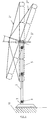
- the support bearing the general reference 1 is intended for a parasol which carries the general reference 2.
- this parasol in two different tilt positions (illustrated by 2 'and 2' ') in Figure 1, the ball joints or equipment similar to achieve this tilting of a parasol being classic.
- the arm 1 is constituted by a part 3 and part 5, these parts being connected by a articulation 7.
- An additional joint 8 is provided near the end which will be fixed to wall 10.
- the fixing to the wall is effected by a connecting element 9 which is kept on a wall by any suitable means, in particular by a device easy to disassemble.
- a holding piece 15 is designed so that the handle 17 of the parasol by jaws.
- this sleeve 17 is a shorter sleeve than that generally used for parasols mounted on tables which are usually fixed to their base by a fixing foot (you can of course use a classic parasol whose handle has been sawn to shorten it).
- the handle can be tilted relative to the vertical using a swivel or ball joint lockable 19 in the conventional manner.
- each of these joints is however provided with a blocking element, which is of the quick-release to eccentric locking element type.
- the fixing of the support is however not limited to fixing to a wall. On the contrary, and this constitutes a particularly form of execution interesting of the invention it and possible to fix several umbrellas, each time using an arm specific support for each parasol on a central pole.
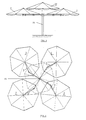
- FIGS 3 and 4 illustrate this way to operate.
- a central mast 21 fixed firmly to the ground, for example on a terrace, supports four articulated arms 3 each carrying end of a parasol 2.
- a umbrella 22 which must not be articulated and which, as well as shown in Figures 3 and 4, overcomes and covers partially the parasols 2.
- Figure 5 illustrates how using with a single articulated arm 3 fixed to a wall, it is possible, for example on the corner of a building, to move the parasol which it supports from a position, illustrated by position 2a passing through position 2b to reach finally position 2c depending on the position of the sun during the day.
- Figure 6 6 illustrates how the arm hinged can be folded against a wall
- Figure 7 the how the device shown in Figures 3 and 4 allows easy folding.
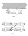
- the equipment comprises however a stirrup 31 which maintains complementary to the whole.
- the joint shown has two partially cylindrical and grooved elements 41 and 43 that can mesh with each other.
- the form cylindrical can only be partial as long as it allows sufficient pivoting movement.
- Each of the elements partially cylindrical fluted 41 and 43 has a bore 61 and 63 so that in assembled position, elements 41 and 43 mesh on each other, and that the rods 49 and 51 hold pads 45 and 47 in place suitable means, for example by bolting.
- a lever 65 makes it possible to actuate a system of blocking 65 by an eccentric pin disposed on the end of the rod 51.
Description
- La figure 1
- représente schématiquement la fixation d'un parasol par un bras articulé en deux parties principales, le bras étant fixé à une extrémité sur un mur.
- La figure 2
- représente une vue en perspective du bras articulé correspondant à celui de la figure 1.
- Les figures 3 et 4
- illustrent respectivement selon une vue de profil et une vue en élévation, une forme d'exécution particulière dans laquelle plusieurs parasols sont fixés sur un support unique sous forme d'un mât central.
- La figure 5
- illustre la possibilité de déplacer le parasol maintenu par un bras sur un mur en fonction de la position du soleil.
- La figure 6
- représente le bras articulé de la figure 2 en position repliée.
- La figure 7
- illustre la forme d'exécution particulière représentée aux figures 3 et 4 lorsque les bras articulés sont en position repliée.
- La figure 8
- représente une vue en perspective d'une articulation entre deux parties d'un bras.
- La figure 9
- représente une vue "éclatée" d'une articulation du même type que celui de la figure 8 montée à l'extrémité d'une partie de bras prévue pour être fixée sur un mur.
Claims (7)
- Dispositif de montage d'un ou plusieurs parasols (2), comprenant un bras articulé (1) constitué au moins par deux parties (3, 5) de bras, chaque pair de parties (3,5) de bras adjacentes étant solidarisées entre elles par une articulation (7) qui résiste à la torsion, une extrémité du bras étant fixée à un support fixe (10 ou 21) et l'autre extrémité du bras étant pourvue d'un organe de maintien (13, 15) pour recevoir le manche (17) d'un parasol (2), chaque articulation (7) étant équipée d'un dispositif de blocage rapide (65, 67),
caractérisé en ce que les articulations (7) sont réalisées sous forme de deux cylindres cannelés (41, 43) engrenant l'un par rapport à l'autre, ayant des cannelures sur toute leur longueur, fixés aux deux extrémités des parties (3,5) de bras et maintenus en position d'engrènement par deux plaquettes latérales perforées (45, 47), deux tiges (49, 51) étant pourvues pour assurer la solidarisation des extrémités de plaquettes respectives au cylindre cannelé correspondant, ledit dispositif de blocage rapide comprenant un axe excentrique disposé sur l'extrémité d'une des deux tiges (49, 51), ledit dispositif de blocage étant actionné par un levier (65). - Dispositif selon la revendication 1,
caractérisé en ce que l'extrémité du bras fixée au support fixe (10 ou 21) comporte une articulation (8) supplémentaire du même type que l'articulation entre deux parties (3,5) de bras et équipée du même dispositif de blocage rapide (65,67). - Dispositif selon la revendication 1 ou 2,
caractérisé en ce que l'extrémité du bras pourvue de l'organe de maintien (13, 15) comporte une articulation supplémentaire (11) du même type que l'articulation entre deux parties (3,5) de bras et équipée du même dispositif de blocage rapide (65,67). - Dispositif selon l'une quelconque des revendications précédentes, caractérisé en ce que le bras articulé est constitué en deux parties ou en trois parties principales reliées par des articulations (7).
- Dispositif selon l'une quelconque des revendications précédentes, caractérisé en ce que le support fixe du bras est constitué par un mur (10) ou par un mât (21) fixé solidement au sol.
- Dispositif selon l'une quelconque des revendications précédentes, caractérisé en ce qu'à un mât (21) sont fixés plusieurs bras articulés supportant chacun un parasol, ces parasols étant surmontés d'un parasol fixé directement au mât.
- Dispositif selon l'une quelconque des revendications précédentes, caractérisé en ce que l'organe de maintien (13, 15) du parasol (2) permet d'incliner celui-ci par rapport au bras articulé (1).
Applications Claiming Priority (2)
| Application Number | Priority Date | Filing Date | Title |
|---|---|---|---|
| BE9600913A BE1010718A3 (nl) | 1996-10-25 | 1996-10-25 | Scharnierbare arm, in het bijzonder voor het houden van een parasol, alsmede scharnier toepasbaar in een scharnierbare arm. |
| BE9600913 | 1996-10-25 |
Publications (2)
| Publication Number | Publication Date |
|---|---|
| EP0838176A1 EP0838176A1 (fr) | 1998-04-29 |
| EP0838176B1 true EP0838176B1 (fr) | 2003-03-19 |
Family
ID=3890065
Family Applications (1)
| Application Number | Title | Priority Date | Filing Date |
|---|---|---|---|
| EP97870165A Expired - Lifetime EP0838176B1 (fr) | 1996-10-25 | 1997-10-24 | Dispositif de montage de parasols |
Country Status (5)
| Country | Link |
|---|---|
| EP (1) | EP0838176B1 (fr) |
| AT (1) | ATE234576T1 (fr) |
| BE (1) | BE1010718A3 (fr) |
| DE (1) | DE69719904T2 (fr) |
| ES (1) | ES2195110T3 (fr) |
Cited By (2)
| Publication number | Priority date | Publication date | Assignee | Title |
|---|---|---|---|---|
| DE102007030364A1 (de) | 2007-06-29 | 2009-01-02 | Xaver Schneider Gmbh & Co. Kg | Klemmvorrichtung zum Befestigen einer Stange, insbesondere eines Schirmstocks |
| WO2022089964A1 (fr) * | 2020-10-28 | 2022-05-05 | Moeckl Markus | Système de protection solaire orientable de manière flexible |
Families Citing this family (9)
| Publication number | Priority date | Publication date | Assignee | Title |
|---|---|---|---|---|
| BE1014673A3 (nl) * | 2002-03-01 | 2004-03-02 | Brutsaert Trading Bv Met Beper | Arm voor een scherm, meer speciaal een parasol, regenscherm of dergelijke. |
| EP1400185A1 (fr) | 2002-09-23 | 2004-03-24 | Symo | Bras de parasol articulé |
| FR2856158B1 (fr) * | 2003-06-13 | 2005-08-19 | Lionel Giacomuzzi | Dispositif pour la prise de photographie |
| ITMI20070687A1 (it) * | 2007-04-03 | 2008-10-04 | Nemo S P A | Dispositivo di articolazione con giunto intermedio, particolarmente per corpi illuminanti. |
| DE202013008525U1 (de) | 2013-09-25 | 2013-10-11 | Peter Peters | Sonnenschirmhalter |
| DE102013015974B4 (de) | 2013-09-25 | 2017-02-09 | Peter Peters | Sonnenschirmhalter |
| TWD187648S (zh) * | 2017-04-10 | 2018-01-01 | 青輔實業股份有限公司 | Part of the screen support |
| IT201800009778A1 (it) * | 2018-10-25 | 2020-04-25 | Marco Rossi | Sistema di movimentazione di uno o più ombrelloni, ed ombrellone dotato di detto sistema di movimentazione |
| DE102022108630A1 (de) | 2022-04-08 | 2023-10-12 | Markus Möckl | Flexibel ausrichtbares Sonnenschutzsystem mit einem Solarenergiewandler |
Family Cites Families (7)
| Publication number | Priority date | Publication date | Assignee | Title |
|---|---|---|---|---|
| GB191211555A (en) * | 1912-05-15 | 1913-05-08 | Sarah Elizabeth Seaton | Improvements in or relating to Appliances for Attaching Umbrellas, Parasols or the like to Objects. |
| FR802857A (fr) * | 1935-11-27 | 1936-09-17 | Anciennes Maisons Bach & Porte | Perfectionnements apportés aux parasols |
| US3297291A (en) * | 1965-02-03 | 1967-01-10 | Ednalite Corp | Articulate support arm assembly for optical devices |
| AU5831865A (en) * | 1966-05-03 | 1967-11-09 | Brian Symons Cedric | An improved hinge construction |
| GB2171448A (en) * | 1985-02-01 | 1986-08-28 | Samuelson Group Plc | Articulated support frame |
| DE3808327C2 (de) * | 1987-03-21 | 1997-10-23 | Krause Robert Gmbh Co Kg | Schwenkarmvorrichtung |
| DE4105479A1 (de) * | 1991-02-21 | 1992-08-27 | Anton May | Wetterschirmanordnung unter verwendung eines faltschirmkoerpers |
-
1996
- 1996-10-25 BE BE9600913A patent/BE1010718A3/nl not_active IP Right Cessation
-
1997
- 1997-10-24 EP EP97870165A patent/EP0838176B1/fr not_active Expired - Lifetime
- 1997-10-24 ES ES97870165T patent/ES2195110T3/es not_active Expired - Lifetime
- 1997-10-24 DE DE69719904T patent/DE69719904T2/de not_active Expired - Lifetime
- 1997-10-24 AT AT97870165T patent/ATE234576T1/de not_active IP Right Cessation
Cited By (2)
| Publication number | Priority date | Publication date | Assignee | Title |
|---|---|---|---|---|
| DE102007030364A1 (de) | 2007-06-29 | 2009-01-02 | Xaver Schneider Gmbh & Co. Kg | Klemmvorrichtung zum Befestigen einer Stange, insbesondere eines Schirmstocks |
| WO2022089964A1 (fr) * | 2020-10-28 | 2022-05-05 | Moeckl Markus | Système de protection solaire orientable de manière flexible |
Also Published As
| Publication number | Publication date |
|---|---|
| EP0838176A1 (fr) | 1998-04-29 |
| ATE234576T1 (de) | 2003-04-15 |
| DE69719904T2 (de) | 2003-12-24 |
| DE69719904D1 (de) | 2003-04-24 |
| ES2195110T3 (es) | 2003-12-01 |
| BE1010718A3 (nl) | 1998-12-01 |
Similar Documents
| Publication | Publication Date | Title |
|---|---|---|
| EP0838176B1 (fr) | Dispositif de montage de parasols | |
| CA2610810C (fr) | Systeme d'echelle, notamment pour vehicules | |
| FR2712914A1 (fr) | Ensemble pare-soleil, notamment pour la plage. | |
| FR2800778A3 (fr) | Dispositif analogue a un parasol | |
| FR2599768A1 (fr) | Structure de couverture deplacable fermante et ouvrante | |
| WO2011157969A1 (fr) | Ombriere composee de poteaux assujettis a une structure equipee d'elements de protection contre des agents atmospheriques exterieurs | |
| EP3048923B1 (fr) | Dispositif de protection a mecanisme de symetrie | |
| FR2614920A1 (fr) | Armature formant support pour une toile de tente d'un abri leger | |
| FR2756551A1 (fr) | Procede et dispositif pour le montage des tirants des fleches de grues a tour | |
| EP0466661B1 (fr) | Parasol | |
| WO2002004336A1 (fr) | Grue avec fleche articulee | |
| EP1239748B1 (fr) | Armature pour objets deployables tels que parapluies | |
| EP0360702A1 (fr) | Grue repliable à flèche en deux ou trois éléments articulés les uns aux autres | |
| EP3030731B1 (fr) | Dispositif de structure de couverture exterieure d'un abri | |
| EP3011119B1 (fr) | Dispositif d'aménagement d'abri démontable et/ou pliable | |
| EP2291094B1 (fr) | Dispositif permettant de réduire la prise au vent de la toile de protection d'un parasol ou autre abri | |
| WO2012163917A2 (fr) | Dispositif de protection modulable | |
| EP1580351A1 (fr) | Dispositif de structure destiné à être assujetti à une structure formant abri | |
| EP0953301A1 (fr) | Parasol | |
| FR2613749A1 (fr) | Abri repliable | |
| WO2007051921A1 (fr) | Mat pour la fixation et la tension de toile permettant de s'abriter du soleil ou de la pluie | |
| FR2634242A1 (fr) | Abri a armature demontable en trois parties principales | |
| WO2021043427A1 (fr) | Boitier pour dispositif de protection contre les intempéries et/ou le soleil | |
| FR2934946A1 (fr) | Parasol-girouette | |
| FR2723299A1 (fr) | Dispositif de reglage de l'inclinaison d'un dossier pour siege a bascule du type balancelle |
Legal Events
| Date | Code | Title | Description |
|---|---|---|---|
| PUAI | Public reference made under article 153(3) epc to a published international application that has entered the european phase |
Free format text: ORIGINAL CODE: 0009012 |
|
| 17P | Request for examination filed |
Effective date: 19971104 |
|
| AK | Designated contracting states |
Kind code of ref document: A1 Designated state(s): AT BE CH DE DK ES FR GB GR IE IT LI NL PT SE |
|
| AX | Request for extension of the european patent |
Free format text: AL;LT;LV;RO;SI |
|
| AKX | Designation fees paid |
Free format text: AT BE CH DE DK ES FR GB GR IE IT LI NL PT SE |
|
| RBV | Designated contracting states (corrected) |
Designated state(s): AT BE CH DE DK ES FR GB GR IE IT LI NL PT SE |
|
| RAP3 | Party data changed (applicant data changed or rights of an application transferred) |
Owner name: LELEU, PETER |
|
| RIN1 | Information on inventor provided before grant (corrected) |
Inventor name: LELEU, PETER |
|
| 17Q | First examination report despatched |
Effective date: 20010111 |
|
| GRAG | Despatch of communication of intention to grant |
Free format text: ORIGINAL CODE: EPIDOS AGRA |
|
| GRAG | Despatch of communication of intention to grant |
Free format text: ORIGINAL CODE: EPIDOS AGRA |
|
| GRAH | Despatch of communication of intention to grant a patent |
Free format text: ORIGINAL CODE: EPIDOS IGRA |
|
| GRAH | Despatch of communication of intention to grant a patent |
Free format text: ORIGINAL CODE: EPIDOS IGRA |
|
| GRAA | (expected) grant |
Free format text: ORIGINAL CODE: 0009210 |
|
| AK | Designated contracting states |
Designated state(s): AT BE CH DE DK ES FR GB GR IE IT LI NL PT SE |
|
| PG25 | Lapsed in a contracting state [announced via postgrant information from national office to epo] |
Ref country code: IE Free format text: LAPSE BECAUSE OF FAILURE TO SUBMIT A TRANSLATION OF THE DESCRIPTION OR TO PAY THE FEE WITHIN THE PRESCRIBED TIME-LIMIT Effective date: 20030319 Ref country code: GR Free format text: LAPSE BECAUSE OF FAILURE TO SUBMIT A TRANSLATION OF THE DESCRIPTION OR TO PAY THE FEE WITHIN THE PRESCRIBED TIME-LIMIT Effective date: 20030319 |
|
| REG | Reference to a national code |
Ref country code: GB Ref legal event code: FG4D Free format text: NOT ENGLISH |
|
| REG | Reference to a national code |
Ref country code: CH Ref legal event code: EP |
|
| REG | Reference to a national code |
Ref country code: IE Ref legal event code: FG4D Free format text: FRENCH |
|
| REF | Corresponds to: |
Ref document number: 69719904 Country of ref document: DE Date of ref document: 20030424 Kind code of ref document: P |
|
| PG25 | Lapsed in a contracting state [announced via postgrant information from national office to epo] |
Ref country code: SE Free format text: LAPSE BECAUSE OF FAILURE TO SUBMIT A TRANSLATION OF THE DESCRIPTION OR TO PAY THE FEE WITHIN THE PRESCRIBED TIME-LIMIT Effective date: 20030619 Ref country code: DK Free format text: LAPSE BECAUSE OF FAILURE TO SUBMIT A TRANSLATION OF THE DESCRIPTION OR TO PAY THE FEE WITHIN THE PRESCRIBED TIME-LIMIT Effective date: 20030619 |
|
| PG25 | Lapsed in a contracting state [announced via postgrant information from national office to epo] |
Ref country code: PT Free format text: LAPSE BECAUSE OF FAILURE TO SUBMIT A TRANSLATION OF THE DESCRIPTION OR TO PAY THE FEE WITHIN THE PRESCRIBED TIME-LIMIT Effective date: 20030620 |
|
| REG | Reference to a national code |
Ref country code: CH Ref legal event code: NV Representative=s name: CRONIN INTELLECTUAL PROPERTY |
|
| GBT | Gb: translation of ep patent filed (gb section 77(6)(a)/1977) |
Effective date: 20030714 |
|
| REG | Reference to a national code |
Ref country code: IE Ref legal event code: FD4D Ref document number: 0838176E Country of ref document: IE |
|
| PLBE | No opposition filed within time limit |
Free format text: ORIGINAL CODE: 0009261 |
|
| STAA | Information on the status of an ep patent application or granted ep patent |
Free format text: STATUS: NO OPPOSITION FILED WITHIN TIME LIMIT |
|
| 26N | No opposition filed |
Effective date: 20031222 |
|
| REG | Reference to a national code |
Ref country code: CH Ref legal event code: PCAR Free format text: CRONIN INTELLECTUAL PROPERTY;CHEMIN DE PRECOSSY 31;1260 NYON (CH) |
|
| PGFP | Annual fee paid to national office [announced via postgrant information from national office to epo] |
Ref country code: CH Payment date: 20070925 Year of fee payment: 11 |
|
| PGFP | Annual fee paid to national office [announced via postgrant information from national office to epo] |
Ref country code: AT Payment date: 20070924 Year of fee payment: 11 |
|
| REG | Reference to a national code |
Ref country code: CH Ref legal event code: PL |
|
| PG25 | Lapsed in a contracting state [announced via postgrant information from national office to epo] |
Ref country code: AT Free format text: LAPSE BECAUSE OF NON-PAYMENT OF DUE FEES Effective date: 20081024 |
|
| PG25 | Lapsed in a contracting state [announced via postgrant information from national office to epo] |
Ref country code: LI Free format text: LAPSE BECAUSE OF NON-PAYMENT OF DUE FEES Effective date: 20081031 Ref country code: CH Free format text: LAPSE BECAUSE OF NON-PAYMENT OF DUE FEES Effective date: 20081031 |
|
| PGFP | Annual fee paid to national office [announced via postgrant information from national office to epo] |
Ref country code: GB Payment date: 20101229 Year of fee payment: 14 |
|
| PGFP | Annual fee paid to national office [announced via postgrant information from national office to epo] |
Ref country code: NL Payment date: 20111025 Year of fee payment: 15 |
|
| REG | Reference to a national code |
Ref country code: NL Ref legal event code: V1 Effective date: 20130501 |
|
| GBPC | Gb: european patent ceased through non-payment of renewal fee |
Effective date: 20121024 |
|
| PG25 | Lapsed in a contracting state [announced via postgrant information from national office to epo] |
Ref country code: GB Free format text: LAPSE BECAUSE OF NON-PAYMENT OF DUE FEES Effective date: 20121024 |
|
| PG25 | Lapsed in a contracting state [announced via postgrant information from national office to epo] |
Ref country code: NL Free format text: LAPSE BECAUSE OF NON-PAYMENT OF DUE FEES Effective date: 20130501 |
|
| PGFP | Annual fee paid to national office [announced via postgrant information from national office to epo] |
Ref country code: FR Payment date: 20141022 Year of fee payment: 18 Ref country code: DE Payment date: 20141022 Year of fee payment: 18 Ref country code: ES Payment date: 20141028 Year of fee payment: 18 |
|
| PGFP | Annual fee paid to national office [announced via postgrant information from national office to epo] |
Ref country code: IT Payment date: 20141030 Year of fee payment: 18 |
|
| PGFP | Annual fee paid to national office [announced via postgrant information from national office to epo] |
Ref country code: BE Payment date: 20141021 Year of fee payment: 18 |
|
| REG | Reference to a national code |
Ref country code: DE Ref legal event code: R119 Ref document number: 69719904 Country of ref document: DE |
|
| PG25 | Lapsed in a contracting state [announced via postgrant information from national office to epo] |
Ref country code: IT Free format text: LAPSE BECAUSE OF NON-PAYMENT OF DUE FEES Effective date: 20151024 Ref country code: DE Free format text: LAPSE BECAUSE OF NON-PAYMENT OF DUE FEES Effective date: 20160503 |
|
| REG | Reference to a national code |
Ref country code: FR Ref legal event code: ST Effective date: 20160630 |
|
| PG25 | Lapsed in a contracting state [announced via postgrant information from national office to epo] |
Ref country code: FR Free format text: LAPSE BECAUSE OF NON-PAYMENT OF DUE FEES Effective date: 20151102 |
|
| REG | Reference to a national code |
Ref country code: ES Ref legal event code: FD2A Effective date: 20161125 |
|
| PG25 | Lapsed in a contracting state [announced via postgrant information from national office to epo] |
Ref country code: ES Free format text: LAPSE BECAUSE OF NON-PAYMENT OF DUE FEES Effective date: 20151025 |
|
| PG25 | Lapsed in a contracting state [announced via postgrant information from national office to epo] |
Ref country code: BE Free format text: LAPSE BECAUSE OF NON-PAYMENT OF DUE FEES Effective date: 20151031 |